Abstract
This paper describes an extension of the perturbation Monte Carlo method to model light transport when the phase function is arbitrarily perturbed. Current perturbation Monte Carlo methods allow perturbation of both the scattering and absorption coefficients, however, the phase function can not be varied. The more complex method we develop and test here is not limited in this way. We derive a rigorous perturbation Monte Carlo extension that can be applied to a large family of important biomedical light transport problems and demonstrate its greater computational efficiency compared with using conventional Monte Carlo simulations to produce forward transport problem solutions. The gains of the perturbation method occur because only a single baseline Monte Carlo simulation is needed to obtain forward solutions to other closely related problems whose input is described by perturbing one or more parameters from the input of the baseline problem. The new perturbation Monte Carlo methods are tested using tissue light scattering parameters relevant to epithelia where many tumors originate. The tissue model has parameters for the number density and average size of three classes of scatterers; whole nuclei, organelles such as lysosomes and mitochondria, and small particles such as ribosomes or large protein complexes. When these parameters or the wavelength is varied the scattering coefficient and the phase function vary. Perturbation calculations give accurate results over variations of ∼15–25% of the scattering parameters.
OCIS codes: (170.0170) Medical optics and biotechnology; (170.3660) Light propagation in tissues; (170.6510) Spectroscopy, tissue diagnostics; (170.6935) Tissue characterization
1. Introduction
Recently, there has been interest in analyzing optical reflectance spectra to obtain information about tissue microstructure. Light which enters tissue can be elastically scattered, inelastically scattered (Raman or fluorescence) or absorbed. Some of the light will return to the tissue surface and properties of this light including its wavelength dependent intensity can be measured. In this paper we focus on spectral measurements of elastically scattered light without consideration of the coherence properties. These techniques frequently use fiber optic probes and a variety of probe configurations have been developed to provide information about different light scattering properties and/or the tissue absorption. By adjusting probe parameters such as source-detector separations, numerical apertures, angle of fiber orientation, and fiber diameter, the depth of tissue sampled can be varied [1–5] sometimes with a concominant variation in what scattering properties are sampled [6]. Accurate modeling of light transport relevant to these probes would enable better recovery of optical properties and/or recovery of parameters that describe microstructure.
Light transport in tissue is described by the radiative transport equation (RTE). There are solutions to this equation for special cases such as the diffusion approximation that can be used when the source and detector are well-enough separated. However, the source-detector separations in optical reflectance measurements to study tissue microstructure are frequently small enough to preclude the use of diffusion theory. When source-detector separations are 200 μm or less, the reflectance depends on the form of the phase function [6,7]. Solutions of the RTE can be obtained through Monte Carlo (MC) simulations. These MC simulations can provide RTE solutions for any set of boundary conditions, light source and detector configurations and arbitrary tissue properties including any phase function. However, obtaining accurate solutions to the RTE with Monte Carlo simulations typically uses much more computer time than, say, diffusion-based modeling. Because of this, conventional Monte Carlo simulations often serve as a “gold standard” to validate new biophotonic models, but researchers are often unwilling to use Monte Carlo methods in clinical settings due to the increased computational time. As a result, faster but less accurate computational models (e.g., based on diffusion theory) are often used instead of Monte Carlo simulations [8, 9].
Methods for increasing the computational efficiency of Monte Carlo calculations include perturbation Monte Carlo (pMC) methods, scaling or condensed MC methods [10], as well as a combination of pMC and scaling methods [11]. Condensed MC simulations have been developed for a two-layer tissue model [12] and potential applications include using the simulations to train a neural network [13] or create a database [12] for optical tissue parameter determination. Examples of applications of pMC include the inverse problem for two-layered media [14, 15], accurate and rapid tissue image reconstruction [16], optical tomography [17], and time-resolved functional imaging [18, 19].
The condensed MC methods scale the photon weight and collection distance from the source using original and altered values of the scattering and absorption coefficients [12]. Scaling results have been compared to independent simulations run with identical phase functions, but varying scattering and absorption properties. Errors in reflectance were about 2% when scattering coefficients were varied by about ±15% along with some changes in absorption [12]. However, when the form of the phase function or the anisotropy coefficient was altered in the independent simulations much larger errors were found for small source detector separation [12].
This paper focuses on the extension of perturbation Monte Carlo methods [14] to arbitrary variations of the phase function. In this initial work, scattering through all azimuthal angles is assumed to be equally likely in both the baseline and perturbed simulations. Only the probability of scattering through the polar angle, θ, is perturbed. In other words, the MC simulations are restricted to unpolarized scattering from spherical particles.
2. Theory and methods
2.1. Model of the scattering parameters of tissue
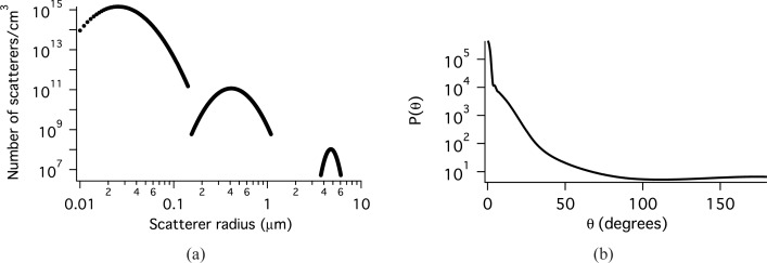
The sizes and indices of refraction of the tissue constituents that scatter light span a wide range [20–23]. Previously, we have shown that the distribution of scatter sizes can be modeled with three log normal distributions [24]. Each distribution models a different class of scatterers with different refractive indices. The parameters of these log-normal distributions, Eq. (1), have been modified slightly to obtain a value of the anisotropy coefficient, g closer to that reported in the literature for bronchial epithelium [25] and used in modeling cervical epithelium [26] and are given in Table 1. The smallest distribution models scattering from very small objects such as protein complexes. An index of 1.46 is appropriate for protein (or lipid) and an index of 1.33 is used for the medium. The second distribution models organelles such as lysosomes and mitochondria. The ratio of nscatterer to nmedium is smaller for these particles. The third distribution represents the nuclei. The size was obtained from microscopy and the index of refraction values are taken from the literature [27]. The values for number density demonstrate that there are many more organelles than there are nuclei in the cell and that there are orders of magnitude more of the smallest class of scatterers than there are organelles. The scatter distribution is plotted in Fig. 1(a) and the phase function at 620 nm in Fig. 1(b). For this model, the scattering coefficient μs = 126.3 cm−1, g = 0.954, and the reduced scattering coefficient μ′s = 5.84 cm−1 at 620 nm.
Table 1.
Distributions of scatter sizes in the tissue model
| Distribution | x̄ ± σ (μm) | N, number density (cm−3) | nmedium | nscatterer |
|---|---|---|---|---|
| 1 | 0.03 ± 0.4 | 4 × 10¹³ | 1.33 | 1.46 |
| 2 | 0.45 ± 0.3 | 5 × 10¹⁰ | 1.35 | 1.40 |
| 3 | 4.8 ± 0.1 | 5 × 10⁸ | 1.37 | 1.39 |
Fig. 1.
a) Scatterers per volume as a function of scatter radius. b) The phase function for the baseline MC simulation of epithelial tissue at 620 nm.
A scattering coefficient can be calculated for each distribution, k, according to Eqs. 1 and 2, where Lk(x) is the log normal distribution and Csca is the cross section calculated from Mie theory for a particle of radius x [28].
| (1) |
| (2) |
When there are multiple scatterers (or groups of scatterers) each with their own phase function then:
| (3) |
where fk is the phase function for the kth scattering type (or group), m is the number of scatterer types or groups and has a value of 3 for the model used here, and μs,k is the scattering coefficient of the kth group of scatterers [29]. The scattering coefficient is:
| (4) |
2.2. Measurement geometry
All of the simulations use the probe geometry shown in Fig. 2 at the surface of a semi-infinite medium. This source-detector configuration is composed of one source fiber and four detection fibers. Unpolarized light is launched into the tissue under investigation via the center fiber. The distance between the source fiber and the collection fiber is the same for all collection fibers. Therefore, to within statistical variation, the amount of light collected by each fiber is the same. The center-to-center distance between the source and any of the 4 detector fibers is 550 μm. The half angle for light delivery/collection is 21.7° for all source and collection fibers and the radius of the light cone at the sample surface is 240 μm for each fiber. The collection fibers are tilted at an angle of 20° from normal towards the collection fiber. This tilting increases sampling of the clinically relevant surface epithelium and also increases the number of collected photons.
Fig. 2.
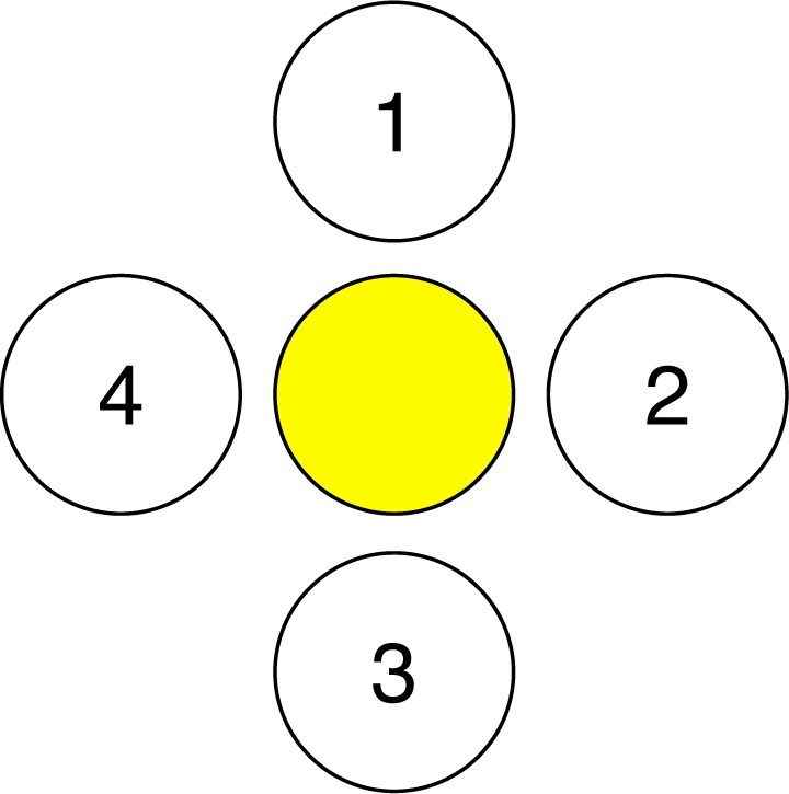
Source and detector setup for this study. The yellow fiber in the middle represents the photon source and 1, 2, 3, 4 represent detectors.
2.3. The connection between the RTE and Monte Carlo simulations
In biophotonics problems, the RTE is commonly used to describe interactions of light with tissue. Derivation of pMC equations requires an understanding of the equivalence between the equation-based analytic model that describes the physics and the probabilistic model that describes how to generate photon random walks and uses them to estimate the measurements desired.
We begin with the time-independent integro-differential form of the RTE:
| (5) |
where Φ is the photon radiance (#/area/sr), r is position, ω is a unit direction vector, μt is the optical interaction coefficient, μs is the optical scattering coefficient, f is the single-scattering phase function that scatters photons from ω′ to ω, and Q is the volumetric source.
It is useful to convert the integro-differential RTE to integral equation form when setting up for the Monte Carlo (probabilistic) mode. The integral equation for particle collision density is [30]:
| (6) |
where P = (r,ω) is a point in the phase space,. The kernel, K, describes both the positional and directional changes involved in scattering and transporting photons at r′ with direction ω′ to r with direction ω. In the case of no absorption, it is composed of the probability density for scattering from ω′ to ω, f (ω′ · ω), and the transport kernel T as shown in Eq. (7). The transport kernel, T, describes transport of photons in the direction ω from r′ to r [31] with l being the distance from r′ to r, as in Eq. (8). Ψ(P) is the collision density as shown in Eq. (9). Lastly, S(P) is the density of first collisions and Eq. (10) shows that the density of first collisions, S(P), is obtained by transporting each photon along its initial direction ω from the physical source Q to its collision location r.
| (7) |
| (8) |
| (9) |
| (10) |
Researchers are often interested in the reflectance or transmittance; this is expressed as the integral:
| (11) |
where d(P) is a “detector function” that describes the spatial locations and the unit direction vectors that characterize the physical detector, including its numerical aperture. Together, Eqs. 6 and 11 form the analytic model of the problem.
For our description of the probabilistic model we need to define the sample space ℬ whose elements describe all of the possible photon biographies [31]. Their likelihoods are described by a probability measure M on ℬ (so that M(ℬ) =1). The simplest choice for M is the analog measure MA that is induced when the starting location and direction of each biography is generated by sampling from a normalized version of the source function, S, and the transport kernel is used to move the photon to the first collision point, and additional collision points are generated by using the kernel K to change direction using f, and then move the photon to a new location using the transport kernel, T(r′ → r,ω). The final component of the probability model is an unbiased estimator ξ on ℬ that designates the contribution of every photon biography, Ci ∈ ℬ, to estimate the integral (11). The simplest example of such an unbiased estimator is the binomial estimator ξ whose value on the photon biographies is:
| (12) |
For these analog choices of the measure M and unbiased estimator, ξ, it is intuitively clear (and rigorously shown in [31]) that
| (13) |
The importance of Eq. (13) is that it establishes the equivalence of the analytic model, Eqs. (6), (11), and the probabilistic model (ℬ, M, ξ). The right side of Eq. (13) may also be written
| (14) |
where there are n possible photon biographies.
2.4. Perturbation Monte Carlo
The underlying idea of perturbation Monte Carlo, pMC, is to generate a single set of photon biographies according to the probability measure M and then define a new estimator that can be used to estimate collected light intensity using the same photon biographies for different (perturbed) conditions. For the perturbed conditions, Eq. (14) becomes Eq. (15) where hats denote perturbed conditions.
| (15) |
A new estimator, ξ̂(Ci) can be defined such that
| (16) |
then
| (17) |
The interpretation of (17) is that the expected value of ξ̂ with respect to the baseline measure M is identical to the expected value of the original variable ξ with respect to the modified measure M̂.
Here we want to draw attention to the benefits of using pMC to estimate detection in a physical system that has been perturbed - for example cancerous tissue or precancerous tissue. The conventional way to do this is to generate a new set of photon biographies in the perturbed system. The measure M̂ that is used to generate the biographies in the tumorogenic system is different from the measure M used to generate the biographies in the original system. For this work we assume all tissue systems are homogeneous, although that assumption can be easily relaxed [14]. If one is interested in estimating the reflection in a family of such perturbed tissue systems one would need to generate a different set of biographies for each member of the family, Mα. Calculating the photon trajectories for each precancerous and cancerous condition could be a prohibitively costly process. Instead, with pMC a single set of biographies is generated using the baseline measure M, and for each tumor condition the pMC estimator in Eq. (16) is used to estimate the collected intensity, Eq. (17).
The measure, M, is composed of the source term multiplied by a kernel term for every collision, i.e. S(P 0)T (P 0 → P 1)K(P 1 → P 2)K(P 2 → P 3)... When the source does not change, Eq. (18) holds for photons that enter a scattering medium, where j is the number of collisions undergone by the photon in the scattering medium. Kα and K are different for each scattering event, m, because they depend on the scattering angle.
| (18) |
This reweighting can be performed by a postprocessing algorithm that is quite inexpensive compared to the cost of generating different photon biographies for each set of tissue conditions. Explicit formulas will be given in the next section that make these ideas concrete.
2.5. Implementation of perturbation Monte Carlo
In our application of pMC, both the scattering coefficient and the phase function are perturbed. However, no absorption is used. Consequently, the corresponding K and K̂ are:
| (19) |
| (20) |
Using Eqs. (16) and (18) an estimator for the perturbed weight can be derived. In performing this derivation, the subtleties of the exit event must be considered. The exit or collection step of a photon transport Monte Carlo simulation is different than the others in that the photon does not go from one point to another point location, but rather must travel a distance at least as far as the distance to the collection surface. The probability of not reaching the detector is:
| (21) |
where Ls is the distance from the last (jth) collision inside the tissue to the point of photon exit out the tissue surface. Therefore, the probability of reaching the detector is e −μsLs. The estimator in Eq. (16) is then obtained using Eq. (18) and the expressions for T, Eq. (8), and K, Eq. (7). The entrance and collection events are separated out in the expression for the estimator in Eq. (22).
| (22) |
where j is the number of collisions inside the medium, lm is the length of step m in the medium. The phase functions, f and f̂ are functions of scattering angles θ and ϕ. Eq. (22) can be rewritten as
| (23) |
where L is the total distance traveled inside the scattering medium.
Before the perturbation Monte Carlo calculations are performed a baseline simulation is performed and several parameters are recorded for each collected photon. These are: the number of collisions; the total distance travelled by the photon; the number of the detector which collected the photon; and an array of θ values which is composed of the θ angle through which the photon scattered at every collision. To perform the perturbation calculation, Eq. (23) is evaluated for each photon using the tissue scattering parameters and the stored photon parameters.
A potential application of pMC is to understand the sensitivity of a particular optical measurement to tissue microarchitecture. If tissue is modeled as a distribution of scatterers, then parameters of interest are the mean radius, x̄k, of a scatter size distribution and the number density, Nk, of each scatter size distribution. For example, in the tissue model of this paper, the effects of an increase in the number of very small scatterers without any changes in the number or sizes of the nuclei and organelles could be determined by changing the number density of the smallest size distribution in Table 1.
Another feature of interest may be wavelength. For example, if multiple wavelengths are to be measured, then a pMC in which wavelength is varied could allow more rapid calculation of wavelength dependent simulation results for comparison of a tissue model and a measurement.
3. Testing of the pMC method
In this section, we examine the application of the phase function generalization of pMC to two problems that feature spherical scatterers with scattering properties representative of tissue, but with no absorption. In the first, simpler problem, concentration, radius, and incident light wavelength are varied for a suspension of single size scatterers. In the second problem, parameters of the tissue model in Table 1 and wavelength are altered.
In both cases pMC estimates of reflectance over a range of values of a given parameter are compared with conventional Monte Carlo (cMC) simulations. The cMC estimates are found by independent, conventional simulations, one for each value of the parameter in the range chosen, while pMC estimates are obtained from a single set of Monte Carlo biographies at the baseline value and estimates at other parameter values are determined using Eq. (23). We use the standard error of the mean to describe the stochastic variation of both cMC and pMC output values. A lack of overlap of the standard-error-of-the-mean error-bars does not imply that the means are different. However, these error bars should overlap most of the time.
To perform the most stringent test of the range of parameters over which pMC is accurate, the whole tissue will be perturbed rather than just a small tumorigenic region. The scattering medium is assumed to be semi-infinite with source and detector fibers on top, as described in Section 2.2.
For all simulations, the Bohren and Huffman [28] implementation of Mie theory, which uses the indices of refraction of the medium and the scatterers, the radius of the scatterers, and the wavelength of light as inputs, was used to generate tables for the phase functions, f(θ) and f̂(θ) for the full range of θ values. These tables of 720 elements are used for rapid sampling of the phase function both in the cMC simulations and the pMC calculations. The pMC calculation uses unperturbed as well as perturbed scattering parameters. These parameters as well as the saved trajectories are used according to Eq. (23) to reweight the photons. A separate set of trajectories is used for each collection fiber. Therefore, there are effectively four replicates of each pMC calculation.
The computers used for the simulations were: 1) 2 × 2.66 GHz Quad-Core Intel Xenon processors and 16 GB 1066MHz DDR3 RAM running Mac OS X 10.6.2; 2) 6 × 3.33 GHz Quad-Core Intel Xenon processors and 32 GB 1333 MHz DDR3 RAM running Mac OS X 10.8.2; and all code was compiled using gcc-4.2.
3.1. The simpler problem: one size of scatterers
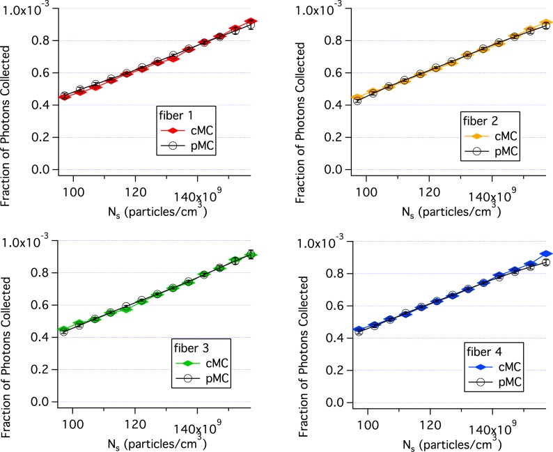
Figure 3 compares pMC and cMC results when the concentration of single size scatterers is perturbed. The parameter values for the baseline simulation were: the radius of the scatterers, r = 0.4475μm, the number density, Ns = 1.27 × 10¹² particles/cm3, the wavelength, λ = 620 nm, the index of the medium was 1.332, the index of the scatterers was 1.390 and 20 million photons were incident through the delivery fiber. Particle concentration was perturbed by ±25% for the pMC calculations. Each cMC simulation took 10 min. and the pMC calculations took ∼1 min using computer 2. Consequently, the pMC results were obtained in 11 min., much shorter than the 130 min. needed for the cMC calculations. The agreement between cMC and pMC results is quite good as seen in Fig. 3. By varying the concentration, the sensitivity of the perturbed reflectance to the weight factors described in Eq. (23) are determined without the phase function contribution.
Fig. 3.
Comparison of pMC estimates of reflectance with independent cMC simulations results when the concentration of single size scatterers is perturbed. Each panel is for a different collection fiber shown in Fig. 2. Error bars are standard errors of the mean.
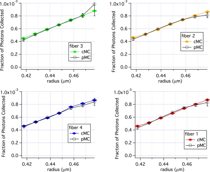
Varying the radius, r, will vary the phase function along with μs. Figure 4 shows the results of varying r using the same baseline simulation used for Fig. 3. There is good agreement from 0.4175 to 0.4775 μm, with some variation in the pMC results at r = 0.4775 μm.
| (24) |
Fig. 4.
Comparison of pMC estimates of reflectance with estimates of reflectance obtained from independent cMC simulations when the radius of a single size distribution is perturbed. Error bars are standard errors of the mean.
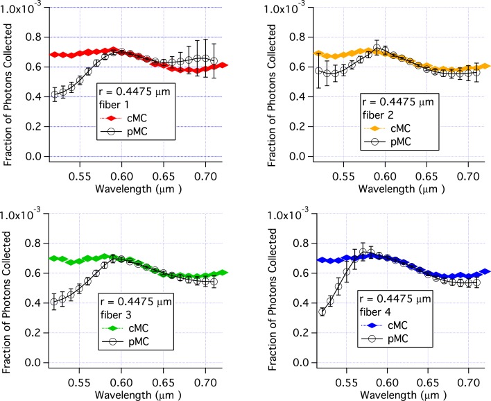
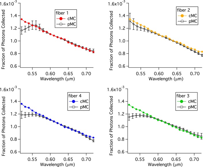
Similar to varying the radius, varying the wavelength changes both the phase function and μs, because the phase function and μs depend on the size parameter which is a function of wavelength as shown in Eq. (24). In Fig. (5), pMC and cMC results are compared for varying values of wavelength and constant values for other parameters. The parameters for the baseline simulation are the same as for Figs. 3 and 4. The agreement between pMC and cMC is excellent over the range 580 nm to 650 nm. However, for wavelengths of 550 nm and below, the pMC calculations underestimate the reflectance. Interestingly, large standard errors of the mean are not found in all cases, e.g. the results for fiber 4 at 520 nm. At wavelengths above 650 nm pMC results for one fiber over estimate reflectance while pMC results for the other three collection fibers under estimate the reflectance. Nonetheless, in most cases the standard error of the mean overlaps with the cMC result. The cMC results are nearly identical for each fiber. (When plotted on the same graph, the symbols overlap.) The pMC results, however, show a different trend for each fiber in Fig. 5 as a function of wavelength. The different trends for each fiber are due to the fact the pMC calculations for each fiber use a different base set of trajectories.
Fig. 5.
Comparison of pMC estimates of reflectance with independent cMC simulations results when wavelength is perturbed. The scattering particles had a radius of 447.5 nm. Each panel is for a different collection fiber shown in Fig. 2. Error bars are standard errors of the mean.
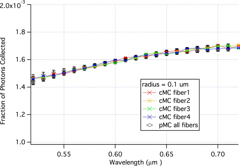
To investigate further the effects of the phase function on the accuracy of pMC, simulations varying wavelength were run with scatterers of 100 nm in radius. Excellent agreement between cMC and pMC was obtained as shown in Fig. 6. The baseline simulation used r = 0.100μm, Ns = 1.83 × 10¹⁰ particles/cm3, λ = 620 nm, nmedium = 1.332 and nscatterer = 1.390. Twenty million photons were incident for the baseline and cMC simulations.
Fig. 6.
Comparison of pMC estimates of reflectance with independent cMC simulations results when wavelength is perturbed. The scattering particles had a radius of 100 nm.
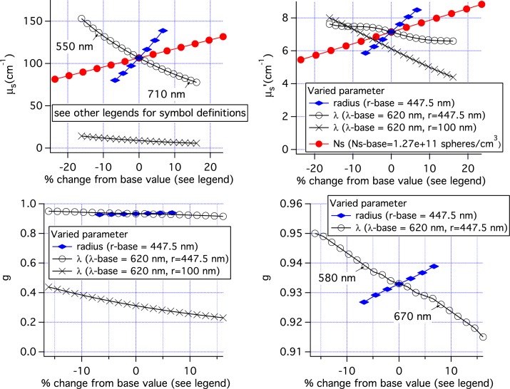
The results of Figs. 3, 4, 5, and 6 can be placed in a broader context by examination of the scattering parameters used in the simulations. Figure 7 shows these scattering parameters plotted versus the percent change in the varied parameter. When three sets of pMC simulations use the same baseline simulation such as the simulations varying Ns, radius, and λ of the 447.5 nm radius spheres, the parameters all overlap at the 0% point as in the top left graph for μs.
Fig. 7.
Scattering parameters used in the MC simulations incorporating only one scatterer size. Top left: μs. Top right: μ‘s. Bottom left: anisotropy coefficient g, Bottom right: g on an expanded scale.
The reflectance results when Ns and radius were varied are quite similar as shown in Figs. 3, and 4. This similarity is because the scattering parameters for the two sets of simulations were nearly the same. The range of μs values, shown in the top left panel of Fig. 7 is nearly the same. The anisotropy factor, g, was 0.933 for the set of simulations in which Ns was varied. For the set of simulations for which the radius was varied, g ranged from 0.927 to 0.939. Given these similarities in scattering parameters it is not surprising that the results in Figs. 3 and 4 are similar.
When λ is varied with r = 447.5 nm, the range of scattering coefficients, 78–153 cm−1, is slightly larger than when radius is varied, 80–139 cm−1. The variation in μs is nearly the same for the two sets of simulations when the wavelength range is restricted to 550–710 nm for simulations varying wavelength. However, Fig. 5 shows that pMC and cMC results are not the same over this range. Examination of the bottom right panel shows that g is varying more when wavelength is varied than when radius is varied even when only the range 550 to 710 nm is considered. Not until the wavelength range is reduced to 580 to 670 nm is the variation in g the same. This corresponds to the same range of wavelengths over which good agreement is found between the cMC and pMC results in Fig. 5. Clearly, the variation in g reduces the accuracy of the pMC results when g is large. However, if g is smaller, a much bigger variation in g can be tolerated as can be seen for the results using 100nm radius spheres in Fig. 6 and the bottom left panel of Fig. 7. Lastly, we note that variations in μ′s are not a good predictor of the accuracy of pMC for this geometry where delivery and collection fibers are close together. The top right panel shows that varying lambda resulted in the smallest variation in μ′s, while varying the concentration resulted in the largest variation of μ′s.
3.2. A more complex problem: three lognormal distributions of radii
The tissue model described in Section 2.1 is used for these simulations, with the parameters for the baseline simulation given in Table 1. As was done with the single size scatterers, concentration, radii, and wavelength are varied. However, rather than varying the concentration and mean radius of the entire suspension, the concentrations and mean radii of each distribution in Table 1 are varied. Consequently all perturbations in parameters modified the phase function.
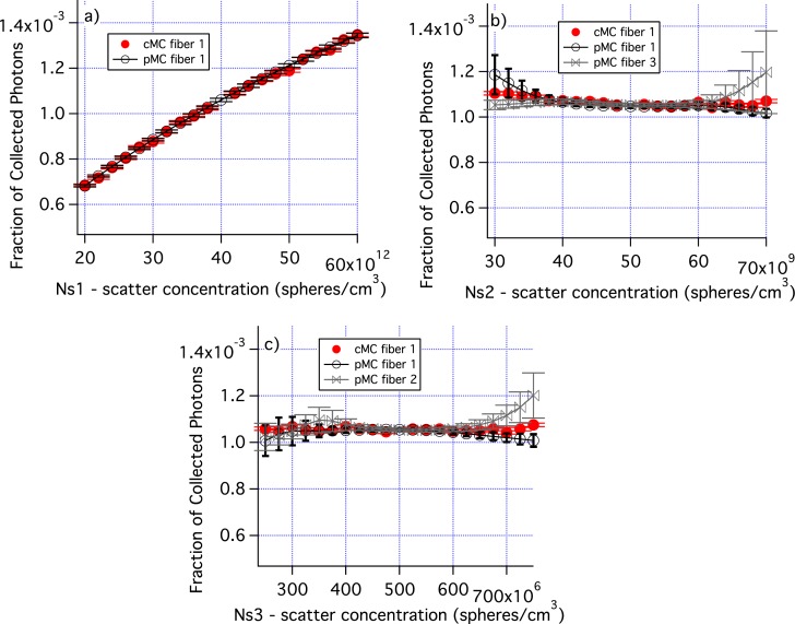
Figure 8 shows how varying the number density of each distribution affects the fraction of collected photons as well as the accuracy of the pMC results. Figure 8(a) demonstrates that when the concentration of the smallest distribution is varied by ± 50%, there is a large change in photon collection efficiency and the pMC results are very accurate. When the concentrations of distributions 2 and 3 are varied, there is very little change in photon collection efficiency. For larger changes in concentration, the standard errors of the mean increase for pMC. pMC results are shown for two fibers which are representative of the range of results obtained.
Fig. 8.
The number density of each of the distributions in Table 1 is varied. a) Ns for the smallest size distribution is varied. b) Ns for the middle size distribution is varied. c) Ns for the large size distribution is varied. Errors are standard error of the mean. Only cMC results for fiber 1 are shown for clarity. Similarly, only pMC results for one or two fibers are shown.
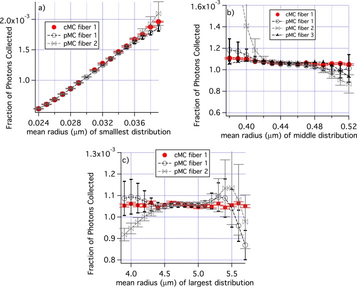
In Fig. 9, the mean radii of each individual distribution was varied. Figure 9(a) shows results for the variation of the smallest radius from a baseline value of 0.030 μm. The pMC and cMC results overlap for all radii and results are quite accurate at the smallest radius used, r = 0.024 μm. Figure 9(b) are results when the mean radius of the middle size distribution is varied from the baseline value of 0.045 μm. The pMC and cMC results agree well from about 0.42 μm to 0.49 μm, but the pMC results differ greatly from the cMC results for smaller radii in one case. Similar results were obtained when the radius of the largest distribution was varied, Fig. 9(c).
Fig. 9.
The mean radii of individual groups of scatterers are perturbed; a) distribution 1, b) distribution 2, and c) distribution 3 in Table 1. Only cMC results for fiber 1 are shown for clarity. Similarly, pMC results are shown for only some fibers. The range of the ”Fraction of Photons Collected” is different in panel a) from all other graphs of ”Fraction of Photons Collected”. The error bars are standard errors of the mean.
Figure 10 compares pMC and cMC results when the wavelength is perturbed from a baseline value of 620 nm. From 580 to 720 nm all of the pMC and cMC results are the same within errors. And for 3 of the 4 replicates, the agreement extends down to 560 nm.
Fig. 10.
Comparison of pMC estimates of reflectance across wavelengths with calculations of reflectance obtained from independent cMC simulations of tissue.
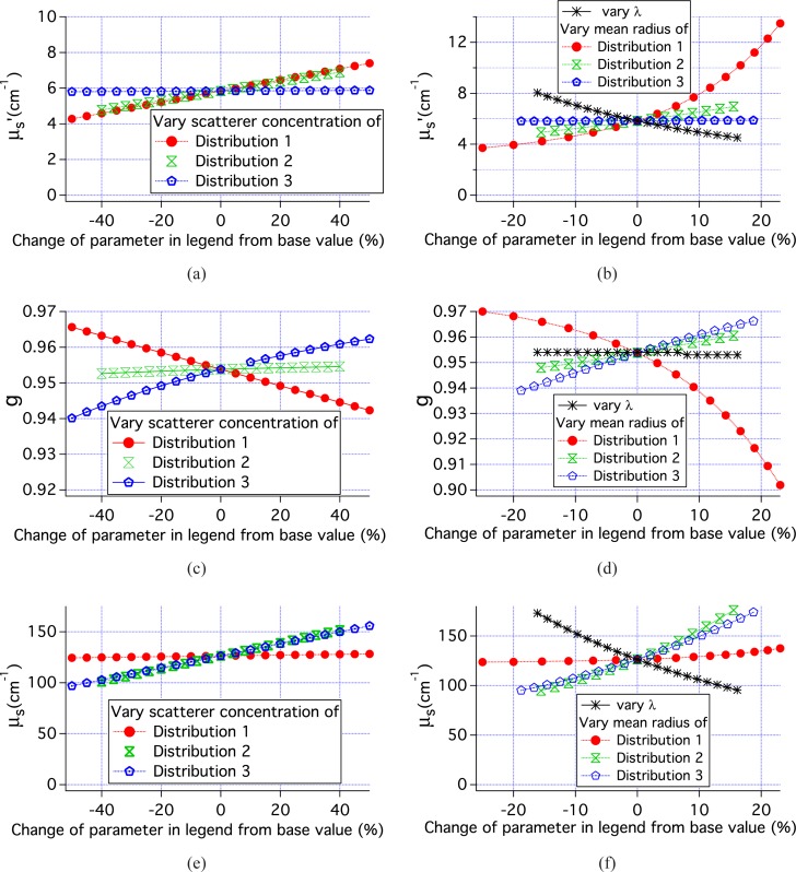
Figure 11 shows the parameters used in the MC simulations of tissue. Combining these data with those in Fig. 7 for single size scatterers with r = 447.5 nm, 4 classes of simulations can be examined; 1) μs varies, while g is constant or nearly constant, 2) g varies while μs is nearly constant, 3) both g and μs vary for nearly constant μ′s, and 4) g, μs and μ′s all vary. For each of these classes, there are 2 or 3 relevant simulations. By examining the pMC results for these simulations we can determine the range of scattering parameters over which the pMC and cMC results agree to within 1% of the cMC results. The results of this analysis are shown in Table 2. When only μs varied, pMC results are accurate over a range of ±15% the original value of μs. When only g varied, pMC results are accurate over a range of ±25% the original value of (1 − g). When both g and μs varied, then the variation of μs + 0.5(1 − g) can be ±20% when μ′s is constant and slightly less if μ′s varies.
Fig. 11.
Scattering parameters for the simulation results shown in Figs. 8, 9 and 10.
Table 2.
Range of parameter variation for <1% error in pMC reflectance calculation
| simulation types varing | ||||
|---|---|---|---|---|
| variation of | only μs | only g | only g and μs | g, μs and μ′s |
| μs | ±15% | NA | – | – |
| (1 − g) | NA | ±25% | – | – |
| μs + 0.5(1 − g) | NA | NA | ±20% | ±18% |
4. Discussion
The pMC method developed and tested in this paper allows for perturbation of the scattering coefficient and the probablility density function for scattering through the polar angle, θ. Testing of the pMC method used homogeneous, realistic epithelial tissue properties and probe geometries identical or similar to that being used by many groups to develop optical methods of precancer and cancer detection. Absorption was set to 0 and not varied in order to focus on testing the new aspects of this method which relate to the scattering properties.
The pMC method developed provides accurate estimates of reflectance with changes in scattering coefficient of ±15% when the changes in anisotropy coefficient are negligible. These results are similar in accuracy to those obtained with the scaling/condensed MC method that does not allow for perturbation of the phase function. Liu and Ramachandran obtained errors in reflectance of about 2% with 200 μm source-detector separation when scattering coefficients were varied by about ±15% along with some changes in absorption using the scaling model [12]. The advantage of the pMC method developed here, is that it retains its accuracy even when the phase function is varied as shown by Table 2. Lui and Ramachandran found that substituting a Mie phase function for a Henyey-Greenstein phase function led to significant errors for source-detector separations of 200 and 0 μm, 13.5% and 40%, respectively [12].
To accurately study tissue microstructure it seems prudent to measure as many light scattering parameters as possible; details of the scattering phase function can potentially provide information to distinguish different tissue microarchitectures that may be relevant to distinct disease states. The ability to model tissue with different phase functions can be utilized to design spectroscopic measurements with optimal sensitivity to changes in scattering properties. While that is an important application of the pMC code developed here, there are two potential extensions of the work described here that will lead to additional more far-reaching applications; 1) pMC methods can be used to solve the inverse problem and determine scattering properties from reflectance measurements [14] and the pMC method described here has the potential to determine parameters, such as the size distribution, of the light scattering particles. For example, when the model employed here is used, changes in the mean radius or number density of the scatter distributions could be determined. 2) Extension of the pMC method described here can allow for perturbation of the azimuthal scattering angle. This change would facilitate perturbations of scattering parameters when the incident light is polarized. Measurements with linearly polarized incident light using crossed or parallel detection can provide information not available when only unpolarized measurements are made [3, 32, 33].
5. Summary and conclusions
We have developed a new pMC algorithm that takes into account phase function perturbations due to varying scatterer parameters values or incident wavelength, and we have applied the new algorithm to two problems using spherical scatterers to simulate the scattering properties of tissue. For both problems, the ability of the new pMC algorithm to predict reflectance for moderate perturbations in parameter values (wavelength, number density, scatterer radii) was demonstrated. It is our hope that the work outlined in this study will provide a computationally efficient framework for researchers interested in modeling transport in media with arbitrary groups of scatterers.
Acknowledgments
This work was supported by NIH CA71898, NIH P41-EB-015890 and NIH EB007309. The authors would also like to acknowledge help from the Virtual Photonics Team at the Beckman Laser Institute of the University of California, Irvine. JRM would like to thank her parents for the gift of the faster computer used in this work.
References and links
- 1.Nieman L., Myakov A., Aaron J., Sokolov K., “Optical sectioning using a fiber probe with an angled illumination-collection geometry: Evaluation in engineered tissue Phantoms,” Appl. Opt. 43, 1308–1319 (2004). 10.1364/AO.43.001308 [DOI] [PubMed] [Google Scholar]
- 2.Wang A. M. J., Bender J. E., Pfefer J., Utzinger U., Drezek R. A., “Depth-sensitive reflectance measurements using obliquely oriented fiber probes,” J. Biomed. Opt. 10, 044017 (2005). 10.1117/1.1989335 [DOI] [PubMed] [Google Scholar]
- 3.Utzinger U., Richards-Kortum R. R., “Fiber optic probes for biomedical optical spectroscopy,” J. Biomed. Opt. 8, 121–147 (2003). 10.1117/1.1528207 [DOI] [PubMed] [Google Scholar]
- 4.Amelink A., Sterenborg H., “Measurement of the local optical properties of turbid media by differential path-length spectroscopy,” Appl. Opt. 43, 3048–3054 (2004). 10.1364/AO.43.003048 [DOI] [PubMed] [Google Scholar]
- 5.Reif R., A‘Amar O., Bigio I. J., “Analytical model of light reflectance for extraction of the optical properties in small volumes of turbid media,” Appl. Opt. 46, 7317–7328 (2007). 10.1364/AO.46.007317 [DOI] [PubMed] [Google Scholar]
- 6.Canpolat M., Mourant J. R., “High-angle scattering events strongly affect light collection in clinically relevant measurement geometries for light transport through tissue,” Phys. Med. Biol. 45, 1127–1140 (2000). 10.1088/0031-9155/45/5/304 [DOI] [PubMed] [Google Scholar]
- 7.Mourant J. R., Boyer J., Hielscher A. H., Bigio I. J., “Influence of the scattering phase function on light transport measurements in turbid media performed with small source detector separations,” Opt. Lett. 21, 546–548 (1996). 10.1364/OL.21.000546 [DOI] [PubMed] [Google Scholar]
- 8.Zonios G., Perelman L. T., Backman V., Manoharan R., Fitzmaurice M., Van Dam J., Feld M. S., “Diffuse reflectance spectroscopy of human adenomatous colon polyps in vivo,” Appl. Opt. 31, 6628–6637 (1999). 10.1364/AO.38.006628 [DOI] [PubMed] [Google Scholar]
- 9.Lau C., Šcepanović O., Mirkovic J., McGee S., Yu C.-C., Fulghum S., Wallace M., Tunnell J., Bechtel K., Feld M., “Re-evaluation of model-based light-scattering spectroscopy for tissue spectroscopy,” J. Biomed. Opt. 14, 024031 (2009). 10.1117/1.3116708 [DOI] [PMC free article] [PubMed] [Google Scholar]
- 10.Graaff R., Koelink M. H., de Mul F. F. M., Zijistra W. G., Dassel A. C. M., Aarnoudse J. G., “Condensed Monte Carlo simulations for the description of light transport,” Appl. Opt. 32, 426–434 (1993). 10.1364/AO.32.000426 [DOI] [PubMed] [Google Scholar]
- 11.Zhu C, Liu Q, “Hybrid method for fast Monte Carlo simulation of diffuse reflectance from a multilayered tissue model with tumor-like heterogeneities.” J. Biomed. Opt. 17010501 (2012). 10.1117/1.JBO.17.1.010501 [DOI] [PubMed] [Google Scholar]
- 12.Liu Q., Ramanujam N., “Scaling method for fast Monte Carlo simulation of diffuse reflectance spectra from multilayered turbid media,” J. Opt. Soc. Am. A 24, 1011–1025 (2007). 10.1364/JOSAA.24.001011 [DOI] [PubMed] [Google Scholar]
- 13.Wang Q., Agrawal A., Wang N. S., Pfefer T. J., “Condensed Monte Carlo modeling of reflectance from biological tissue with a single illuminationdetection fiber,” IEEE J. Sel. Top. Quantum Electron. 16, 627–634 (2010). 10.1109/JSTQE.2009.2029546 [DOI] [Google Scholar]
- 14.Hayakawa C., Spanier J., Bevilacqua F., Dunn A., You J., Tromberg B., Venugopalan V., “Perturbation Monte Carlo methods to solve inverse photon migration problems in heterogeneous tissues,” Opt. Lett. 26, 1335–1337 (2001). 10.1364/OL.26.001335 [DOI] [PubMed] [Google Scholar]
- 15.Seo I., You J., Hayakawa C., Venugopalan V., “Perturbation and differential Monte Carlo Methods for measurement of optical properties in a layered epithelial tissue model,” J. Biomed. Opt. 12, 014030 (2007). 10.1117/1.2697735 [DOI] [PubMed] [Google Scholar]
- 16.Yalavarthy P., Karlekar K., Patel H., Vasu R., Pramanik M., Mathias P., Jain B., Gupta P., “Experimental Investigation of Perturbation Monte-Carlo Based Derivative Estimation for Imaging Low-Scattering Tissue,” Opt. Express 13, 985–997 (2005). 10.1364/OPEX.13.000985 [DOI] [PubMed] [Google Scholar]
- 17.Heiskala J., Pollari M., Metsäranta M., Grant P. E., “Probabilistic atlas can improve reconstruction from optical imaging of the neonatal brain,” Opt. Express 17, 14977–14992 (2009). 10.1364/OE.17.014977 [DOI] [PubMed] [Google Scholar]
- 18.Chen J., Intes X., “Time-gated perturbation Monte Carlo for whole body functional imaging in small animals,” Opt. Express 17, 19566–19579 (2009). 10.1364/OE.17.019566 [DOI] [PMC free article] [PubMed] [Google Scholar]
- 19.Chen J., Intes X., “Comparison of Monte Carlo methods for fluorescence molecular tomographycomputational efficiency,” Med. Phys. 38, 5788–5798 (2011). 10.1118/1.3641827 [DOI] [PMC free article] [PubMed] [Google Scholar]
- 20.Schmitt J., Kumar G., “Optimal scattering properties of soft tissue: a discrete particle model,” Appl. Opt. 37, 2788–2797 (1998). 10.1364/AO.37.002788 [DOI] [PubMed] [Google Scholar]
- 21.Bartek M., Wang X., Wells W., Paulsen K. D., Pogue P. W., “Estimation of subcellular particle size histograms with electron microscopy for prediction of optical scattering in breast tissue,” J. Biomed. Opt. 6, 064007 (2006). 10.1117/1.2398903 [DOI] [PubMed] [Google Scholar]
- 22.Wilson J. D., Foster T. H., “Mie theory interpretations of light scattering from intact cells,” Opt. Lett. 18, 2442–2444 (2005). 10.1364/OL.30.002442 [DOI] [PubMed] [Google Scholar]
- 23.Mourant J. R., Johnson T. M., Carpenter S., Guerra A., Aida T., Freyer J. P., “Polarized angular dependent spectroscopy of epithelial cells and epithelial cell nuclei to determine the size scale of scattering structures” J. Biomed. Opt. 7, 378–387 (2002). 10.1117/1.1483317 [DOI] [PubMed] [Google Scholar]
- 24.Ramachandran J., Powers T., Carpenter S., Garcia-Lopez A., Freyer J. P., Mourant J. R., “Light Scattering and microarchitectural differences between tumorigenic and non-tumorigenic cell models of tissue,” Opt. Express 15, 4039–4053 (2007). 10.1364/OE.15.004039 [DOI] [PubMed] [Google Scholar]
- 25.Qu J., MacAulay C., Lam S., Palcic B., “Optical properties of normal and carcinomatous bronchial tissue,” Appl. Opt. 33, 7397–7405 (1994). 10.1364/AO.33.007397 [DOI] [PubMed] [Google Scholar]
- 26.Mirabal Y. N., Chang S. K., Atkinson E. N., Malpica A., Follen M., Richards-Kortum R., “Reflectance spectroscopy for in vivo detection of cervical precancer,” J. Biomed. Opt. 7587–594 (2002). 10.1117/1.1502675 [DOI] [PubMed] [Google Scholar]
- 27.Brunsting A., Mullaney P. F., “Differential light scattering from spherical mammalian cells,” Biophys. J. 14, 439–453 (1974). 10.1016/S0006-3495(74)85925-4 [DOI] [PMC free article] [PubMed] [Google Scholar]
- 28.Bohren C. F., Huffman D. R., Absorption and Scattering of Light by Small Particles (Wiley, 1983). [Google Scholar]
- 29.Gélébart B., Tinet E., Tualle J. M., Avrillier S., “Phase function simulation in tissue phantoms: a fractal approach,” Pure Appl. Opt. 5, 377–388 (1996). 10.1088/0963-9659/5/4/005 [DOI] [Google Scholar]
- 30.Goertzel G., Kalos M. K., “Monte Carlo methods in transport problems,” Appendix 2 in Progress in Nuclear Energy, Vol 2, Series 1, Hughes D. J., Sanders J. E., Horowitz J., eds. (Pergamon Press, 1958). [Google Scholar]
- 31.Spanier J., Gelbard E., Monte Carlo Principles and Neutron Transport Problems (Addison-Wesley, 1969). [Google Scholar]
- 32.Mourant J. R., Johnson T. M., Freyer J. P., “Characterizing mammalian cells and cell phantoms by polarized backscattering fiber-optic measurements,” Appl. Opt. 40, 5114–5123 (2001). 10.1364/AO.40.005114 [DOI] [PubMed] [Google Scholar]
- 33.Turzhitsky V. M., Gomes A. J., Kim Y. L., Liu Y., Kromine A., Rogers J. D., Jameel M., Roy H. K., Backman V., “Measuring mucosal blood supply in vivo with a polarization-gating probe,” Appl. Opt, 47, 6046–6057 (2008). 10.1364/AO.47.006046 [DOI] [PMC free article] [PubMed] [Google Scholar]


