Abstract
Second Harmonic Generation (SHG) microscopy coupled with polarization analysis has great potential for use in tissue characterization, as molecular and supramolecular structural details can be extracted. Such measurements are difficult to perform quickly and accurately. Here we present a new method that uses a liquid crystal modulator (LCM) located in the infinity space of a SHG laser scanning microscope that allows the generation of any desired linear or circular polarization state. As the device contains no moving parts, polarization can be rotated accurately and faster than by manual or motorized control. The performance in terms of polarization purity was validated using Stokes vector polarimetry, and found to have minimal residual polarization ellipticity. SHG polarization imaging characteristics were validated against well-characterized specimens having cylindrical and/or linear symmetries. The LCM has a small footprint and can be implemented easily in any standard microscope and is cost effective relative to other technologies.
OCIS codes: (170.6935) Tissue characterization, (190.2620) Harmonic generation and mixing, (180.4315) Nonlinear microscopy, (180.6900) Three-dimensional microscopy, (110.5405) Polarimetric imaging
1. Introduction
Second Harmonic Generation (SHG) microscopy imaging microscopy has emerged as a powerful tool to study organization in a wide array of tissues that are either comprised primarily of collagen (e.g. bone, tendon, cartilage, and cornea) or contain collagen as part of the extracellular matrix (ECM; e.g. skin, breast, ovary, liver, kidney, and colon) [1–10]. Similarly, SHG has been used to image the sarcomeric structure in skeletal muscle [1, 11, 12]. There has been substantial interest in using this modality as a disease diagnostic for pathologies in such tissues, as the underlying contrast depends on the fibrillar organization, which can change in diseased states. Many metrics have been developed to exploit these differences [13]. For example, several schemes based on analyzing topographic patterns using image processing techniques including fast Fourier transforms, wavelet transforms, Helmholtz analysis, and grey scale co-occurrence matrix have been implemented [11, 14–18].
Imaging by SHG has additional richness beyond such visualization and analysis of the fibrillar morphology. The contrast is governed the second order nonlinear susceptibility tensor χ(2) whose matrix elements contain information on the molecular and supramolecular structure, where these can be extracted utilizing polarization dependence on the excitation, of the SHG signal or both. For example, we developed a model showing that measurement of the SHG intensity as a function of linear laser polarization can be analyzed to yield the α-helical pitch angle [19]. The SHG signal anisotropy is similarly related to the alignment of dipole moments within the focal volume [1]. Barzda and associates combined such analyses, termed PIPO (polarization in-polarization out), and showed how different matrix elements were related to different parts of the collagen molecule [20]. Such polarization schemes have received considerable attention over the last several years [12, 21–25] and a comprehensive review on SHG (and other nonlinear optical mechanisms) has been presented by Brasselet [26]. However there remain technical hurdles to wider spread implementation, mostly due to polarization distortions and uncertainties of the state at the focal volume.
In general polarization control is more important (and more powerful) in SHG than for fluorescence excitation. For example, the alignment of the laser polarization with respect to collagen or myofibril axis governs the resulting intensity. In contrast, such polarization signatures are lost using labeled proteins as the label is not typically part of the protein domain and can freely rotate, averaging out any polarization signatures. There are two general approaches to controlling linear polarization in SHG microscopy, which in principle are formally equivalent: 1) Rotation of linearly polarized light with respect to a fixed specimen alignment or 2) Rotation of the specimen relative to fixed linear polarization. The linear polarization angle can be controlled in the optical path through rotation of a half-wave plate (λ/2), however non-45 degree reflections, birefringence and strain in the dichroics and other optics in the path distort the desired polarization. As a solution, Chen and associates [27] used the combination of a half and a quarter waveplate to pre-compensate for the elliptical distortion at each linear polarization rotation angle, but the compensation requires a nonlinear solution and this approach is not practical. Similarly Brasselet investigated the polarization distortion effect on SHG polarization resolved microscopy and used a distortion response model to calibrate the system [28]. As a simpler alternative, we have previously placed a polarizing beamsplitting (PBS) cube in the infinity space and rotated the sample mounted on a circular-centered stage [29]. This approach relies on a perfectly aligned circular-centered stage which, unfortunately, is easily misaligned while rotating the sample. Several investigators have placed a motorized half-waveplate in the infinity space as this is after most of the distortion inducing elements [30], however motors are slow and can introduce mechanical noise into the microscope. Much SHG imaging is performed with circular polarization, as this excites all fiber orientations equally. However, this state can also become distorted in the optical path, and we have successfully achieved circular polarization at the focus using a combination of half and quarter waveplate to pre-compensate for the ellipticities [29].
To alleviate these difficulties, here we demonstrate the use of a liquid crystal modulator (LCM) to precisely control the linear (or circular) excitation angle in polarization resolved SHG microscopy. The LCM eliminates moving parts from the assembly and has a much faster response time than mechanical motors due to its purely voltage-dependent response. Moreover, high accuracy is obtained as elliptical distortions are limited since the dichroic in the infinity space is replaced with the LCM. Since the SHG microscopy is highly dependent on the excitation polarization, the exact response of the device to an initial linear polarization state needs to be described using the Stokes vector formalism. The purity of the linear and circular excitation polarization was also experimentally assessed using specimens with well-defined cylindrical (lipid vesicles) and linear symmetries (tendon and skeletal muscle) and analogous responses were obtained as with previous slower implementations described above.
2. Experimental methods
2.1 Sample preparation
Rat tail tendon and muscle were obtained from discarded animals sacrificed as part of animal training exercises at the University of Wisconsin Research Animal Research Center. As polarization is scrambled in scattering tissues [31], the tissues were optically cleared in 50% glycerol/PBS overnight [31]. Giant unilamellar vesicles (GUVs) were created from L-a-Phosphatidylcholine lipid (Avanti Polar Lipids) for circular polarization calibration. These are prepared by first dissolving the lipid in ethanol/chloroform, drying with argon, and then slowly rehydrating in water [32]. The vesicles were stained with Di-8-ANEPPS (Invitrogen) at 10 µM concentration.
2.2 System set up
The layout of the SHG microscope with polarization control is shown in Fig. 1 [29]. It is primarily comprised of a laser scanning unit (Olympus Fluoview 300) mounted on an upright microscope (Olympus BX61), where the excitation source is a mode-locked titanium sapphire laser (Mira; Coherent). All imaging was performed with a fundamental laser wavelength of 890 nm with an average power of 5-30mW at the focal plane using a 40x 0.8 NA water immersion lens (Olympus LUMPlanFL) and a 0.9 NA condenser for SHG collection. The resulting lateral and axial resolutions were approximately 0.7 and 2.5 microns respectively. The SHG and two-photon excited Di-8-ANEPPS emission were isolated with 445 ± 10 nm and 620 nm ± 20 nm bandpass filters (Semrock), respectively. The SHG wavelength was confirmed with a fiber optic spectrometer (Ocean Optics). The field of view size was 85 µm x 85 µm with a field of 512 by 512 pixels. The scanning speed was 2.71s/frame with 3x Kalman filter. The laser power is controlled using an Electro-Optic Modulator (EOM) with an analyzer (ConOptics, Inc,).
Fig. 1.
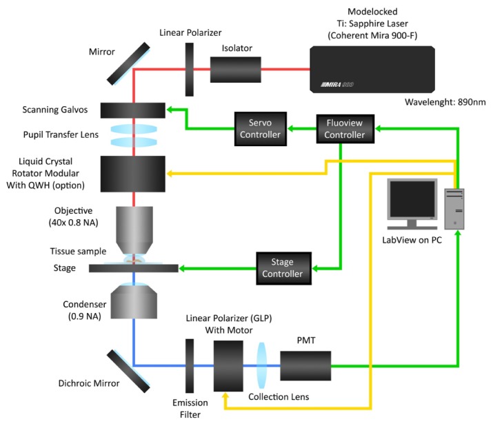
Configuration of the SHG microscope with LCM polarization control and polarization analysis.
2.3 Polarization control
High purity linear polarization was generated using a LCM (LPR-200-850, Meadowlark Optics) in the infinity space of the upright microscope. The module (created by 3D printing) containing the LCM replaced the dichroic used for backward SHG collection, therefore only forward SHG was collected in these measurements. The LCM consists of a compensated liquid crystal variable retarder combined with a zero-order polymer quarter-wave retarder. The fast axis of the former is oriented at 45° to the slow axis of the quarter-wave retarder to which the linearly polarized input must be parallel.
Polarization rotation was achieved by application of different voltages to the LCM, where a look-up table (LUT) was created, (see Fig. 2 for calibration), as the response is nonlinear. The module has a holder for an optional quarter-wave plate after the LCM, to create circular polarization at the focus. Additionally, switching the voltage to achieve 90 degree rotation affords creation of right-handed and left-handed circularly polarization (RHCP and LHCP, respectively) which is required for SHG-CD imaging measurements [33]. Moreover, it eliminates motion artifacts and other inaccuracies introduced by mechanical stage rotation as there are no moving parts. For the analysis of the polarization of the transmitted laser (for polarization calibration) or SHG signal (optionally) a removable Glan laser polarizer (GLP) is mounted on a motorized mount (Thorlabs, Inc.) before the PMT. Its transmission direction is calibrated relative to the excitation from the LCM. A custom LabVIEW program controlled the EOM, LCM, Glan-laser analyzer rotation stage and is interfaced with a data acquisition (DAQ) card (PCI-6024E, National Instruments). These devices are all synchronized with the Flouview software, which provides the master timing. The control code is available upon request.
Fig. 2.
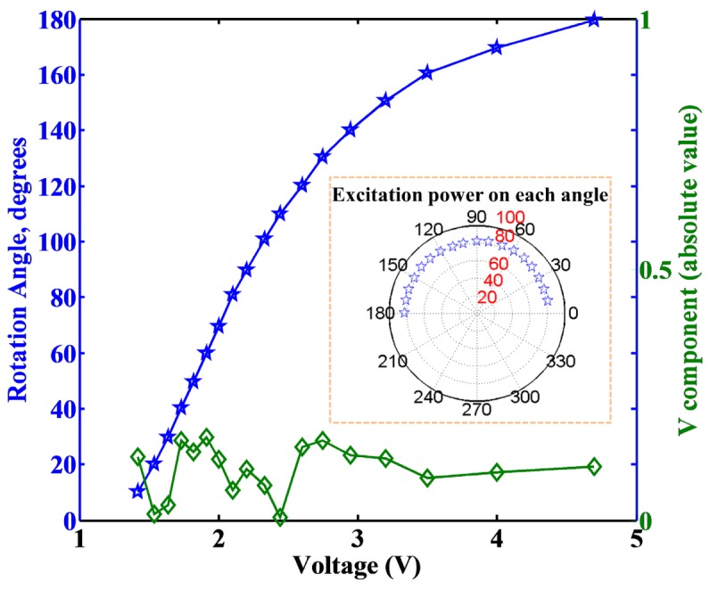
Voltage dependent rotation of the LCM and measured V component of the Stokes vector over the 0-180 degrees of linear rotation.
3. Results
3.1 Validation of polarization control and purity
We first calibrated the rotation angle relative to the applied voltage (blue line, Fig. 2) to determine the transmitted power at each angle, where the difference is smaller than 1.5%, as shown in the inset of Fig. 2. We next rigorously determined the linear polarization purity of the laser at the focus over the range of 180 degrees of rotation using the Stokes vector formalism. The four parameters of the Stokes vector are denoted I, Q, U and V (, , , and with normalized total intensity, ) in the Cartesian coordinated system and are defined as:
| (1) |
Because of the initial linear polarization from the ti:sapphire laser cavity and use of an EOM (with GLP) for power control, we can assume the fully polarized initial condition ( or ). Then we can determine the parameters in the microscope by measuring the intensity of the transmitted excitation laser (with the GLP) at 0, 45, 90, and 135 degrees relative to the chosen linear polarization in the infinity space. These measurements are made at every 10° of rotation of laser polarization angle from 0 through 180 degrees. Within the Stokes vector formalism, purely linear polarized light corresponds to V = 0, and this criterion was used to validate the polarization purity. Figure 2 shows the resulting absolute value of the V component (green line) for the rotation range of 0-180 degrees. The maximum V component was 0.17, where most values were lower, indicating high purity linear polarization was obtained at each angle. We can quantify the ellipticity for the maximum V component using the Stokes components:
| (2) |
Then the maximum ellipticity is 0.08. We note that this is an upper bound as the thermal power meter we used was not linearly sensitive at low mW measurements.
We examined the wavelength dependence of the ellipticity without changing any of the system setup. We found that that the ellipticity was similar at 830 and 890 nm, where the worst cases were 0.11 and 0.08 respectively. However, at 780 nm, the linearity was much poorer (ellipticity = 0.32). This could be improved through rotation of the LC device within the optical train and creating a new look up table for this wavelength. This suggests that the bandwidth will become an issue for very short pulses at shorter wavelengths with higher dispersion. For example, a ~10 fs pulse (with ~100 nm bandwidth) at 780 nm would result in poor linearity. However, the similarity in ellipticity between the 830 and 890 data conservatively suggests that 50 femtosecond pulses (~20 nm FWM) could readily be used.
3.2 Imaging validation with specimens of known symmetry
3.2.1 Imaging giant unilamellar vesicles possessing cylindrical symmetry
We verified the performance of the linear and circular polarization control first by two-photon excited fluorescence (TPEF) of GUVs stained with the membrane dye Di-8-ANEPPS. In this case the TPEF and SHG are nearly equivalent but the relative intensity of the former is higher and thus we chose this modality for convenience. By the electric dipole interaction, the absorption (or SHG) will be maximized when the dipole moment of the dye is aligned with the laser polarization [34, 35]. This dye inserts perpendicular to the plane of membrane, thus the image from a cylindrically symmetric vesicle will be parallel “arcs” aligned with the polarization. The results for a 40 µm diameter GUV are shown in Fig. 3(a) (left), where images are shown for every 10° of linear rotation from 0 to 180 degrees. The polarization resolved images of the GUV matched the excited polarization angles (white arrows) as determined by the Stokes parameters described above, and the “arcs” rotated correspondingly, where for example 0 and 90° are seen to be orthogonal patterns. For a quadratic process, the dependence of the fluorescence intensity as a function of polarization angle, ϴ, for a fixed single axis molecule is given by the expression:
Fig. 3.
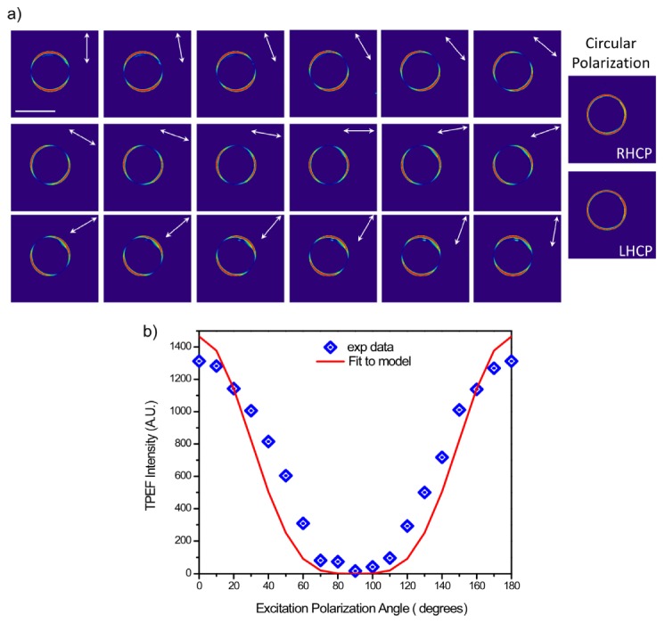
3(a) TPEF linear (left) and circular (right) polarization responses of a GUV labeled with Di-8-ANEPPS. Scale bar = 40 microns. 3(b) The measured TPEF polarization dependent intensity is fit to the theoretical response for a quadratic process.
| (3) |
In Fig. 3(b), we have shown that the measured response for the images of the GUV in Fig. 3(a) can be well-fit to this model (R2 = 0.87), where the intensity was averaged over 9 pixels. The best fit occurs in the vicinity of 90 degrees, which is the minimal value of V, and conversely the largest errors roughly correspond to angles with larger values. We note that the ideal ellipticity i.e. V = 0, was not achievable at all angles. These values were determined without an objective in the path and the errors are likely due to differences in retardance arising from the different angles of incidence in laser scanning. The fluorescence data has additional potential sources of error including strain from the objective and birefringence in the dichroic before the detector (this was detected in the transmission geometry).
Circular polarization is achieved through the addition of a λ/4 plate following the LCM, and the left and right handed circularly polarized light images are shown in the right panel of Fig. 3(a). The even ring stain indicates all orientations are excited equally, showing circular polarization is maintained at the focal plane. Moreover, the images from RHCP and LHCP are equivalent, indicating any residual ellipticity is minimal.
3.2.2 SHG imaging of rat tail tendon
We next performed SHG polarization analysis with a rat tail tendon, as this specimen has a well-defined polarization response due to the highly aligned fibers [19]. As the tendon is sufficiently thick to support multiple scattering events which randomize the polarization response, the specimen must be first optically cleared to reduce the scattering and increase the transparency [31]. Here we define 0° condition as where the laser polarization is aligned with the long axis of a collagen fiber(s). Figure 4(a) shows single optical sections at 0, 40, 90, and 140 degrees, where these were chosen as we previously showed they are the local maxima and minima in the polarization response [19]. Figure 4(b) shows the normalized polarization response of the SHG intensity (averaged over whole fields of view (5)) for images acquired at 5 degree intervals through 180° of rotation. We note this analysis can be performed this way as opposed to on a fiber by fiber or pixel by pixel basis as all the fibers in the field of view have the same orientation. The maxima and minima overlap with our previous results. We have shown that this response can be fit to a single molecular axis model yielding the α-helix pitch angle [19]:
| (4) |
where N is the number density of the elemental dipoles, P is the induced polarization, and the three parameters a, b, and c are numerical coefficients related to the non-vanishing matrix elements of χ(2). The fit is overlapped with the experimental data in Fig. 4(b). Based on this model we extracted an angle of 50.7°, in good agreement with our previous findings (50.7°) [19]. We also note that although V≠0 at all polarization angles (Fig. 2), there are no asymmetries or systematic deviations in the response over the 180 degrees of linear rotation.
Fig. 4.
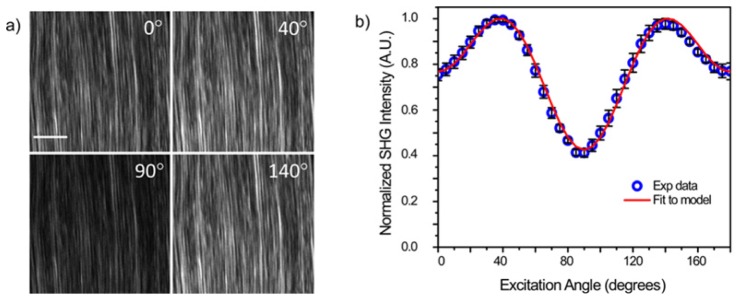
(a) Single SHG optical sections from rat tail tendon. The scale bar is 20 um. (b) SHG intensity as a function of polarization range and the fit to the single axis mode. The error bars are standard deviations.
3.2.3 SHG imaging of skeletal muscle
We next demonstrate the polarization control with the LCM for SHG imaging of skeletal muscle, where this specimen is also a good test case as the sarcomeres are highly aligned with myofibrils. Leg muscle was sectioned to 100 µm of thickness using a Vibratome and optically cleared overnight in 50% glycerol-PBS solution. As in tendon, the laser polarization is aligned with the long axis of the fiber (s), defining the 0° point. Figure 5(a) shows single optical sections at 0, 50, 90 and 130° excitation, where, as in tendon, these are the local maxima and minima in the polarization response [19]. Figure 5(b) shows the normalized polarization response of the SHG intensity (averaged over the whole field of view (n = 5)) for images acquired at 5 degree intervals. The data is fit to the single axis molecular model and we extracted an angle of 60.5°, in good agreement with our previous finding of 61.2° at this wavelength [19].
Fig. 5.
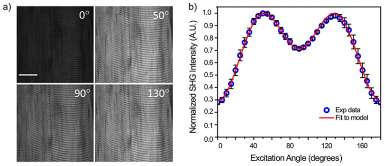
(a) Single SHG optical sections from rat tail skeletal muscle. The scale bar is 20 um. (b) SHG intensity as a function of polarization range and the fit to the single axis mode. The error bars are standard deviations.
3.2.4 SHG-CD imaging of tendon
We lastly demonstrate the performance of the LCM by imaging the SHG circular dichroism (SHG-CD) of tendon. Conventional linear circular dichroism is a standard tool for studying protein folding as it results from differential absorption of right and left handed circular polarized light due to the intrinsic handedness of protein helices. We recently reported SHG-CD imaging, where we similarly showed a differential SHG response with right and left handed circularly polarized (RH-CP and LH-CP, respectively) excitation in tendon and skin [33]. In that configuration, all the polarization optics were all outside the microscope. To quantify this data, we defined the normalized SHG-CD as |IRHCP-ILHCP|/((IRHCP + ILHCP)/2), where IRHCP and ILHCP are the integrated intensity of the SHG images for RHCP and LHCP excitation respectively. We found a 5% intensity response in optically cleared tendon. The analogous results using the current approach are shown in Fig. 6 , showing the SHG from RH-CP and LH-CP and their difference. Here we also found a 5% difference in normalized SHG-CD, where this similarity validates the new approach and also demonstrates the ability to reveal relatively small changes.
Fig. 6.
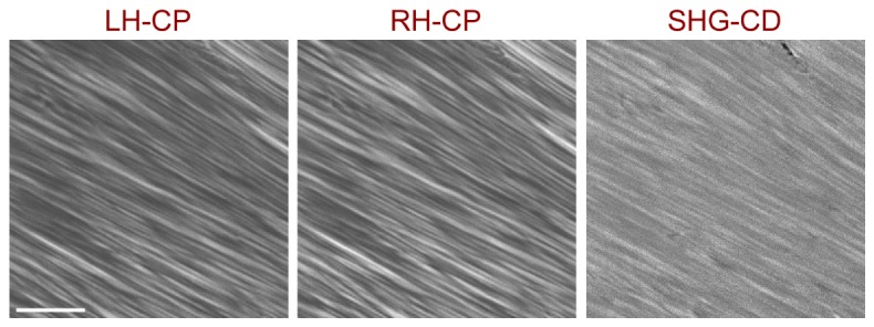
SHG-CD imaging of optically cleared tendon, showing the RH-CP and LH-CP SHG images and the resulting difference image (SHG-CD). Scale bar = 40 microns.
4. Discussion
4.1 Performance
There are several index parameters to describe the polarization state, polarization purity, or ellipticity. Polarization purity is defined as the ratio of the rotated linear component to the orthogonal component, where ellipticity (Eq. (2)) also includes the circular polarization attributes. Based on this concept, measuring only two components is not sufficient for calibration of the polarization rotation (both linear and circular) set-up. We used the Stokes polarimetry method in section 3.1 and in particular chose the V component to serve as the parameter index of the polarization state because it is sensitive to the ellipticity of each desired linear polarization state. Other sources of distortion include the scanning galvo mirror pair, and some defects or residual birefringence in the liquid crystal cell itself. However, the ellipticity was 0.08 for the maximum V component (0.17), indicating that the remaining polarization distortions were minimal and acceptable. This is also supported by the imaging data and fits in Figs. 3-5, all of which show the expected behavior for high polarization purity. While the polarization is defined in the infinity space, little polarization scrambling will occur at the NA used here (0.8), where this effect only becomes significant for NA>1 [36]. As most tissue imaging is done at moderate NA to achieve working distance, defining the polarization in this location is not limiting.
4.2 Advantages of the method
The presented method of polarization control has advantages over existing methods in terms of speed and precision. The approach of having the LCM in the infinity space is more accurate and convenient than rotating the polarization outside the microscope, as birefringence in the system will result in erroneous states at the focus. This is also simpler than finding a solution for every desired polarization state [27, 28]. We note that Oldenbourg first used liquid crystals to achieve universal compensation in the PolScope in 1995 [37]. That work demonstrated proof of principle, where, in a wide-field configuration, two devices are located between the arc lamp and condenser. Our approach starting with linearly polarized laser excitation is simpler as it requires only one device and is implementable in any laser scanning microscope.
While our approach achieves the same result as fixing the polarization and mechanically rotating the specimen, the LCM is motion free and faster than stepper motors which have inertia and substantial associated stabilization time with each movement and can require more than a second in between measurements. In contrast this LCM has a conservative response time of ~30 ms for the rotation step sizes used here (e.g. 10 degrees). Similarly, waveplates under motorized control located within the microscope have been used successfully, but this approach is also limited by rotation speed and potential vibrational artifacts. In our configuration laser scanning becomes the rate limiting step.
We note that an EOM in the infinity space could also be used in lieu of the LCM. This would have the advantage that the rotation vs. applied voltage is fairly linear, whereas the LCM requires generation of a look-up table. However, EOMS are typically larger and will not fit in the infinity space without significant modifications, whereas the LCM is a much smaller footprint device. Additionally, LCMs are more cost effective than EOMs. We also note that while the liquid crystal maximum driving frequency is lower than an EOM, it is more than sufficient for scanning microscopy.
4.3 Applications
Here we demonstrated the polarization response images of stained GUVs, rat tail tendon, and skeletal muscle for basic linear and circular polarization imaging. In addition, this setup system may also be used for sequential different SHG polarization measurements in the same optical section of the tissue, such as SHG circular dichroism (CD) [33] and SHG anisotropy with different excitation angles. Moreover, adding a quarter wave plate or LCM in the collection pathway, we can determine the Mueller matrix of the tissue for further characterization [38]. We note that the analysis here was performed for well-aligned tissues by averaging over the field of view, the instrumentation is also applicable to perform pixel-based analysis for more complex morphologies such as that recently presented by Brasselet and associates [39].
To date, most SHG polarization measurements have been primarily used as tools to probe tissue properties in well-aligned specimens such as tendon and muscle. However, there remains great potential in using detailed polarization analysis to classify normal and diseased tissues, such as cancer and connective tissue disorders, which often have different fibrillar properties. For example, we showed that the SHG anisotropy [40] and SHG-CD responses [33] in the connective tissue disorder Osteogenesis imperfecta (OI) were different than in normal tissues. We also recently showed that SHG polarization signatures could differentiate different collagen isoforms in self-assembled collagen gels which are models for stromal changes in ovarian cancer (Biophysical Journal, submitted).
5. Conclusions
We have implemented a new means of polarization control for SHG microscopy, based on using a LCM located in the infinity space. This provides a rapid and precise means of achieving any desired linear or circular polarization state at the focus of the microscope, and the motion free approach has advantages over previous implementations using mechanical rotation of waveplates or the specimen. The performance was verified using Stokes vector polarimetry and SHG imaging of specimens with well-defined circular and/or linear symmetries. The imaging experiments and analysis were all consistent with previous work on these specimens. We suggest that due to ease of implementation speed and precision, this approach may pave the way for further use of SHG polarization measurements. For example, this may better enable classification of normal and diseased tissues for several pathologies which have changes in ECM structure.
Acknowledgments
We gratefully acknowledge support under National Cancer Institute R01 CA136590-01A1, KT acknowledges support under 5T32CA009206-34. We thank Mr. Jorge Lara for help in preparing figures.
References and links
- 1.Campagnola P. J., Millard A. C., Terasaki M., Hoppe P. E., Malone C. J., Mohler W. A., “Three-dimensional high-resolution second-harmonic generation imaging of endogenous structural proteins in biological tissues,” Biophys. J. 82(1), 493–508 (2002). 10.1016/S0006-3495(02)75414-3 [DOI] [PMC free article] [PubMed] [Google Scholar]
- 2.Lo W., Teng S. W., Tan H. Y., Kim K. H., Chen H. C., Lee H. S., Chen Y. F., So P. T. C., Dong C. Y., “Intact corneal stroma visualization of GFP mouse revealed by multiphoton imaging,” Microsc. Res. Tech. 69(12), 973–975 (2006). 10.1002/jemt.20373 [DOI] [PubMed] [Google Scholar]
- 3.Provenzano P. P., Inman D. R., Eliceiri K. W., Knittel J. G., Yan L., Rueden C. T., White J. G., Keely P. J., “Collagen density promotes mammary tumor initiation and progression,” BMC Med. 6(1), 11 (2008). 10.1186/1741-7015-6-11 [DOI] [PMC free article] [PubMed] [Google Scholar]
- 4.Chen S. Y., Chen S. U., Wu H. Y., Lee W. J., Liao Y. H., Sun C. K., “In Vivo virtual biopsy of human skin by using noninvasive higher harmonic generation microscopy,” IEEE J. Sel. Top. Quantum Electron. 16(3), 478–492 (2010). 10.1109/JSTQE.2009.2031987 [DOI] [Google Scholar]
- 5.Brown E., McKee T., diTomaso E., Pluen A., Seed B., Boucher Y., Jain R. K., “Dynamic imaging of collagen and its modulation in tumors in vivo using second-harmonic generation,” Nat. Med. 9(6), 796–801 (2003). 10.1038/nm879 [DOI] [PubMed] [Google Scholar]
- 6.Cicchi R., Sestini S., De Giorgi V., Carli P., Massi D., Pavone F. S., “Basal cell carcinoma imaging and characterization by multiple nonlinear microscopy techniques,” Biophys. J. 157a–157a (2007). [Google Scholar]
- 7.Strupler M., Pena A. M., Hernest M., Tharaux P. L., Martin J. L., Beaurepaire E., Schanne-Klein M. C., “Second harmonic imaging and scoring of collagen in fibrotic tissues,” Opt. Express 15(7), 4054–4065 (2007). 10.1364/OE.15.004054 [DOI] [PubMed] [Google Scholar]
- 8.Pfeffer C. P., Olsen B. R., Légaré F., “Second harmonic generation imaging of fascia within thick tissue block,” Opt. Express 15(12), 7296–7302 (2007). 10.1364/OE.15.007296 [DOI] [PubMed] [Google Scholar]
- 9.Brockbank K. G., MacLellan W. R., Xie J., Hamm-Alvarez S. F., Chen Z. Z., Schenke-Layland K., “Quantitative second harmonic generation imaging of cartilage damage,” Cell Tissue Bank. 9(4), 299–307 (2008). 10.1007/s10561-008-9070-7 [DOI] [PubMed] [Google Scholar]
- 10.Kwon G. P., Schroeder J. L., Amar M. J., Remaley A. T., Balaban R. S., “Contribution of macromolecular structure to the retention of low-density lipoprotein at arterial branch points,” Circulation 117(22), 2919–2927 (2008). 10.1161/CIRCULATIONAHA.107.754614 [DOI] [PMC free article] [PubMed] [Google Scholar]
- 11.Plotnikov S. V., Kenny A. M., Walsh S. J., Zubrowski B., Joseph C., Scranton V. L., Kuchel G. A., Dauser D., Xu M., Pilbeam C. C., Adams D. J., Dougherty R. P., Campagnola P. J., Mohler W. A., “Measurement of muscle disease by quantitative second-harmonic generation imaging,” J. Biomed. Opt. 13(4), 044018 (2008). 10.1117/1.2967536 [DOI] [PubMed] [Google Scholar]
- 12.Nucciotti V., Stringari C., Sacconi L., Vanzi F., Fusi L., Linari M., Piazzesi G., Lombardi V., Pavone F. S., “Probing myosin structural conformation in vivo by second-harmonic generation microscopy,” Proc. Natl. Acad. Sci. U.S.A. 107(17), 7763–7768 (2010). 10.1073/pnas.0914782107 [DOI] [PMC free article] [PubMed] [Google Scholar]
- 13.Campagnola P., “Second harmonic generation imaging microscopy: applications to diseases diagnostics,” Anal. Chem. 83(9), 3224–3231 (2011). 10.1021/ac1032325 [DOI] [PMC free article] [PubMed] [Google Scholar]
- 14.Cicchi R., Kapsokalyvas D., De Giorgi V., Maio V., Van Wiechen A., Massi D., Lotti T., Pavone F. S., “Scoring of collagen organization in healthy and diseased human dermis by multiphoton microscopy,” J Biophotonics 3(1-2), 34–43 (2010). 10.1002/jbio.200910062 [DOI] [PubMed] [Google Scholar]
- 15.Pena A. M., Fabre A., Débarre D., Marchal-Somme J., Crestani B., Martin J. L., Beaurepaire E., Schanne-Klein M. C., “Three-dimensional investigation and scoring of extracellular matrix remodeling during lung fibrosis using multiphoton microscopy,” Microsc. Res. Tech. 70(2), 162–170 (2007). 10.1002/jemt.20400 [DOI] [PubMed] [Google Scholar]
- 16.Sun W., Chang S., Tai D. C., Tan N., Xiao G., Tang H., Yu H., “Nonlinear optical microscopy: use of second harmonic generation and two-photon microscopy for automated quantitative liver fibrosis studies,” J. Biomed. Opt. 13(6), 064010 (2008). 10.1117/1.3041159 [DOI] [PubMed] [Google Scholar]
- 17.Conklin M. W., Eickhoff J. C., Riching K. M., Pehlke C. A., Eliceiri K. W., Provenzano P. P., Friedl A., Keely P. J., “Aligned collagen is a prognostic signature for survival in human breast carcinoma,” Am. J. Pathol. 178(3), 1221–1232 (2011). 10.1016/j.ajpath.2010.11.076 [DOI] [PMC free article] [PubMed] [Google Scholar]
- 18.Ghazaryan A., Tsai H. F., Hayrapetyan G., Chen W. L., Chen Y. F., Jeong M. Y., Kim C. S., Chen S. J., Dong C. Y., “Analysis of collagen fiber domain organization by Fourier second harmonic generation microscopy,” J. Biomed. Opt. 18(3), 031105 (2013). 10.1117/1.JBO.18.3.031105 [DOI] [PubMed] [Google Scholar]
- 19.Plotnikov S. V., Millard A. C., Campagnola P. J., Mohler W. A., “Characterization of the myosin-based source for second-harmonic generation from muscle sarcomeres,” Biophys. J. 90(2), 693–703 (2006). 10.1529/biophysj.105.071555 [DOI] [PMC free article] [PubMed] [Google Scholar]
- 20.Tuer A. E., Krouglov S., Prent N., Cisek R., Sandkuijl D., Yasufuku K., Wilson B. C., Barzda V., “Nonlinear optical properties of type I collagen fibers studied by polarization dependent second harmonic generation microscopy,” J. Phys. Chem. B 115(44), 12759–12769 (2011). 10.1021/jp206308k [DOI] [PubMed] [Google Scholar]
- 21.Gusachenko I., Latour G., Schanne-Klein M. C., “Polarization-resolved Second Harmonic microscopy in anisotropic thick tissues,” Opt. Express 18(18), 19339–19352 (2010). 10.1364/OE.18.019339 [DOI] [PubMed] [Google Scholar]
- 22.Gusachenko I., Tran V., Houssen Y. G., Allain J. M., Schanne-Klein M. C., “Polarization-resolved second-harmonic generation in tendon upon mechanical stretching,” Biophys. J. 102(9), 2220–2229 (2012). 10.1016/j.bpj.2012.03.068 [DOI] [PMC free article] [PubMed] [Google Scholar]
- 23.Rouède D., Bellanger J. J., Schaub E., Recher G., Tiaho F., “Theoretical and experimental SHG angular intensity patterns from healthy and proteolysed muscles,” Biophys. J. 104(9), 1959–1968 (2013). 10.1016/j.bpj.2013.02.047 [DOI] [PMC free article] [PubMed] [Google Scholar]
- 24.Su P. J., Chen W. L., Chen Y. F., Dong C. Y., “Determination of collagen nanostructure from second-order susceptibility tensor analysis,” Biophys. J. 100(8), 2053–2062 (2011). 10.1016/j.bpj.2011.02.015 [DOI] [PMC free article] [PubMed] [Google Scholar]
- 25.Chu S.-W., Chen S.-Y., Chern G.-W., Tsai T.-H., Chen Y.-C., Lin B.-L., Sun C.-K., “Studies of chi(2)/chi(3) tensors in submicron-scaled bio-tissues by polarization harmonics optical microscopy,” Biophys. J. 86(6), 3914–3922 (2004). 10.1529/biophysj.103.034595 [DOI] [PMC free article] [PubMed] [Google Scholar]
- 26.Brasselet S., “Polarization resolved nonlinear microscopy: application to structural molecular and biological imaging,” Adv. Opt. Photon. 3(3), 205–271 (2011). 10.1364/AOP.3.000205 [DOI] [Google Scholar]
- 27.Chou C. K., Chen W. L., Fwu P. T., Lin S. J., Lee H. S., Dong C. Y., “Polarization ellipticity compensation in polarization second-harmonic generation microscopy without specimen rotation,” J. Biomed. Opt. 13(1), 014005 (2008). 10.1117/1.2824379 [DOI] [PubMed] [Google Scholar]
- 28.Schön P., Munhoz F., Gasecka A., Brustlein S., Brasselet S., “Polarization distortion effects in polarimetric two-photon microscopy,” Opt. Express 16(25), 20891–20901 (2008). 10.1364/OE.16.020891 [DOI] [PubMed] [Google Scholar]
- 29.Chen X., Nadiarynkh O., Plotnikov S., Campagnola P. J., “Second harmonic generation microscopy for quantitative analysis of collagen fibrillar structure,” Nat. Protoc. 7(4), 654–669 (2012). 10.1038/nprot.2012.009 [DOI] [PMC free article] [PubMed] [Google Scholar]
- 30.Tiaho F., Recher G., Rouède D., “Estimation of helical angles of myosin and collagen by second harmonic generation imaging microscopy,” Opt. Express 15(19), 12286–12295 (2007). 10.1364/OE.15.012286 [DOI] [PubMed] [Google Scholar]
- 31.Nadiarnykh O., Campagnola P. J., “Retention of polarization signatures in SHG microscopy of scattering tissues through optical clearing,” Opt. Express 17(7), 5794–5806 (2009). 10.1364/OE.17.005794 [DOI] [PMC free article] [PubMed] [Google Scholar]
- 32.Sandre O., Moreaux L., Brochard-Wyart F., “Dynamics of transient pores in stretched vesicles,” Proc. Natl. Acad. Sci. U.S.A. 96(19), 10591–10596 (1999). 10.1073/pnas.96.19.10591 [DOI] [PMC free article] [PubMed] [Google Scholar]
- 33.Chen X. Y., Raggio C., Campagnola P. J., “Second-harmonic generation circular dichroism studies of osteogenesis imperfecta,” Opt. Lett. 37(18), 3837–3839 (2012). 10.1364/OL.37.003837 [DOI] [PMC free article] [PubMed] [Google Scholar]
- 34.Millard A. C., Jin L., Wei M. D., Wuskell J. P., Lewis A., Loew L. M., “Sensitivity of second harmonic generation from styryl dyes to transmembrane potential,” Biophys. J. 86(2), 1169–1176 (2004). 10.1016/S0006-3495(04)74191-0 [DOI] [PMC free article] [PubMed] [Google Scholar]
- 35.Moreaux L., Sandre O., Charpak S., Blanchard-Desce M., Mertz J., “Coherent scattering in multi-harmonic light microscopy,” Biophys. J. 80(3), 1568–1574 (2001). 10.1016/S0006-3495(01)76129-2 [DOI] [PMC free article] [PubMed] [Google Scholar]
- 36.Axelrod D., “Carbocyanine dye orientation in red cell membrane studied by microscopic fluorescence polarization,” Biophys. J. 26(3), 557–573 (1979). 10.1016/S0006-3495(79)85271-6 [DOI] [PMC free article] [PubMed] [Google Scholar]
- 37.Oldenbourg R., Mei G., “New polarized light microscope with precision universal compensator,” J. Microsc. 180(2), 140–147 (1995). 10.1111/j.1365-2818.1995.tb03669.x [DOI] [PubMed] [Google Scholar]
- 38.Wang X., Wang L. V., “Propagation of polarized light in birefringent turbid media: a Monte Carlo study,” J. Biomed. Opt. 7(3), 279–290 (2002). 10.1117/1.1483315 [DOI] [PubMed] [Google Scholar]
- 39.Duboisset J., Ait-Belkacem D., Roche M., Rigneault H., Brasselet S., “Generic model of the molecular orientational distribution probed by polarization-resolved second-harmonic generation,” Phys. Rev. A 85(4), 043829 (2012). 10.1103/PhysRevA.85.043829 [DOI] [Google Scholar]
- 40.Nadiarnykh O., Plotnikov S., Mohler W. A., Kalajzic I., Redford-Badwal D., Campagnola P. J., “Second harmonic generation imaging microscopy studies of Osteogenesis Imperfecta,” J. Biomed. Opt. 12(5), 051805 (2007). 10.1117/1.2799538 [DOI] [PubMed] [Google Scholar]


