Abstract
Introduction:
The replacement of missing anterior teeth presents peculiar challenges to the Prosthodontist. Implants are increasingly gaining favour for the same. The morphology of existing bone in the premaxilla often dictates that implants are placed at angles that are difficult to restore with conventional abutments. However, the angulated abutments might transfer unfavourable forces to the implant or bone, thereby compromising the prognosis of the treatment. Because, it is difficult to assess the generated forces clinically, a finite element analysis was chosen for the present study as it is useful tool in estimating stress distribution in the contact area of the implant with the bone.
Materials and Methods:
In this study, the frontal region of the maxilla was modelled with a cortical layer 1.5 mm thick containing an inner cancellous core. The implant was cylindrical, round ended, with length 13 mm and diameter 4.1 mm. The abutment was modelled as 7 mm in height with a 5 degree occlusal taper. The different abutment angulations used were 0°, 10°, 15° and 20°. The amount of loads used were 100, 125, 150, 175 and 200 N axially, and 50 N in oblique direction, to approximate the kind of loads seen in clinical situations.
Result:
It was seen that, as the abutment angulation changes from 0° to 20° both the compressive as well as tensile stresses increased; but, it is within the tolerance limit of the bone.
Conclusion:
It seems reasonably safe to use angled abutments in anterior implant supported prostheses, in the maxillary arch.
Keywords: Angled implant abutment, dental implant, finite element analysis, maxilla, osseointegration, stress analysis
INTRODUCTION
The replacement of missing anterior teeth presents challenges to the Prosthodontist regarding esthetics and function. Implant supported prosthesis for missing anterior teeth are increasingly finding acceptance in the present day treatment options. The morphology of existing bone in the premaxilla often dictates that implants be placed at angles that are difficult to restore with conventional (0°) abutments. Angled implants are often used in single tooth replacements in the anterior region of the maxilla, distal extension cases in the maxillary and/or mandibular arch, overdentures in the edentulous maxilla and occasional anatomic problems for placement of straight implants.[1,2] However, the angulated abutments might transfer unfavourable forces to the implant or bone, thereby compromising the prognosis of the treatment. The angulation of the implant abutments is one of the many biomechanical variables involved in implant dentistry.[3]
During the prosthetic phase, in order to have a well-designed, functioning and esthetic supra-structure, angulated abutments are used. However, due to a change between the long axis of the supra-structure, and the implant, the stresses generated in response to the masticatory or vertical load may be different in type, magnitude and direction. This may result in resorption of the bone at the cervical cortical region or loss of osseointegration.[4,5,6] There is surprisingly little information in the available literature regarding the clinical success of angled abutments. Hence, it was considered appropriate to undertake the study of stresses generated having different angulations to the long axis of the implant, under axial and oblique loading, by Finite Element Modelling and Analysis.[6,7,8] Because, it is difficult to assess the generated forces clinically, a finite element analysis was chosen for the present study as it is a useful tool in estimating stress distribution in the contact area of the implant with the bone.
MATERIALS AND METHODS
The three dimensional (3D) Finite Element Analysis study was conducted in the Post Graduate Department Of Prosthodontics, Sardar Patel Post Graduate Institute of Dental and Medical Sciences, Lucknow - in collaboration with - Lelogix design solutions private Limited, Greater Noida, Uttar Pradesh using the software package solid works 2009 [Figure 1a and 1b]. Maxillary bone was modelled representing the frontal region of the maxilla with a cortical bone of 1.5 mm thickness enclosing cancellous core. Properties approximating D3 bone were used. (65% of bone found in anterior maxilla).[9] Implant was modelled as a cylindrical, round ended, 13 mm long with 4.1 mm diameter. Abutment was modelled as 7 mm in height with a five degree occlusal taper [Table 1]. Finite Element mesh was generated by a network of fine elements or nodes [Table 2], [Figures 2a-c] and then the mechanical properties of the material were assigned [Table 3].[10] Four different abutment angulations, respectively 00 , 100 , 150 and 200 were used. These were then subjected to axial and oblique loadings. The magnitude of force in the axial loading was 100 N, 125 N, 150 N, 175 N, and 200 N. The oblique loading was kept constant at 50 N [Figure 3]. The loading was based on the average axial/oblique loading observed in the natural dentition by different researchers.[11,12] To prevent the movement of the model during loading, the base was fixed [Figure 4].
Figure 1a.
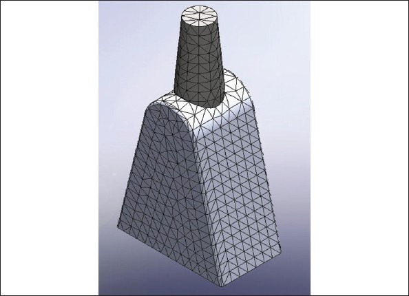
Model of Straight abutment (Solid works 2009 software)
Figure 1b.
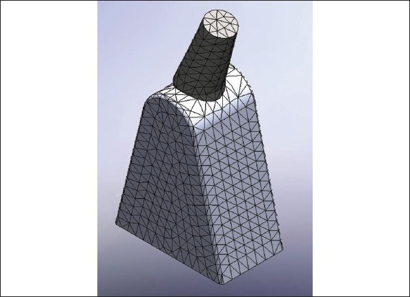
Model of angulated abutment (Solid works 2009 software)
Table 1.
List of parameters used in FEA study
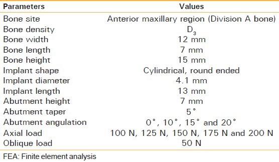
Table 2.
Number of elements and nodes modelled for the bone

Figure 2a.
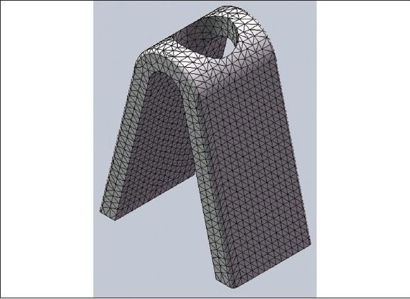
Mesh of Cortical Bone
Figure 2c.
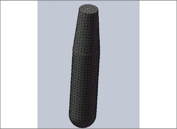
Mesh of Implant
Table 3.
Material properties used in finite element analysis

Figure 3.
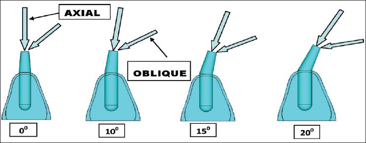
Directions of load application (Axial and oblique)
Figure 4.
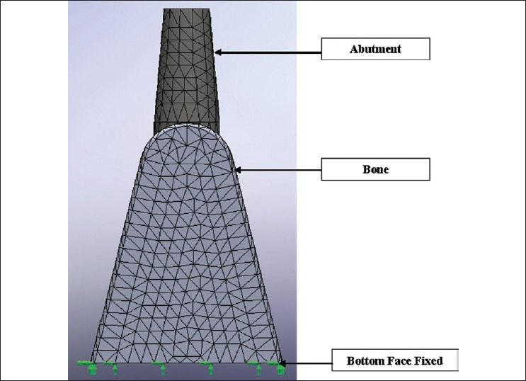
Boundary conditions
Figure 2b.
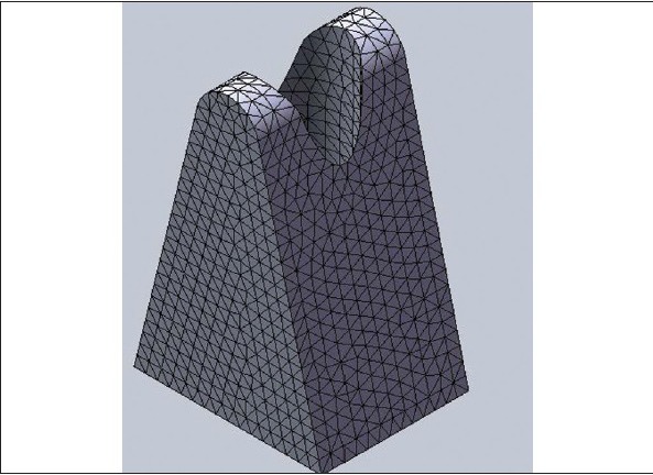
Mesh of Cancellous Bone
OBSERVATIONS AND RESULTS
Stresses were interpreted as compressive and tensile and were evaluated within the bone. Four groups of models were analyzed. In the first group, the implant was placed in the section of the bone and the 0° abutment was placed onto it, and the von misses, compressive and tensile stresses were calculated. Similarly, in the second and third and fourth groups, 10°, 15° and 20° abutments were used on the same implant configuration and the same load was applied to the implant [Tables 4 and 5], [Figure 5a and b].
Table 4.
Compressive stress and tensile stress under axial loading
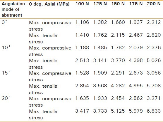
Table 5.
Compressive stress and tensile stress for 50 N force under oblique loading
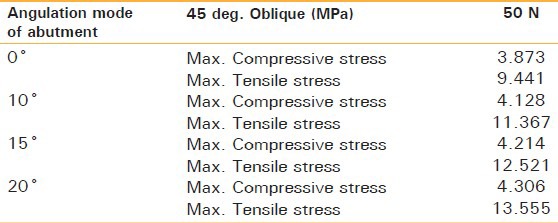
Figure 5a.
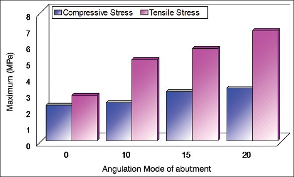
Compressive stress and tensile stress for 200 N Force at 0 degree axial loading
Figure 5b.
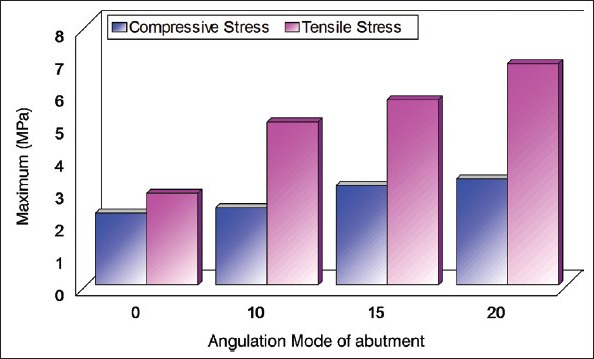
Compressive stress and tensile stress for 50 N Force at 45 degree oblique loading
DISCUSSION
Implant dentistry has established itself as the epitome of modern dentistry. Almost all surgically indicated cases are treated with implants nowadays. This treatment modality, though highly successful, comes with its share of failures. The most common complications in implant dentistry once the prosthesis is placed are bone loss, fracture of the occlusal materials or implant components.[13,14] An implant, placed in improper position, can compromise the final result in esthetics, biomechanics and hygiene maintenance. The most compromising position for an implant is, when placed too far facially: Phonetics, lip position and function are compromised.[12] An angled abutment may come to our rescue in such situations. Changing its angulation may have a bearing on the kind of loads transferred to the bone. This study was conducted to gain more insight into the influence of different angulated implant abutments on the stress distribution in the alveolar bone surrounding the implant both, under axial and oblique loading.
The stresses can be evaluated by using one of the following methodologies:
Photoelastic method
Strain gauge analysis
Finite Element Method/Analysis.
The Finite Element Analysis is capable of providing detailed quantitative and qualitative data at any location within the mathematical model. The finite element analysis was chosen for the present study as it has proved to be a useful tool in estimating stress distribution in the contact area of the implant with cortical bone and around the apex of the implant in trabecular bone. The Finite Element Analysis (FEA) has been established as a standardized procedure for qualitative as well as quantitative assessment of the stress distribution in various structures. With the FEA, the mechanical behaviour of the bone and implant system can be evaluated. The validity of the FEA results depends on the precision, whether the geometry, the material proportion, the interface condition, support and loading are in accordance with the biomechanical reality and the mathematical modelling should be verified by actual experiment in order to verify the findings of the result. In the results both numerical and graphical values were generated. For principle stresses, the negative values assigned were that of the compressive stresses and positive for tensile stresses. These principle stresses were represented in units of megapascal (Mpa). A similar study was done by Celland et al.[15] in which axial loading of 178 N only was used. Their results could be compared with the findings of the current study for 200 N axial loading since; it is nearest to the loading conditions used in the current study [Figure 6a and b]. It was observed that the maximum compressive stresses for 20° abutment were about 3.271 Mpa in the present study whereas their value was about 5.0 Mpa. For tensile stresses their observed value was about 2 Mpa as compared to the value of approximate 6.833 Mpa in the current study. The slight variation could be attributed to the change in geometry, amount of loads applied and difference in the bone density. On comparing the location of stresses it was seen that as the abutment angulation increased from 0° to 20°, the concentration of stresses shifted to the cortical bone which was a consistent finding in both the studies. It was seen that there was an increment in compressive stress in proportion to the force being used and the changes were statistically significant whereas in case of tensile stress, though an increment was observed on increasing the force, this was not a proportional or significant change. On analysis of the results it was seen that as the abutment angulation is increased there is an increase in stresses, both tensile and compressive. The increase observed was found in both the axial as well as oblique loading. However the magnitude of tensile stresses under oblique loading was found to be the greatest of all. On assessing the location of these peak stresses as the angulation changes it was observed that the peaks were located in the region of cortical bone. On taking the physiological limit of bone to be 170 Mpa for compressive stress and 100 N for tensile stress for compact bone and 2 to 5 Mpa for both compressive and tensile stresses in trabecular bone.[16] These limits are not seen to be exceeded in general. Only high levels of oblique loading for abutment angulations 20° were seen to be exceeding these limits. In general the use of angulated abutments seems to be well tolerated. However, the component of oblique load should be kept to a minimum while designing restorations, as these forces were seen to be the ones which could be detrimental to the maintenance of bone around implants.
Figure 6a.
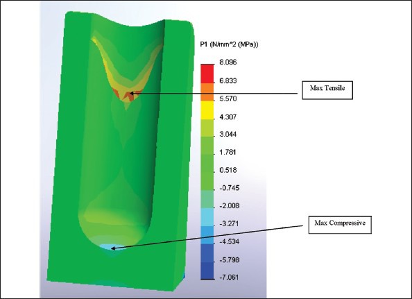
200 N force under axial loading 20° abutments (Front view)
Figure 6b.
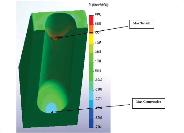
200 N force under axial loading 20° abutments (Top view)
Though the location and magnitude of stresses generated in response to the load applied in the study are pertaining to the Finite Element model design of the study, yet limitations of modelling assumptions should also be considered as the nature of the material used for the study model as well as the static loads applied in the current study may vary from the heterogenous nature of the bone and dynamic chewing forces generated clinically. Hence, further research using 3D FEA combined with long term clinical evaluation is encouraged.
CONCLUSIONS
On the basis of the observations, of a three dimensional Finite Element Analysis to access stress pattern in different abutment angulations, it can be concluded that though the compressive and tensile stresses generated through axial and oblique loading increase as the abutment angulation increases yet they are within the tolerance limits of the bone. However, care should be taken while planning a restoration so as to minimize the oblique component of force.
Footnotes
Source of Support: Nil
Conflict of Interest: None declared
REFERENCES
- 1.Ten Bruggenkate CM, Sutter F, Oosterbeek HS, Schroeder A. Indications for angled implants. J Prosthet Dent. 1992;67:85–93. doi: 10.1016/0022-3913(92)90056-g. [DOI] [PubMed] [Google Scholar]
- 2.Eger DE, Gunsolley JC, Feldman S. Comparison of angled and standard abutments and their effect on clinical outcomes: A preliminary report. Int J Oral Maxillofac Implants. 2000;15:819–23. [PubMed] [Google Scholar]
- 3.Clelland NL, Gilat A, McGlumphy EA, Brantley WA. A photoelastic and strain gauge analysis of angled abutments for an implant system. Int J Oral Maxillofac Implants. 1993;8:541–8. [PubMed] [Google Scholar]
- 4.Eskitascioglu G, Usumez A, Sevimay M, Soykan E, Unsal E. The influence of occlusal loading location on stresses transferred to implant supported prosthesis and supporting bone: A three dimensional finite element study. J Prosthet Dent. 2004;91:144–9. doi: 10.1016/j.prosdent.2003.10.018. [DOI] [PubMed] [Google Scholar]
- 5.Van Oosterwyck H, Duyck J, Vander Sloten J, Van der Perre G, De Cooman M, Lievens S, et al. The influence of bone mechanical properties and implant fixation upon bone loading around oral implants. Clin Oral Imp Res. 1998;9:407–18. doi: 10.1034/j.1600-0501.1996.090606.x. [DOI] [PubMed] [Google Scholar]
- 6.Papavasiliou G, Tripodakis AP, Kamposiora P, Strub JR, Bayne SC. Finite element analysis of ceramic abutment restoration combinations for osseointegrated implants. Int J Prosthodont. 1996;9:254–9. [PubMed] [Google Scholar]
- 7.Bozkaya D, Muftu S, Muftu A. Evaluation of load transfer characteristics of five different implants in compact bone at different load levels by finite element analysis. J Prosthet Dent. 2004;92:523–30. doi: 10.1016/j.prosdent.2004.07.024. [DOI] [PubMed] [Google Scholar]
- 8.Himmlová L, Dostálová T, Kácovský A, Konvicková S. Influence of implant length and diameter on stress distribution: A finite element analysis. J Prosthet Dent. 2004;91:20–5. doi: 10.1016/j.prosdent.2003.08.008. [DOI] [PubMed] [Google Scholar]
- 9.Carl E. Misch. Bone Density - A key Determinant for Clinical Success. In: Carl E Misch., editor. Dental Implant Prosthetics. 1st edn. Mosby; 2004. pp. 133–5. [Google Scholar]
- 10.Sevimay M, Turhan F, Kilicarslan MA, Eskitascioglu G. Three dimensional finite element analysis of different bone quality on stress distribution in an implant supported crown. J Prosthet Dent. 2005;93:227–34. doi: 10.1016/j.prosdent.2004.12.019. [DOI] [PubMed] [Google Scholar]
- 11.Helkimo E, Carlsson GE, Helkimo M. Bite force and state of dentition. Acta Odont Scand. 1976;35:297–303. doi: 10.3109/00016357709064128. [DOI] [PubMed] [Google Scholar]
- 12.Lundgren D, Laurell L. Occlusal force pattern during chewing and biting in dentitions restored with fixed bridges of cross arch extension. J Oral Rehab. 1986;13:57–71. doi: 10.1111/j.1365-2842.1986.tb01556.x. [DOI] [PubMed] [Google Scholar]
- 13.Siegele D, Soltesz U. Numerical investigations of the influence of implant shape on stress distribution in the jaw bone. Int J Oral Maxillofac Implants. 1989;4:333–40. [PubMed] [Google Scholar]
- 14.Canay S, Hersek N, Akpinar I, Aşik Z. Comparison of stress distribution around vertical and angled implants with finite element analysis. Quintessence Int. 1996;27:591–8. [PubMed] [Google Scholar]
- 15.Celland NL, Lee JK, Bimbenet OC, Brantley WA. A three dimensional finite element stress analysis of angled abutments for an implant placed in the anterior maxilla. J Prosthodont. 1995;4:95–100. doi: 10.1111/j.1532-849x.1995.tb00323.x. [DOI] [PubMed] [Google Scholar]
- 16.Bozkaya D, Muftu S, Muftu A. Evaluation of load transfer characteristics of five different implants in compact bone at different load levels by finite element analysis. J Prosthet Dent. 2004;92:523–30. doi: 10.1016/j.prosdent.2004.07.024. [DOI] [PubMed] [Google Scholar]


