Abstract
Transceiver surface coil arrays improve transmit performance (B1/√kW) and B1 homogeneity for head imaging up to 9.4 T. To further improve reception performance and parallel imaging the number of array elements has to be increased with correspondent decrease of their size. With a large number of small interacting antennas decoupling is one of the most challenging aspects in the design and construction of transceiver arrays. Previously described decoupling techniques using geometric overlap, inductive or capacitive decoupling have focused on eliminating only the reactance of the mutual impedance, which can limit the obtainable decoupling to −10 dB due to residual mutual resistance. A novel resonant inductive decoupling (RID) method, which allows compensation for both reactive and resistive components of the mutual impedance between the adjacent surface coils, has been developed and experimentally verified. This method provides an easy way to adjust the decoupling remotely by changing the resonance frequency of the RID circuit through adjustment of a variable capacitor. As an example a single row (1×16) 7T transceiver head array of n=16 small overlapped surface coils using RID decoupling between adjacent coils was built. In combination with overlapped coils the RID technique achieved better than −24 dB of decoupling for all adjacent coils.
Keywords: RF head coil, Transceiver arrays, array decoupling, high field MRI, mutual resistance
INTRODUCTION
At high magnetic field strengths where the object size becomes comparable to the RF wave length (e.g. body imaging at 3 T and above, head imaging at 7 T and above) increased RF inhomogeneity, decreased transmit efficiency (μT/√W) and increasing local specific absorption rate (SAR) pose significant limitations for conventional single-channel transmit volume coils. To overcome these limitations substantial effort has been focused on the development of transceiver phased arrays consisting of multiple independent (i.e. decoupled) RF antennas used simultaneously for both transmission and reception. Transceiver arrays provide improved homogeneity, enhanced transmit efficiency and decreased SAR through the use of RF shimming (1–5) and parallel transmission (6–8). Head arrays with surface coils as individual elements have been successfully utilized at 7 T (4,9,10) and above (11). In the surface coil array, loops of the RF current are normally positioned parallel to the surface of the array holder which circumscribes the head as opposed to stripline designs (1,12,13) where the current flows in a plane perpendicular to the surface of the head. This orientation of antennas minimizes the mutual inductive coupling between the array’s elements and simplifies decoupling by largely limiting significant coupling to only adjacent elements (14). Since transceiver arrays can also be used as conventional phased arrays for reception, receive sensitivity can, in principle, also be maintained. However, to provide sufficient coverage of the entire object during transmission and high signal-to-noise ratio (SNR) comparable with multi-channel receive-only arrays, transceiver arrays should consist of smaller overlapped RF surface coils. With a large number of interacting RF antennas decoupling is one of the most challenging and critical aspects in designing and constructing transceiver arrays. The fact that the same array elements are used for both transmission and reception dictates that preamplifier decoupling (15), cannot be utilized.
Overlapping of adjacent surface coils is one of the most common inductive decoupling techniques (15–17) and enables larger and greater numbers of RF coils to be used for a given circumference of the array. Maintaining the size of the individual coils in the array is important to preserve the penetration depth for RF transmission. Adjacent overlapped surface coils under loading can generate substantial mutual resistance, R12 (15,18), and often cannot be decoupled using additional common capacitive (1,10,12,19) or inductive decoupling methods (4,9,11,15), which compensate only for the mutual reactance. The mutual resistance is produced due to common current paths between the coil pair within the sample. For example, for a pair of overlapped loaded surface coils the ratio of R12/R, where R is the resistance of each surface coil, can measure from 0.2 to 0.4 (15,18). This corresponds to the residual coupling in the range of −14 to −8 dB.
Resonant inductive decoupling (RID) provides a way to compensate for both the reactive and the resistive components of the mutual impedance, Z12 (20). It also offers an easy way to adjust the decoupling, by changing the resonant frequency of the decoupling circuit through adjustment of a single variable capacitor. However, the placement and the geometry of these RID elements are critical since the RF field generated by the RID can significantly alter the RF field of the array.
In this work we describe a novel RID technique, which provides for decoupling of array elements as well as minimization of resistive coupling. We also demonstrate the importance of both the geometry and orientation of the resonant loops in the RID element with respect to each other and the array itself in optimizing decoupling performance. As a demonstration of the technique we built a densely-populated single row (1×16) transceiver head array of small overlapped surface coils and acquired images of the human head at 7T.
THEORY
In this work we developed a new technique, which improves decoupling of individual antennas in a transceiver array. The term “decoupling” is used to describe the process of eliminating a “crosstalk” or the energy transfer between two coupled antennas through the shared impedance Z12. The efficiency of decoupling as applied to transmission is evaluated by measuring the transmission parameter, S12, which is directly related to the Z12 value. In this sense the resistive and reactive component of the Z12 simply describe the amplitude and phase relationship of a signal propagating between ports of two coupled antennas. As applied to reception the mutual resistance measured between two coupled antennas is often related to their noise correlation (15,18). Evaluation of the noise correlation between two resonant coils additionally coupled to a third resonant decoupling circuit is more complicated than that just for a pair of coils. It requires thorough theoretical consideration and is beyond the scope of this work.
Figure 1 shows two resonant decoupling circuits inductively coupled to a pair of surface coils. In the presence of a sample the mutual impedance Z12 may contain a substantial resistive component R12 due to common current paths between the coil pair within the sample. Fig. 1A presents a “butterfly” (“figure eight”) RID coil while Fig. 1B depicts a regular surface coil. The matrix for the Kirchhoff equations describing the “figure eight” RID coil is given by Eq. [1]
| [1] |
where Z0, Z1, and Z2 are corresponding impedances of the RID circuit and the two surface coils, M0 is the mutual inductance between the RID and each surface coil (for simplicity we assumed them to be equal), and ωL is the resonance frequency of the surface coils. Solving for V1 and V2 we obtain
| [2] |
Similarly, for the RID design shown in Fig. 1B we obtain
| [3] |
Near the resonance, Z0 can be approximated as Z0 ≈ 2jL0(ωL − ω0) + R0 = 2jL0Δω + R0, where ω0 is the resonance frequency of the decoupling circuit and L0 and R0 are its inductance and resistance. For the off diagonal elements in Eq.[2] we obtain
| [4] |
where ξ= Δω/ωL, R and L are the resistance and the inductance of the surface coils, and Q0 and Q are corresponding Q-factors of the RID and the surface coils. We have also taken into account that M0=k0(LL0)1/2, and M=kL, where k and k0 are corresponding coupling coefficients. Again for simplicity we assume that R, L and Q are the same for both surface coils. From Eq.[4] when Δω > 0 (ω0 < ωL) both the real and the imaginary components of Z12 can be cancelled. To cancel the mutual reactance
| [5] |
Both the reactive and the resistive components of the Z12 are cancelled when
| [6] |
where η is a ratio of R12/R. Thus, by varying the coupling coefficient, k0, and the frequency shift, ξ, both the real and the imaginary components of Z12 can be cancelled. Similarly, for the RID coil shown in Fig. 1B (Eq.[3]), the off diagonal elements are given by . Therefore, the reactive component of the Z12 can be cancelled when Δω < 0 (ω0 > ωL). However, this RID coil only adds to the R12 since both resistive components have the same sign. The mutual inductance is eliminated when . Thus this circuit also can be used for compensating the mutual reactance between two surface coils when ξ<0 (ω0> ωL). However, ξ should be sufficiently large so as to not increase the resistive coupling. This can be achieved if the RID coil has larger coupling coefficient k0 (e.g. larger loops). A major difference between two decoupling circuits shown in Figs.1A and B is that magnetic fluxes generated by surface coils #1 and #2 produce voltages of opposite sign in the “figure 8” RID coil (Fig.1A) versus producing voltages of the same sign in the RID circuit shown in Fig.1B. A situation similar to that shown in Fig.1A can be realized in a several different ways as shown, for example, in Figs.2A–D. Decoupling circuits shown in Fig.2A (21) and Fig.2B (22) have been described previously. For all of these cases the Kirchhoff equations in Eq.[2] apply, such that these RID coils can decouple a pair of array elements when ξ>0 (ω0<ωL) as well as compensate for the resistive components of the Z12. Figures 2E and 2F present two additional examples of RID circuits similar to that shown in Fig.1B and described by Eq. [3]. Again, these RID circuits cancel the mutual inductive coupling when ξ<0 (ω0>ωL) but cannot compensate for the resistive component of the Z12. The design similar to that shown in Fig. 2F has also been previously described (23).
Figure 1.
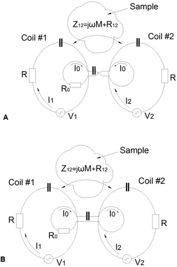
Schematics demonstrating the general ideas of constructing RID circuits using a “butterfly” (“figure eight”) coil (A) a regular surface coil (B). Two geometrically identical resonant coils #1 and #2 are coupled with their shared impedance Z12 and characterized by the inductance L, and the resistance R, In the presence of the sample the mutual impedance Z12 contains both reactive, jωM, and resistive component, R12. RID circuits shown in A) and B) are characterized by the inductance L0 and the resistance R0.
Figure 8.
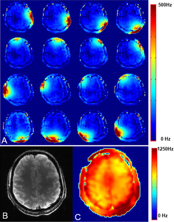
A) Axial B1+ maps for individual surface coil elements. Axial image (B) and corresponding B1+ map (C) obtained using the 16-coil (1×16) overlapped array.
Figure 2.
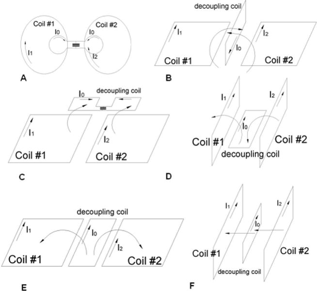
Schematic of various RID circuits.
It is also of importance to evaluate the current I0 flowing in the RID circuit. For example, for the “figure eight” RID from Eqs.[1] and [5] we obtain
| [7] |
In the case of equal current amplitudes (i.e. I1=I2=I) the amplitude of , where ϕ is the phase shift between I1 and I2.
EXPERIMENTAL
To demonstrate these concepts we built several 298 MHz (1H frequency at 7T) 2-coil arrays with resonant (RID) and conventional non-resonant inductive decoupling for comparison. All of these arrays were built using non-overlapped rectangular surface coils of the same size (7.5 cm × 9 cm) with a 13 mm gap between adjacent (Δn=1) coils. Each surface coil was formed from copper tape (6.4 mm width) with six capacitors (100C series, American Technical Ceramics, Huntington Station, NY) uniformly distributed along the coil’s length. All the coils were individually tuned and matched using variable capacitors (Voltronics, Denville, NJ). The RID coils (4 mm ID) were built using 18 gauge copper magnet wire (diameter 1 mm) and positioned at ~ 10 mm distance from the surface coil plane to increase the separation from the sample.
We also built a 16-coil single–row (1×16) array consisting of smaller (5.6 -width and 9 cm - length) overlapped rectangular surface coils (Fig.3). A schematic of an individual surface coil is shown in Fig.4. The surface coils were formed using 5 mm copper tape and overlapped by 12 mm. The coupling between adjacent coils (Δn=1), both reactive and resistive, was compensated by using the RIDs. RID circuits (3 mm ID) were constructed using 20 gauge (diameter 0.8 mm) magnet wire. The proximity of the next nearest surface coils (i.e. Δn=2) resulted in mutual inductive coupling of ~ 5 nH (k ~ 0.03). This coupling was eliminated by the use of conventional non-resonant inductive decoupling (4,9) as shown in Fig.4. For the non-resonant inductive decoupling circuits we used two-turn small (2.3 mm diameter) coils made of 20 gauge magnet wire and wound in opposite directions instead of single loop coils as described previously (4,9). To decrease radiation losses (24) a shield (50 μm polyamide film with a 5 μm copper layer, Sheldahl, Northfield, MN) was placed 4 cm away from the surface coils. To make sure that the RF field produced by RIDs is well localized and does not perturb the B1 of the array within the head we measured transmit B1 maps (phase and amplitude) (25). Then we compared them with the maps obtained with the same arrays but decoupled using conventional non-resonant inductive decoupling, which does not significantly perturb the RF field profile (4,9).
Figure 3.
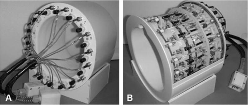
Photographs of the back (A) and the front (B) sides of the 1×16 phased array. Photo on Fig. 3B shown with the top cover removed.
Figure 4.
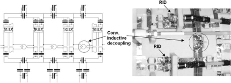
Schematics of the individual surface coils including matching and decoupling networks.
To mimic head loading conditions we constructed two phantoms both filled with NaCl and sucrose in water (26). The percentage by weight measured 41.7%, 56.3% and 2.1% for water, sucrose and NaCl, respectively. The conductivity and the dielectric permittivity measured 0.57 S/m and 52 respectively, which approximates that reported for the human head at 300 MHz (1H resonance frequency at 7 T). The two-coil arrays were evaluated using a 2.0L spherical phantom (16 cm dia.). The 1×16 array was evaluated using a cylindrical phantom with an elliptical cross-section (14 cm × 17 cm). With the described solution this provides loading similar to that of an average sized human head. Coupling coefficients k and k0 were estimated as previously described (27). Q-factors of RIDs were estimated from the frequency dependence of S12 and measured using a weakly coupled pair of pick up coils (28). Q-factors of the surface coils were evaluated using the frequency dependence of S11 (28). For the 1×16 array QU of individual surface coil elements measured 270. QL measured on an average size human head varied from ~ 70 (QU/QL = 3.9) for the posterior coils (closest to the head) up to ~100 (QU/QL = 2.7) for the anterior coils (furthest from the head).
All data were collected using a 7 Tesla Agilent system. To test the coil performance, gradient echo images (256 × 256 × 13 slices) from an adult subject and a phantom were collected using 2/8 mm slice thickness/gap, 19.2 cm × 19.2 cm field of view (FOV), TR = 400 ms, nominal flip angle 15°. B1 maps of the individual coils (single coil transmitting) or the combined array (all coils transmitting simultaneously) were collected using a rapid gradient echo dual angle method (25) with 64 × 64 resolution, TR = 1 s, 5/5 mm slice thickness/gap centered on the matched gradient echo images. All human studies were performed under an IRB (Human Investigations Committee) approved development project.
RESULTS
First, the geometry of the RID circuit was optimized to insure that it did not perturb the profile of RF magnetic field B1 produced by a pair of well decoupled surface coils. First, we evaluated the two RID geometries shown in Figs.2A (21) and 2B (22). We also evaluated the effect of positioning the “figure 8” decoupling coil perpendicular to the plane of the surface coils (Fig.2D) to minimize distortion of the B1 field. Table 1 summarizes data for the 5 different configurations including their size, the coupling coefficient k0, the resonant frequency, and the Q-factor. Figs.5A through 5D show axial maps of the amplitude of the combined simultaneous B1+ for five slices separated by 10 mm located near the surface coil center. The maps were obtained using 2-coil arrays with conventional non resonant inductive decoupling (Fig 5A) and three different sizes (Figs 5B–D) of “flat” RIDs (Fig.2A) and an optimized RID (Fig. 5E) described below. In an attempt to minimize the distortion of the B1 field by the “flat” RID circuit we started with a small coil of 16 mm in diameter (Fig. 5B). As seen from Table 1 the value of f0 was only 5 MHz less than fL (ξ=0.017). Despite the small size of the RID coil the B1 profile of the array was significantly altered at the surface of the sample. To minimize the RF field distortions by increasing ξ while keeping the same RID geometry we increased the RID coil diameter to 22 mm and 28 mm, resulting in in ξ=0.03 (f0 = 289 MHz) and ξ=0.06 (f0 = 280 MHz), respectively. However, this caused similar distortions in the B1 field (Figs. 5C and D). All other types of RIDs presented in Table 1 also produced substantial B1 field distortion.
Table 1.
Parameters of RID circuits.
Figure 5.
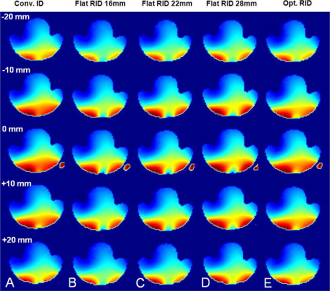
Axial maps of the amplitude of the combined simultaneous B1+ for five slices separated by 10 mm located near the surface coil center. The maps were obtained using 2-coil arrays with conventional non resonant inductive decoupling (A), three different sizes (B–D) of “flat” RIDs (Fig.2A), and the optimized RID (E).
To minimize the B1 field distortion by localizing the RID RF field and at the same time to keep sufficiently large k0 and ξ we constructed optimized RID circuits (Fig.6). The B1 map (Fig 5E) obtained using the 2-coil array with the optimized RID demonstrates minimal distortion and is very similar to that obtained using the array with non-resonant inductive decoupling. The optimized RID circuit consisted of two small two-turn inductors connected in series with the surface coils and an electrically insulated resonant coil with a pair of two-turn loops coupled to each surface coil (Fig.6, Table 2). To match Eq. [2], (i.e. the magnetic fluxes generated by adjacent surface coils produce voltages of opposite sign in the RID loops), all four two-turn loops of the RID circuit should be wound in appropriate directions, i.e. two of the four loops were wound clockwise and two of them counterclockwise (Fig.6). In spite of much smaller size of the optimized RID circuits we obtained substantially larger k0 values (Table 2) as compared to non-optimized RIDs (Table 1).
Figure 6.
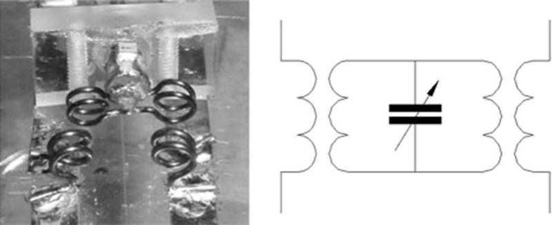
Photograph and schematic of the optimized RID circuit.
Table 2.
Parameters of the optimized RID circuit.
| k0 | Loop size | f0, MHz | ξ | Q0 |
|---|---|---|---|---|
| 0.14 | Dia. 4 mm | 259 | 0.13 | 300 |
Figure 7 shows dependence of the loaded Q-factor, QL, measured for the 2-coil array decoupled using non resonant inductive decoupling, optimized RID, and the 16 mm “flat” RID (Fig.2A) on distance between the phantom and the surface coils. As seen from the figure presence of the not optimized small RID substantially increases QL at distances up to 7 cm, which is much greater the size of the RID circuit itself.
Figure 7.
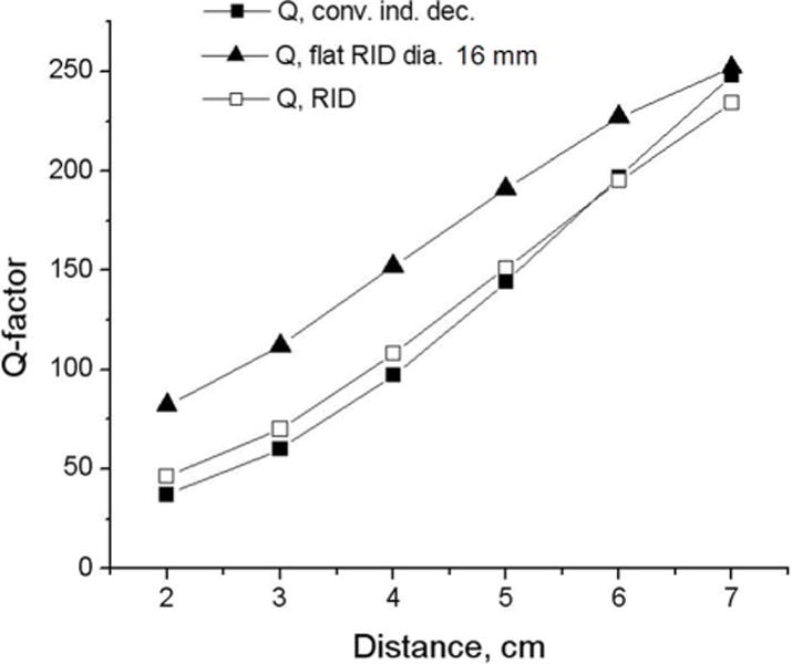
Dependence of the loaded Q-factor, QL, measured for the 2-coil array decoupled using non resonant inductive decoupling, optimized RID, and the 16 mm “flat” RID (Fig.2A) on distance between the phantom and the surface coils.
For the 1×16 array using optimized RID (Fig.6) in combination with overlapping we obtained decoupling better than −24 dB for all adjacent coils. Decoupling of −19 dB or better was obtained for all other surface coils. Figure 8A shows axial B1+ maps for individual surface coil elements demonstrating good decoupling. Figures 8B and C show combined axial image and corresponding B1+ map obtained using the 16-coil (1×16) overlapped array. Homogeneity was evaluated as the standard deviation of the B1+ over the entire slice and measured 9.2 %.
DISCUSSION
In the presence of lossy human tissue the mutual impedance Z12 may include both reactive and resistive components. For example, in the case of overlapping surface coils, which is one of the most common inductive decoupling techniques, the resistive component can reach substantial values (15,18). Conventional capacitive and inductive decoupling methods only compensate for the reactive component of the Z12, and thus do not provide sufficient decoupling of the elements within an array of overlapped of coils. For example, for an overlapped 1×16 array when unloaded, critically overlapped surface coils were well decoupled to the level below −20 dB. However, when loaded with a human head the best decoupling achieved between adjacent surface coils was ~ −11 dB, which corresponds to R12/R ~ 0.3. According to Eq.4 the ratio of the RID-induced reactance to resistance (i.e. imaginary to real changes in the off diagonal elements) is approximately equal to 2Q0ξ. For Q0 of ~200 and the ξ value of ~0.07 (Δf ~ 20 MHz) we obtain the value of ~ 30. Since the induced reactance is equal to the mutual inductance between the surface coils, the RID-induced resistance is ωkL/2Q0ξ. For critically overlapped surface coils (~13.5 mm in our case) the mutual inductance (or k) is close to zero, therefore, the resistive component R12, remains, limiting decoupling to −11dB. Since the RID induces both a reactive and resistive component we induced a small inductive component by reducing the overlap by ~1.5 mm to 12 mm, generating k in the range from 0.02 to 0.025 (mutual inductance M ~ 3 to 4 nH). Using the RID shown in Fig.6 we were then able to compensate (−24 dB coupling) for both the resistive and the reactive (induced by changing overlap) components of the Z12 while minimizing B1 distortion. For the non-adjacent (Δn=2) surface coils where resistive coupling is negligible we used non-resonant inductive decoupling. The QU value of individual surface coils was 270 in comparison to 360 for a single surface coil of the same size. Despite some reduction in QU, we obtained a QU/QL ratio of 2.7 or greater for all coils with the head; including the less loaded anterior surface coils.
Previously we demonstrated, that multiple-channel single-row (1×8) and the double-row (2×8) 7T transceiver phased arrays could be successfully constructed using non-resonant inductive decoupling circuits, consisting of two small, strongly coupled loops each connected in series with the adjacent surface coils (4,9). The decoupling was adjusted mechanically by changing the position of the loops in respect to each other. Mutual inductance strongly depends on surface coil loading determined by the coil-to-sample separation. Since the decoupling is not adjusted on a patient by patient basis, it is crucial to maintain similar loading, e.g. by maintaining a similar distance from each coil to the sample. Proper loading must be also maintained to optimize the coil efficiency and the SNR. The substantial increase in the number of decoupling units for multi-row arrays (e.g. 40 in 2×8 array (8–10)) makes even the one-time mechanical adjustment prior to deployment for experimental use cumbersome. Unlike non-resonant decoupling where the physical separation and/or orientation between the inductive loops have to be adjusted, the RID method provides an easy way to perform the initial adjustment of the decoupling by changing the resonant frequency of the circuit (i.e. adjustment of a single variable capacitor).
When using the RID circuits, their geometry and placement is critical in minimizing the perturbation to the B1 field generated by the individual coils in the array. All attempts to utilize previously described RID geometries (21–23) for decoupling a pair of 7.5 cm × 9 cm surface coils failed. As seen from Fig.5B even a very small 16 mm “flat” RID circuit (21) produces substantial distortions of the B1 field of the array. Importantly, these distortions are seen at distances much greater than the size of the RID circuit itself. For “flat” RID circuits substantial increase in QL (i.e. decrease in loading) in comparison to non-resonant decoupling is observed at distances of up to 7 cm separation between the object and array (Fig.7). When the difference between f0 and fL, Δf, becomes too small even small resonant circuits can produce substantial distortion in the B1 field of the array. To increase the Δf value the coupling between the RID and the surface coils, k0 must be increased. Without substantially modifying the RID geometry k0 can only be increased by increasing the size of the RID loops. Since larger RID loops extend the spatial extent of the distortion, all attempts to minimize it simply by changing the size of the RID circuit failed (Fig.5). Thus the geometry of the RID circuit plays an important role in enabling the size of the RID circuit to be kept small while keeping k0 sufficiently large. Using the optimized RID circuits shown in Fig.6 we were able to simultaneously satisfy both these requirements.
CONCLUSIONS
We have developed and experimentally verified a novel inductive decoupling method using RID coil, which compensates for both reactive and resistive components of the mutual impedance between the adjacent surface coils. After optimizing the geometry of the RID circuit the method provides an easy way of adjusting the decoupling by changing the resonance frequency.
Acknowledgments
Grant sponsor: National Institutes of Health
Grant numbers: R01- EB009871;R01- EB011639; R01NS081772
Abbreviations
- RID
resonant inductive decoupling
- SAR
specific absorption rate
- FOV
field of view
References
- 1.Adriany G, Van de Moortele P-F, Wiesinger F, Moeller S, Strupp JP, Andersen P, Snyder C, Zhang X, Chen W, Pruessmann KP, Boesiger P, Vaughan JT, Uurbil K. Transmit and receive transmission line arrays for 7 Tesla parallel imaging. Magn Reson Med. 2005;53:434–445. doi: 10.1002/mrm.20321. [DOI] [PubMed] [Google Scholar]
- 2.Mao W, Smith MB, Collins CM. Exploring the limits of RF shimming for high-field MRI of the human head. Magn Reson Med. 2006;56(4):918–922. doi: 10.1002/mrm.21013. [DOI] [PMC free article] [PubMed] [Google Scholar]
- 3.Ibrahim TS, Tang L. Insight into RF power requirements and B1 field homogeneity for human MRI via rigorous FDTD approach. J Magn Reson Imag. 2007;25(6):1235–1247. doi: 10.1002/jmri.20919. [DOI] [PubMed] [Google Scholar]
- 4.Avdievich NI, Pan JW, Baehring JM, Spencer DD, Hetherington HP. Short Echo Spectroscopic Imaging of the Human Brain at 7T Using Transceiver Arrays. Magn Res Med. 2009;62:17–25. doi: 10.1002/mrm.21970. [DOI] [PMC free article] [PubMed] [Google Scholar]
- 5.Kozlov M, Turner R. Analysis of RF transmit performance for a multi-row multi-channel MRI loop array at 300 and 400 MHz; Proceedings of the Asia-Pacific Microwave Conference; Melbourne, Australia. 2011; pp. 1190–1193. [Google Scholar]
- 6.Katscher U, Börnert P, Leussler C, van den Brink JS. Transmit SENSE. Magn Reson Med. 2003;49:144–50. doi: 10.1002/mrm.10353. [DOI] [PubMed] [Google Scholar]
- 7.Zhu Y. Parallel excitation with an array of transmit coils. Magn Res Med. 2004;51:775–784. doi: 10.1002/mrm.20011. [DOI] [PubMed] [Google Scholar]
- 8.Zhang Z, Yip CY, Grissom W, Noll DC, Boada FE, Stenger VA. Reduction of transmitter B1 inhomogeneity with transmit SENSE slice-select pulses. Magn Reson Med. 2007;57(5):842–847. doi: 10.1002/mrm.21221. [DOI] [PMC free article] [PubMed] [Google Scholar]
- 9.Avdievich NI. Transceiver phased arrays for human brain studies at 7T. Appl Magn Reson. 2011;41(2):483–506. doi: 10.1007/s00723-011-0280-y. [DOI] [PMC free article] [PubMed] [Google Scholar]
- 10.Gilbert KM, Belliveau J-G, Curtis AT, Gati JS, Klassen LM, Menon RS. A conformal transceive array for 7 T neuroimaging. Magn Reson Med. 2012;67:1487–1496. doi: 10.1002/mrm.23124. [DOI] [PubMed] [Google Scholar]
- 11.Shajan G, Hoffmann J, Scheffler K, Pohmann R. 16-Element dual-row transmitca for 3D RF shimming at 9.4 T; Proceedings of the 20th Annual Meeting ISMRM; Melbourne, Australia. 2012; p. 308. [Google Scholar]
- 12.Adriany G, Auerbach EJ, Snyder CJ, Gözübüyük A, Moeller S, Ritter J, Van de Moortele PF, Vaughan T, Uğurbil K. A 32-channel lattice transmission line array for parallel transmit and receive MRI at 7 Tesla. Magn Reson Med. 2010;63(6):1478–1485. doi: 10.1002/mrm.22413. [DOI] [PMC free article] [PubMed] [Google Scholar]
- 13.Wu B, Wang C, Kelley DAC, Xu D, Vigneron DB, Nelson SJ, Zhang X. Shielded microstrip array for 7T human MR imaging. IEEE Trans Med Imag. 2010;29:179–184. doi: 10.1109/TMI.2009.2033597. [DOI] [PMC free article] [PubMed] [Google Scholar]
- 14.Tropp J. Mutual Inductance in the Bird-Cage Resonator. J Magn Reson. 1997;126:9–17. doi: 10.1006/jmre.1997.1149. [DOI] [PubMed] [Google Scholar]
- 15.Roemer PB, Edelstein WA, Hayes CE, Souza SP, Mueller OM. The NMR phased array. Magn Reson Med. 1990;16:192–225. doi: 10.1002/mrm.1910160203. [DOI] [PubMed] [Google Scholar]
- 16.Kraff O, Bitz AK, Kruszona S, Orzada S, Schaefer LC, Theysohn JM, Maderwald S, Ladd ME, Quick HH. An eight-channel phased array RF coil for spine MR imaging at 7 T. Invest Radiol. 2009;44(11):734–740. doi: 10.1097/RLI.0b013e3181b24ab7. [DOI] [PubMed] [Google Scholar]
- 17.Keil B, Alagappan V, Mareyam A, McNab JA, Fujimoto K, Tountcheva V, Triantafyllou C, Dilks DD, Kanwisher N, Lin W, Grant PE, Wald LL. Size-optimized 32-channel brain arrays for 3 T pediatric imaging. Magn Reson Med. 2011;66:1777–1787. doi: 10.1002/mrm.22961. [DOI] [PMC free article] [PubMed] [Google Scholar]
- 18.Wright SM. Full-wave analysis of planar radiofrequency coils and coil arrays with assumed current distribution. Conc Magn Reson B: Magn Reson Eng. 2002;15(1):2–14. [Google Scholar]
- 19.von Morze C, Tropp J, Banerjee S, Xu D, Karpodinis K, Carvajal L, Hess CP, Mukherjee P, Majumdar S, Vigneron DB. An eight-channel, nonoverlapping phased array coil with capacitive decoupling for parallel MRI at 3 T. Conc Magn Reson B: Magn Reson Eng. 2007;31:37–43. [Google Scholar]
- 20.Avdievich NI, Pan JW, Hetherington HP. Novel inductive decoupling for single- and double-tuned transceiver phased arrays to compensate for both reactive and resistive components of the mutual impedance; Proceedings of the 20th Annual Meeting ISMRM; Melbourne, Australia. 2012; p. 2806. [Google Scholar]
- 21.Aal-Braij R, Peter A, Del Tin L, Korvink JG. A novel inter-resonant coil decoupling technique for parallel imaging; Proceedings of the 17th Annual Meeting ISMRM; Honolulu, USA. 2009; p. 2974. [Google Scholar]
- 22.Soutome Y, Otake Y, Bito Y. Vertical Loop Decoupling Method for Gapped Phased-Array Coils; Proceedings of the 19th Annual Meeting ISMRM; Montreal, Canada. 2011; p. 1859. [Google Scholar]
- 23.Li Y, Xie Z, Pang Y, Vigneron D, Zhang X. ICE decoupling technique for RF coil array designs. Med Phys. 2011;38(7):4086–4093. doi: 10.1118/1.3598112. [DOI] [PMC free article] [PubMed] [Google Scholar]
- 24.Harpen MD. Radiative losses of a birdcage resonator. Magn Reson Med. 1993;29(5):713–716. doi: 10.1002/mrm.1910290522. [DOI] [PubMed] [Google Scholar]
- 25.Pan JW, Twieg DB, Hetherington HP. Quantitative spectroscopic imaging of the human brain. Magn Reson Med. 1998;40:363–369. doi: 10.1002/mrm.1910400305. [DOI] [PubMed] [Google Scholar]
- 26.Beck BL, Jenkins KA, Rocca JR, Fitzsimmons JR. Tissue-equivalent phantoms for high frequencies. Conc Magn Reson B: Magn Reson Eng. 2004;20B(1):30–33. [Google Scholar]
- 27.Picard L, Blackledge M, Decorps M. Improvements in electronic decoupling of transmitter and receiver coils. J Magn Reson B. 1995;106:110–115. [Google Scholar]
- 28.Sucher M, Fox J, editors. Handbook of microwave measurements. New York, London: Willey & Sons, Polytechnic Press of the Polytechnic Institute of Brooklyn; 1963. [Google Scholar]


