Abstract
While the formation of cracks is often stochastic and considered undesirable, controlled fracture would enable rapid and low cost manufacture of micro/nanostructures. Here, we report a propagation-controlled technique to guide fracture of thin films supported on soft substrates to create crack arrays with highly controlled periodicity. Precision crack patterns are obtained by the use of strategically positioned stress-focusing V-notch features under conditions of slow application of strain to a degree where the notch features and intrinsic crack spacing match. This simple but robust approach provides a variety of precisely spaced crack arrays on both flat and curved surfaces. The general principles are applicable to a wide variety of multi-layered materials systems because the method does not require the careful control of defects associated with initiation-controlled approaches. There are also no intrinsic limitations on the area over which such patterning can be performed opening the way for large area micro/nano-manufacturing.
Fracture-induced patterns are ubiquitous in nature, and diverse patterns1,2 are found in many inanimate objects such as dried mud and rocks. Cellular or hierarchical crack patterns are also observed on the surfaces of living creatures, occasionally determining appearances3,4. In order to increase our understanding of these problems, the formation of crack arrays in multilayers has been extensively studied as a fundamental problem in fracture mechanics5,6,7,8,9,10,11. Using this knowledge of the theoretical background, artificial crack patterning on layered materials has been achieved for practical applications in micro/nano-fabrication12,13,14,15,16. Nevertheless, cracks are typically difficult to control precisely as a means of manufacturing, because they tend to initiate from random defects created during processing. Carefully-controlled conditions, such as those that can be obtained in a clean-room, are required to create systems in which any natural defects are small and few enough for fracture to be controlled by the subsequent deliberate introduction of artificial flaws17,18. While it has been shown that such an initiation-controlled approach can be used to control fracture patterns18, this technique has only been applied specifically to materials in which intrinsic flaws are kept below a minimum threshold, and is not robust against accidental introduction of damage or use with soft materials. Here, we report an alternative and more general propagation-controlled approach for precision cracking of multi-layered materials; one that is relatively robust and not sensitive to the nature of the flaws in the system. While our experiments focus on thin films supported by silicone elastomers, the general principles elucidated by the observations are applicable to a broad range of multilayered systems. To our knowledge, this is the first approach to control crack patterns by propagation control, rather than initiation control, and it is a technique that can also be used on multi-layered soft materials, not prepared under clean-room conditions.
Results
Guided fracture of thin films deposited on soft substrates
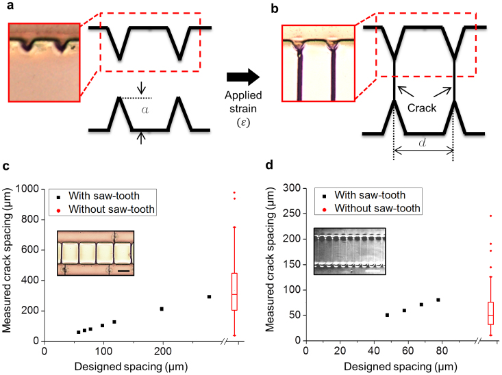
To investigate and demonstrate the concept of guided fracture, we designed parallel microgroove structures with opposing V-notch features, spaced up to 300 μm from each other (forming opposing saw-teeth structures). Polymer-“silica” and polymer-metal bilayer systems were fabricated using micro-patterned polydimethylsiloxane (PDMS) substrates, supporting a thin surface layer of oxidized PDMS (SiOx, 200 nm thick19) or gold (Au, 40 nm on 10 nm chromium (Cr); Fig. 1a). (An adhesion layer of chromium was used to avoid delamination of the fold film during the formation of cracks in this system).
Figure 1. Guiding formation of periodic cracks with saw-tooth structures.
(a,b) Optical images and schematics of multilayer structures fabricated with an array of V-notches, (a) before and (b) after cracks are generated by applied tension. Periodic cracks are produced along V-notches. (c,d) Crack spacing in a (c) Au/PDMS and (d) SiOx/PDMS bilayer system with different saw-tooth spacings as compared to a control measurement without saw-tooth structures at (c) ε ~ 10% and (d) ε ~ 6%. Scale bar: 200 μm.
We determined experimentally that notch lengths of 40 μm were suitable to initiate crack formation in these systems under a minimum applied critical strain (εc) (Fig. 1b). Since the notches are intended to activate existing intrinsic defects at their tips, and shadow defects at other locations, rather than introducing a region of significant stress concentration18, the design of the notch angle was robust over a range of values (see Supplementary Fig. 1s). Notch angles of 50° were chosen for both systems presented in this work, because of the technical difficulties in fabricating an array of very sharp tips using SU-8 photolithography. It was found that an angle of 50° provided the optimum balance of ease-of-fabrication and generation of single cracks. All further experiments were performed using these parameters while varying the spacing, d, between them.
Earlier work has demonstrated that crack arrays are intrinsically much more dense for the SiOx/PDMS system than they are for the Au/PDMS system, owing primarily to the significantly higher modulus of the Au5,13,20 (See Supplementary Information for further discussion of fracture on gold film). In our case, the natural crack spacing with uniform stress applied in the Au/PDMS system was 340 ± 180 μm, and 16.2 ± 8.3 μm in SiOx/PDMS at 10% strain, consistent with analyses21. The spacing of our V-notches fell between these two natural crack spacings, explaining the differences observed between the two material systems studied. For example, the Au/PDMS system at 10% strain produced uniform cracks originating from the notch tips for all the spacings used (50 to 300 μm; Fig. 1c; See Supplementary Fig. 2; Supplementary Table 1s). The SiOx/PDMS system at a lower 6% strain, on the other hand, only formed uniform cracks with spacings ranging from 50 to 80 μm (Fig. 1d; See Supplementary Fig. 3; Supplementary Table 2). At larger spacings and strains, additional cracks were formed between notches (See Supplementary Fig. 4). The high modulus of the gold was also responsible for driving the cracks into the substrate, which also affected the crack spacing5,20. The wrinkles that often formed at higher strains perpendicular to the cracks were generated by a Poisson's ratio effect22. The uncracked region of the substrate induced a compressive strain in the cracked surface layer, where the stresses had been relaxed by the cracks. This compressive transverse strain was relaxed by buckling.
Three regimes of cracking
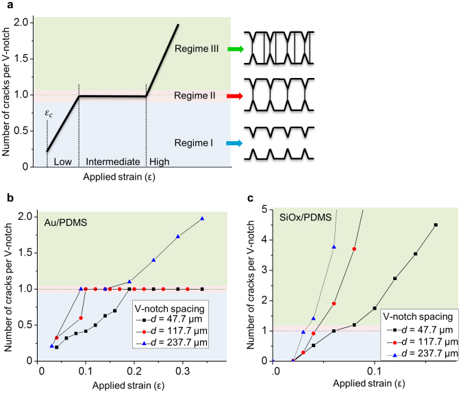
Three regimes of crack formation were identified based on the level of applied strain (Fig. 2a and See Supplementary Fig. 5). In Regime I, at low strains below the threshold required to create uniform crack arrays, the ratio of the number of cracks to the number of V-notches was less than 1. In Regime II, at intermediate strains, there was a 1:1 correspondence between the number of cracks and notches. At higher strains, in Regime III, additional cracks were generated between the notches. It is important to note that before entering Regime III, one crack formed from every notch tip (See Supplementary movie).
Figure 2. Regimes of cracking on thin film/PDMS layers.
(a) Schematic of cracking regimes relating crack positions with V-notch positions. In Regime (I) fewer cracks are observed compared to the number of notches (number of cracks per V-notch spacing is less than 1. In Regime (II), this ratio is equal to 1; and in Regime (III) the ratio is greater than 1. (b, c) Measured number of cracks per unit spacing depends on strain applied to the (b) Au/PDMS layer and (c) SiOx/PDMS layer.
As modeled21, in both Regimes I and III, the average crack spacing is similar to that obtained in systems without patterned notches. In Regime I, the thermo-dynamic spacing is larger than the spacing of the V-notches. In Regime III, the thermo-dynamic spacing is smaller than the spacing of the V-notches, and cracks can be initiated from intrinsic defects between notches. The range of strains over which Regime II can be obtained is dependent on the spacing between the notches, and is dictated by the strains corresponding to the inherent crack spacing that would be obtained in the absence of notches. Therefore, the link between the appropriate strain range and the notch spacing depends on the material properties of the system (Fig. 2b–c). Our experiments showed that a wider notch spacing reduces the strain range for Regime II and, while we were able to obtain a broad range of strains for Regime II in the Au/PDMS system, achieving the same strain range in SiOx/PDMS would have required a much smaller spacing of V-notches.
Optimization of notch structure positioning and strain rates
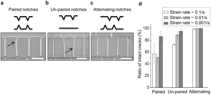
Although uniform crack spacing was achieved in Regime II, individual cracks in paired notches occasionally generated multiple branches. Presumably, cracks simultaneously propagated from opposing sides and met to form misaligned cracks (Fig. 3a). To reduce the incidence of such imperfections, we tested un-paired notch configurations that initiate cracks from one side only. However, cracks starting from the notched side occasionally did not propagate to the other side; and intrinsic defects along the un-patterned side were occasionally activated and extended to the notched side (Fig. 3b). To address these imperfections, alternating notch structures were tested. This configuration significantly improved crack quality, and cracks propagated only from the notches (Fig. 3c). The problem with paired notches is that each notch in a pair will be the same distance from a fully channeled crack. Cracks will be equally likely to propagate from either notch. A similar problem exists with notches on only one side. Since the notches only serve to control crack propagation, and shield flaws at neighboring sites, channel cracks can equally likely grow from the un-notched side as from the notched side. The advantage of the alternating notches is that each notch on each side provides a single site from which it is thermo-dynamically possible for a crack to channel at a given level of strain and current crack pattern.
Figure 3. Optimal conditions for intact crack formation depend on structures of notches and strain rates.
(a) A branched crack formed on samples with paired notch features. (b) A disconnected crack on samples with un-paired notch features. (c) Only single, intact cracks form on samples with alternating notch features. (d) Intact cracks formation increases at lower strain rates ( ~ 0.1/s, 0.01/s, and 0.001/s). Scale bar: 250 μm.
Another fabrication parameter found to be useful for improving crack quality was the strain rate. A reduction in the applied strain rate improved quality of cracks formed particularly for the paired and un-paired notch features (Fig. 3d). This improvement is presumably because slow strain rates give cracks sufficient time to propagate across the specimen surface before fresh cracks were initiated from the opposite face.
Controlled fabrication of arrays with user-defined variable crack spacing
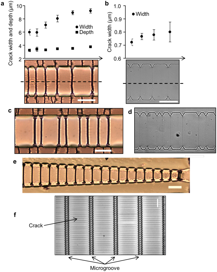
To demonstrate the versatility of this technique beyond uniformly spaced notches, structures with varying notch spacing were designed. Although with limits on the magnitude of notch spacing variability that could be accommodated, it was possible to generate arrays of cracks with variable spacing in both Au/PDMS and SiOx/PDMS systems (Fig. 4a–d). The key is to maintain the applied strain and notch spacing such that the entire system stays within the cracking regime II (Fig. 2a). We did observe, as expected, that for a given strain, crack widths were larger in regions of increased notch spacing (Fig. 4a–b), owing to the larger stress that had to be accommodated by each crack. Rather than have notch features with uniform or gradually increasing spacing, the notch features could also be made to have irregular spacing (Fig. 4c–d). Increasing crack lengths with offset notch positions (Fig. 4e) or aligned notch positions (Fig. 4f) could be generated in Au/PDMS (Fig. 4e) or SiOx/PDMS system (Fig. 4f) to provide crack patterns over large areas. Additionally, arrays of width-adjustable cracks that are each several millimeters in length could also be obtained (See Supplementary Fig. 6a). Millimeter long cracks in the Au/PDMS system were sometimes observed to be branched; however, this was overcome by utilizing sequential arrays of diamond shaped notches which encourage the crack generation in both directions and connected each other without branching (See Supplementary Fig. 6b).
Figure 4. Controlled cracking on flat and curved surfaces.
(a,b): Crack dimensions in (a) Au/PDMS bilayers and (b) SiOx/PDMS bilayers vary depending on V-notch spacing. (c,d) Irregular periodic spacing can also provide precisely generated cracks. (e) Increasing crack lengths structures generated by controlled cracking of an Au/PDMS bilayer. (f) Nanocrack arrays extending several millimeters in lengths and centimeters widths formed on SiOx/PDMS bilayers. Scale bar: 200 μm.
Controlled fracture on curved surfaces
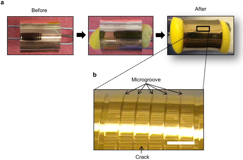
We further utilized these principles to demonstrate fabrication of three dimensional, micro- and nano-sized patterns on multilayer soft polymer systems. (Fig. 5; See Supplementary Fig. 7) Orientation of the crack patterns can be controlled by changing the applied forces. For example, a thin, Au/PDMS film (~1 mm) was rolled and bonded into a cylinder by plasma treatment or a clip. The film was thin enough not to generate cracks during the rolling step. A hoop stress was gradually applied to the cylinder by the slow expansion of a compressed foam cylinder (Fig. 5a). The resultant cracks followed the designed notch pattern (Fig. 5b), demonstrating that this technique is potentially applicable to broader ranges of non-flat pattern fabrication.
Figure 5. Three-dimensional micro- and nano sized patterns on multilayered polymeric system.
(a), microgroove features with V-notches before cracking. (b), patterned cracks on a rolled Au/PDMS sheet. A thin, rolled Au/PDMS sheet was stretched by radial stress resulting from expansion of a compressed foam cylinder. Scale bar: 1 mm.
Discussion
It is important to realize that the situation considered in the current work, and the strategy for forming regular pattern is fundamentally different from that presented by Nam et al. for relatively “defect-free” material systems18. The approach described in that work was one that relied on controlling the flaw population responsible for generating cracks. By careful processing, the intrinsic flaw population was kept so low that, in the absence of artificial flaws, the crack spacing would be much greater than expected from the predictions of fracture mechanics. The introduction of artificial flaws then allowed control of the crack spacing, but always at spacings much larger than the thermo-dynamic equilibrium levels.
The mechanics of fracture can be broadly categorized into two situations: (i) the “defect-free” situation where there are few defects large enough to readily nucleate crack, and (ii) the situation where the number of large defects from which cracks readily propagate is not limiting. In the former situation, the limiting factor to initiate cracking is achieving sufficiently high stress. Thus, in such materials, cracks formation can be controlled by stress concentration without much concern for unintended crack formation. The challenge is creating materials with features that are sharp enough to create the level of stress concentration needed to form crack while maintaining the material devoid of any unintended damage or flaws. This type of defect-free materials requires careful fabrication techniques, often in a clean-room18.
The alternative situation in which crack arrays are propagation controlled is more common. Here, the statistics of the flaw population do not play a significant role in determining the average spacing of arrays, and the spacing is determined primarily by the applied strain, the toughness and thickness of the film and the modulus of the film and substrate5,9,13,23. Thus, in such materials, controlled crack formation relies on the shielding of crack propagation from unwanted sites, rather than actively initiating cracks from artificial flaws. Our current work falls under this latter category, and a detailed analysis of the interaction between the mechanics and the statistics of these two approaches has been presented elsewhere21.
To be more specific, whether intrinsic flaws might trigger random cracks to initiate would depend on the spacing between the V-notch stress concentrators and the intrinsic defect density. In our system, the notch spacing is much larger than the spacing between intrinsic flaws. Conversely, in the system described by Nam et al18. the “natural” crack spacing, which assumes abundant flaws, can be estimated as being about 4 μm, using the data given in that paper18 and the analysis of Thouless et al11. This is much smaller than the notch spacing of 100 μm that was used in that study, and the fact that the notches resulted in a crack spacing much larger than the natural spacing indicates that a very low density of intrinsic flaws was achieved by the careful processing. The systems we present in this paper are much closer to an equilibrium configuration. Therefore, the fabrication of uniform crack arrays requires not only creation of stress-concentrating features, but coordination of spacing between the features with the applied strain. The beneficial consequence of this design approach is that the crack patterns are stable against the introduction of additional flaws making it more robust and applicable to a broader range of materials and processing parameters including curved and 3D soft structures.
In summary, we demonstrate robust guidance of fracture in multilayer soft materials via selective activation of intrinsic defects based on matching spacing design and strain application with material properties of the system. In defect-rich materials such as utilized in this paper, precision fracture fabrication requires undesired stress suppression first, then localized stress focusing to initiate cracks second. Here, we balance these two opposing requirements of stress relief and focusing using alternating V-notch features, slow strain rates, and most critically the use of a strain where the V-notch spacing matches the equilibrium average crack spacing of the material system under study. This simple and versatile approach achieves surprisingly precise micro- and nanoscale features in a variety of readily-processed materials and in a variety of geometries including curved surfaces.
Methods
Saw-tooth structure design and device fabrication
V-notch structures were fabricated using standard soft lithographic techniques. Patterns were designed in AutoCAD, and printed on transparent films (CAD Art inc.). SU-8 lithography was used to prepare a mold on silicon wafers. A 5:1 mixture of curing agent and PDMS (Sylard 184, Dow Corning) was mixed and cast against the molds, and were cured at 60°C for at least 4 hours, before peeling the finished structures from the mold. Two different thin film layers were produced on the cured PDMS: i) plasma treated oxidized PDMS layer: the cured PDMS having the transferred microstructures were directly exposed to plasma treatment for 6 min at 200 W (COVANCE-MP, Femto-science inc.); ii) cured PDMS was coated with 10 nm of Cr layer first as a adhesion layer and then 40 nm of Au layer using e-beam deposition. A tensile strain was applied using specially designed stretchers.
Microscopy and image analysis
The bright field images were acquired using a Nikon Ti-U microscope. Laser interferometer (LEXT, Olympus OLS4000) at 100x magnification was used to observe 3D images of cracks. The LEXT software was used to measure width, spacing, and depth of the cracks.
Strain rate dependent crack formation
Defined strain rate stretching was performed using a programmed, electric stepping motor driven stretcher (Scholar Tec Corp., Osaka, Japan. Model: NS-500; a similar system is available from Strex ST-140). This system was used to compare crack formation between paired, un-paired, and alternating V-notch structures. Crack images were taken by an inverted microscope.
Author Contributions
B.C.K. and T.M. developed saw-tooth induced cracking. B.C.K. fabricated the thin film/soft substrate devices, and collected analysed data. C.M., B.C.K. and J.H. conducted numerical simulations of the stress concentration on the V-notch structure. M.D.T. guided the understanding of the mechanics issues. S.T. was responsible for the overall design and direction of the project. B.C.K., C.M. and M.D.T. wrote the manuscript. All authors contributed to the design and interpretation of the experiments, and edited the manuscript.
Supplementary Material
Supplementary information
Crack generation
Acknowledgments
We thank Prof. Mark Burns and Jae-Sung Lee for metal deposition. We also thank Prof. Keiji Naruse for the electronic stretching system and Wei-Tang Wang for doing some initial preparatory studies. This work was supported by a grant from the US National Institutes of Health (HG004653-03).
Reprints and permissions information is available at http://www.nature.com/reprints
References
- Federl P. & Prusinkiewicz P. A texture model for cracked surfaces, with an application to tree bark. Proceedings of Western Computer Graphics Symposium. 23–29 (1996). [Google Scholar]
- Leung K.-T., Jozsa L., Ravasz M. & Neda Z. Pattern formation: Spiral cracks without twisting. Nature 410, 166–166 (2001). [DOI] [PubMed] [Google Scholar]
- Ball P. Shapes: Nature's patterns: A tapestry in three parts. Vol. 1 (Oxford University Press, 2011). [Google Scholar]
- Milinkovitch M. C. et al. Crocodile Head Scales Are Not Developmental Units But Emerge from Physical Cracking. Science 339, 78–81 (2013). [DOI] [PubMed] [Google Scholar]
- Thouless M. D., Li Z., Douville N. & Takayama S. Periodic cracking of films supported on compliant substrates. J.Mech. Phys Solids (2011). [DOI] [PMC free article] [PubMed] [Google Scholar]
- Ye T., Suo Z. & Evans A. G. Thin film cracking and the roles of substrate and interface. Int. J. Solids Structures 29, 2639–2648 (1992). [Google Scholar]
- Beuth J. Cracking of thin bonded films in residual tension. Int. J. Solids Struct 29, 1657–1675 (1992). [Google Scholar]
- Hutchinson J. W. & Suo Z. Mixed mode cracking in layered materials. Adv. Appl. Mech 29, 191 (1992). [Google Scholar]
- Shenoy V., Schwartzman A. & Freund L. B. Crack patterns in brittle thin films. Int. J. Fracture 103, 1–17 (2000). [Google Scholar]
- Thouless M. D. Crack spacing in brittle films on elastic substrates. J. Am. Ceram. Soc 73, 2144–2146 (1990). [Google Scholar]
- Thouless M. D., Olsson E. & Gupta A. Cracking of brittle films on elastic substrates. Acta. Metall. Mater 40, 1287–1292 (1992). [Google Scholar]
- Huh D. et al. Tuneable elastomeric nanochannels for nanofluidic manipulation. Nat. Mater. 6, 424–428 (2007). [DOI] [PubMed] [Google Scholar]
- Mills K. L., Huh D., Takayama S. & Thouless M. D. Instantaneous fabrication of arrays of normally closed, adjustable, and reversible nanochannels by tunnel cracking. Lab Chip 10, 1627–1630 (2010). [DOI] [PubMed] [Google Scholar]
- Zhu X. et al. Fabrication of reconfigurable protein matrices by cracking. Nat. Mater. 4, 403–406 (2005). [DOI] [PubMed] [Google Scholar]
- Matsuoka T. et al. Nanoscale squeezing in elastomeric nanochannels for single chromatin linearization. Nano letters (2012). [DOI] [PMC free article] [PubMed] [Google Scholar]
- Adelung R. et al. Strain-controlled growth of nanowires within thin-film cracks. Nat Mater. 3, 375–379 (2004). [DOI] [PubMed] [Google Scholar]
- Meitl M. A. et al. Stress focusing for controlled fracture in microelectromechanical systems. Appl. Phys Lett. 90, 083110-083110-083113 (2007). [Google Scholar]
- Nam K. H., Park I. H. & Ko S. H. Patterning by controlled cracking. Nature 485, 221–224 (2012). [DOI] [PubMed] [Google Scholar]
- Mills K. L., Zhu X., Lee D., Takayama S. & Thouless M. D. Properties of the surface-modified layer of plasma-oxidized poly (dimethylsiloxane). Mater. Res. Soc. Symp. Proc. 924, 0924–Z0907 (2006). [Google Scholar]
- Douville N. J., Li Z., Takayama S. & Thouless M. D. Fracture of metal coated elastomers. Soft Matter 7, 6493–6500 (2011). [Google Scholar]
- Jiexi Huang BC. K., Takayama & Thouless M. D. The Control of Crack Arrays in Thin Films. J. Mater. Sci (published online) (2013);. 10.1007/s10853-013-7700-3. [DOI] [PMC free article] [PubMed] [Google Scholar]
- Efimenko K. et al. Nested self-similar wrinkling patterns in skins. Nat. Mater. 4, 293–297 (2005). [DOI] [PubMed] [Google Scholar]
- Dundurs J. Discussion:“Edge-Bonded Dissimilar Orthogonal Elastic Wedges Under Normal and Shear Loading” (Bogy, D. B, 1968, ASME J. Appl. Mech., 35, pp. 460–466). J. Appl. Mech. 36, 650 (1969). [Google Scholar]
Associated Data
This section collects any data citations, data availability statements, or supplementary materials included in this article.
Supplementary Materials
Supplementary information
Crack generation


