Summary
Perforator infarction represents a critical problem after intracranial Wingspan stent. To explore the mechanism of perforator infarction, we simulated the stent-artery interaction at an atheromatous plaque with perforator. Structural deformation and biomechanical stress distribution after stenting were analyzed. High radial stress values were located along the stent struts, which surrounded the area with high circumferential stress. Stretched perforator orifice in a circumferential direction after stenting was simulated. These results show that structural deformation could play a role in the mechanism of perforator occlusion after Wingspan stenting.
Key words: intracranial atherosclerotic stenosis, intracranial stent, fine element method, perforator
Introduction
Intracranial atherosclerosis is a frequent cause of ischemic stroke. A recurrent stroke risk in the same territory was 12-14% in a year despite medical therapy 1,2. Although a self expandable nitinol stent (Wingspan stent system, Stryker, Fremont, CA, USA) achieved high technical success, only one randomized controlled trial, the Stenting and Aggressive Medical Management for Preventing Recurrent stroke in Intracranial Stenosis (SAMMPRIS) trial showed that aggressive medical treatment is superior to percutaneous transluminal angioplasty and stenting with the Wingspan stent 2. The subgroup analysis in the SAMMPRIS study presented infarction involving the perforator territories as the majority (71.4%) of ischemic events 3.
A build up of atheromatous plaque in a parent artery has been reported as an independent predictor for the branch occlusion after stenting 4,5. The mechanism of branch occlusion has mainly been demonstrated by plaque shift after stenting, so-called ‘snow plow effect' 4. However, the SAMMPRIS trial showed no patient with a recent perforator stroke had new perforator territory infarction after Wingspan stent, even though 21% patients qualified with perforator strokes in this trial 3. There can be a mechanism to describe the perforator occlusion other than plaque shift.
Simulated biomechanical stress based on the finite element method has demonstrated the stent-artery interaction 6,7. The simulation analysis in the atherosclerotic model with a perforator has not been reported. This study aimed to explore the mechanism of perforator occlusion after Wingspan stenting, using a finite element method based on an eccentric atherosclerotic model with a perforator.
Material and Methods
FEM simulations
Three-dimensional (3D) computational geometry of the Wingspan stent was created using the package software of Solid Edge (SIEMENS PLM Software, Germany) based on microscopic measurement by an ASONE stereo microscope (ASONE Corporation, Tokyo, Japan); stent diameter and length were 3.5 and 4.2 mm, respectively. The stent strut was 0.07 mm in both width and thickness. The stenotic artery was modeled as a cylinder having a length of 12 mm, an internal diameter of 3 mm and a thickness of 0.3 mm. The minimum diameter of the vascular lumen was 1.5 mm in the middle. The plaque covered a length of 6 mm, and had a thickness accounting for up to 75% of the cross-sectional area in the host vessel 3. The position of the perforator was placed at mid-section of the arterial model to its axial direction; the diameter, length, and thickness of the perforator were 0.4, 5, and 0.04 mm, respectively 8.
In this study, the stress-strain data for the stent material properties were based on those of Nitinol alloy composed of Ti-55.9 wt% 9. The artery and stenosis model was assumed to be a hyperelastic, isotropic, incompressible material. The five-parameter Mooney–Rivlin model was used to describe the material properties of both computational models 10.
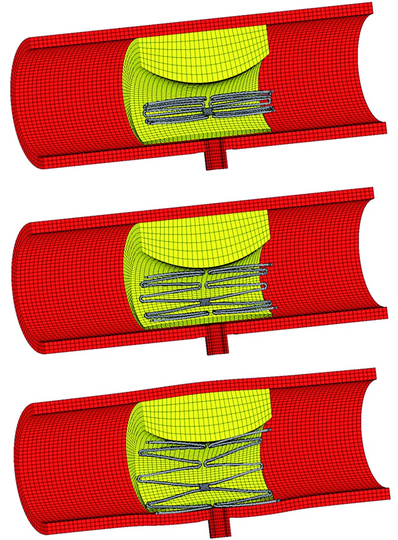
For FEM simulation of the stent–artery interaction, the catheter was modeled as a rigid body defined by a cylindrical surface with a length of 15 mm and outer diameter of 4.5 mm. In the first step, the arterial wall elements were deactivated, and the catheter was shrunk in the radial direction of the cylinder (Figure 1). During this procedure, the stent was gradually crimped to a 1 mm outer diameter. In the second step, the elements of the arterial wall were activated, and the catheter was re-enlarged to release the stent models until they contacted the arterial model. The friction of the stent with the catheter and the contact between the stent and arterial model were treated with a friction coefficient of 0.05 11.
Figure 1.
Illustrations of the analysis procedure for virtual stent placement at an asymmetrical atherosclerosis model with perforator.
During the analysis, the boundary conditions of the stent were constrained in the longitudinal and circumferential directions at three nodes at the medial cross-section. To avoid rigid movement of the artery, fixed displacement boundary conditions were applied to both ends. A grid sensitivity analysis of the arterial model was conducted, and comparisons were performed between the Von Mises stresses at the end of the analysis of three different mesh sizes from 46,000 to 138,000 elements. The percentage difference in the stresses between the finest and selected meshes was 3.4%.
Results
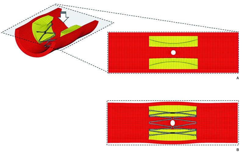
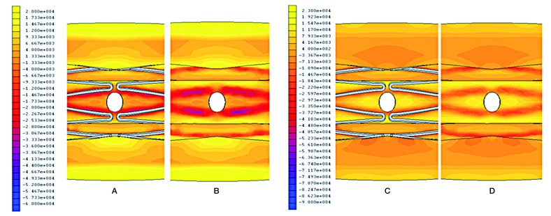
Structural deformation was demonstrated in this model (Figure 2). The cross-sectional area of the vessel lumen increased by 34% in the central part after stenting (pre-procedure; 2.53 mm2, post-procedure; 3.39 mm2). The perforator orifice lost a physiological round stretched in a circumferential direction and formed an oval shape (circumferential diameter; 0.49 mm, axial diameter; 0.39 mm). Figure 3 shows the biomechanical stress distribution around the perforator after Wingspan stenting. A high radial stress (RS) value corresponded with stent struts, and surrounded the area with high circumferential stress (CS). The peak RS value of 96 kPa was located at the apex of stent struts. The perforator orifice positioned between stent struts showed a high CS. The peak of CS value of 23 kPa was positioned at the end points of the minor axis in the perforator orifice.
Figure 2.
Structural deformation of the perforator orifice. Stretched orifices after Wingspan stenting were simulated. Pre (A) and Post-procedure (B).
Figure 3.
Biomechanical stress distribution around a perforator after Wingspan stenting. Radial stress with stent (A), and without stent (B). Circumferential stress with stent (C), and without stent (D).
Discussion
In this study, the biomechanical stress distributions in an atherosclerotic model were simulated with structural deformation. Atheromatous plaque frequently develops at the outer walls of the arterial branches and curvatures, where the local flow is disturbed, causing low or oscillatory shear stress 12. As for a middle cerebral artery, asymmetric plaque was predominantly detected on the ventral and inferior walls opposite the perforator orifice 13. Consequently, our analysis showed the characteristic stent-artery interaction. In particular, the orifice of the perforator was stretched in a circumferential direction after stenting, corresponding to the area with high CS values. The CS has been reported to peak between the stent struts, and be proportional to the gradient of environmental RS values 7,14. Increased RS values could enhance the stretching effect with high CS.
The stretched branch orifice and branch occlusion was observed after stenting in a mild atherosclerotic lesion with 25% stenosis 15. An elongated orifice can disturb the physiological hemodynamics, leading to the thrombus formation and reduced blood flow. Even a modest elliptical change like our result can vary the wall shear stress around the circumference of a cerebral artery 16. In particular, an atherosclerotic perforator with impaired blood flow may readily cause complete ischemic infarction after stenting. The high balloon-artery ratio was reported to be associated with the branch occlusion 17. A balloon-expandable stent, which could add more stress on the arterial wall, could lead to perforator occlusion more often than a self-expandable stent 18. Stretching effect with excessive stress concentration may explain the mechanism of perforator occlusion after Wingspan stenting.
Plaque shift over the orifice was not observed in this asymmetric plaque model. If there is a plaque around the perforator orifice in clinical practice, pre-ballooning or stenting can evoke the plaque shift or rupture, leading to perforator occlusion. Microembolism after plaque rupture is also a possible cause of perforator occlusion. Furthermore, stent strut over the orifice can obstruct the flow into the perforator or form a thrombus. Metal coverage and endothelization of stent struts have been postulated 19. However, lower metal coverage of the Wingspan stent, compared to a flow-diverting stent, is unlikely to occlude the branch 20.
Conclusions
We presented the simulated biomechanical responses with structural deformation elicited by the Wingspan stent, using an eccentric atheromatous plaque model. A stretched perforator orifice was observed in a circumferential direction.
In addition to plaque shift or microembolism, the structural deformation at the perforator orifice may contribute to perforator occlusion after stenting. Perforator infarction in an animal model has not been established and is of limited effectiveness. These insights on structural analysis can help to find solutions to prevent perforator infarction in clinics.
References
- 1.Chimowitz MI, Lynn MJ, Howlett-Smith HJ, et al. Comparison of warfarin and aspirin for symptomatic intracranial arterial stenosis. N Engl J Med. 2005;352(13):1305–1316. doi: 10.1056/NEJMoa043033. [DOI] [PubMed] [Google Scholar]
- 2.Chimowitz MI, Lynn MJ, Derdeyn CP, et al. Stenting versus aggressive medical therapy for intracranial arterial stenosis. N Engl J Med. 2011;365(11):993–1003. doi: 10.1056/NEJMoa1105335. [DOI] [PMC free article] [PubMed] [Google Scholar]
- 3.Fiorella D, Derdeyn CP, Lynn MJ, et al. Detailed analysis of periprocedural strokes in patients undergoing intracranial stenting in Stenting and Aggressive Medical Management for Preventing Recurrent Stroke in Intracranial Stenosis (SAMMPRIS) Stroke. 2012;43(10):2682–2688. doi: 10.1161/STROKEAHA.112.661173. [DOI] [PMC free article] [PubMed] [Google Scholar]
- 4.Aliabadi D, Tilli FV, Bowers TR, et al. Incidence and angiographic predictors of side branch occlusion following high-pressure intracoronary stenting. Am J Cardiol. 1997;80(8):994–997. doi: 10.1016/s0002-9149(97)00591-2. [DOI] [PubMed] [Google Scholar]
- 5.Jiang WJ, Srivastava T, Gao F, et al. Perforator stroke after elective stenting of symptomatic intracranial stenosis. Neurology. 2006;66(12):1868–1872. doi: 10.1212/01.wnl.0000219744.06992.bb. [DOI] [PubMed] [Google Scholar]
- 6.Chen HY, Sinha AK, Choy JS, et al. Mis-sizing of stent promotes intimal hyperplasia: impact of endothelial shear and intramural stress. Am J Physiol Heart Circ Physiol. 2011;301(6):H2254–2263. doi: 10.1152/ajpheart.00240.2011. [DOI] [PMC free article] [PubMed] [Google Scholar]
- 7.Fujimoto M, Shobayashi Y, Tateshima S, et al. Biomechanical responses after Wingspan Stent deployment in swine ascending pharyngeal artery. Neurol Res. 2013;35(1):90–94. doi: 10.1179/1743132812Y.0000000119. [DOI] [PubMed] [Google Scholar]
- 8.Marinkovic S, Gibo H, Milisavljevic M, et al. Anatomic and clinical correlations of the lenticulostriate arteries. Clin Anat. 2001;14(3):190–195. doi: 10.1002/ca.1032. [DOI] [PubMed] [Google Scholar]
- 9.Gong XY, Pelton AR. Finite element analysis on nitinol medical applications. International Mechanical Engineering Congress and Exposition. 2002;53:1–2. [Google Scholar]
- 10.Creane A, Maher E, Sultan S, et al. Finite element modelling of diseased carotid bifurcations generated from in vivo computerised tomographic angiography. Comput Biol Med. 2010;40(4):419–429. doi: 10.1016/j.compbiomed.2010.02.006. [DOI] [PubMed] [Google Scholar]
- 11.Auricchio F, Conti M, De Beule M, et al. Carotid artery stenting simulation: from patient-specific images to finite element analysis. Med Eng Phys. 2011;33(3):281–289. doi: 10.1016/j.medengphy.2010.10.011. [DOI] [PubMed] [Google Scholar]
- 12.Nigro P, Abe J, Berk BC. Flow shear stress and atherosclerosis: a matter of site specificity. Antioxid Redox Signal. 2011;15(5):1405–1414. doi: 10.1089/ars.2010.3679. [DOI] [PMC free article] [PubMed] [Google Scholar]
- 13.Xu WH, Li ML, Gao S, et al. Plaque distribution of stenotic middle cerebral artery and its clinical relevance. Stroke. 2011;42(10):2957–2959. doi: 10.1161/STROKEAHA.111.618132. [DOI] [PubMed] [Google Scholar]
- 14.Capelli C, Gervaso F, Petrini L, et al. Assessment of tissue prolapse after balloon-expandable stenting: influence of stent cell geometry. Med Eng Phys. 2009;31(4):441–447. doi: 10.1016/j.medengphy.2008.11.002. [DOI] [PubMed] [Google Scholar]
- 15.Masuo O, Terada T, Walker G, et al. Patency of perforating arteries after stent placement? A study using an in vivo experimental atherosclerosis-induced model. Am J Neuroradiol. 2005;26(3):543–548. [PMC free article] [PubMed] [Google Scholar]
- 16.Steelman SM, Wu Q, Wagner HP, et al. Perivascular tethering modulates the geometry and biomechanics of cerebral arterioles. J Biomech. 2010;43(14):2717–2721. doi: 10.1016/j.jbiomech.2010.06.024. [DOI] [PMC free article] [PubMed] [Google Scholar]
- 17.Poerner TC, Kralev S, Voelker W, et al. Natural history of small and medium-sized side branches after coronary stent implantation. Am Heart J. 2002;143(4):627–635. doi: 10.1067/mhj.2002.120411. [DOI] [PubMed] [Google Scholar]
- 18.Kurre W, Brassel F, Bruning R, et al. Complication rates using balloon-expandable and self-expanding stents for the treatment of intracranial atherosclerotic stenoses: analysis of the INTRASTENT multicentric registry. Neuroradiology. 2012;54(1):43–50. doi: 10.1007/s00234-010-0826-y. [DOI] [PubMed] [Google Scholar]
- 19.Hong B, Wang K, Huang Q, et al. Effects of metal coverage rate of flow diversion device on neointimal growth at side branch ostium and stented artery: an animal experiment in rabbit abdominal aorta. Neuroradiology. 2012;54(8):849–855. doi: 10.1007/s00234-011-0984-6. [DOI] [PubMed] [Google Scholar]
- 20.De Bock S, Iannaccone F, De Santis G, et al. Our capricious vessels: The influence of stent design and vessel geometry on the mechanics of intracranial aneurysm stent deployment. J Biomech. 2012;45(8):1353–1359. doi: 10.1016/j.jbiomech.2012.03.012. [DOI] [PubMed] [Google Scholar]


