

Abstract

Activation, ex vivo expansion of T cells, differentiation into a regulatory subset, and its phenotype-specific high-throughput selection represent major challenges in immunobiology. In part, this is due to the lack of technical means to synthesize suitable 3D extracellular systems to imitate ex vivo the cellular interactions between T cells and antigen-presenting cells (APCs). In this study, we synthesized a new type of gold-linked surfactant and used a drop-based microfluidic device to develop and characterize novel nanostructured and specifically biofunctionalized droplets of water-in-oil emulsions as 3D APC analogues. Combining flexible biofunctionalization with the pliable physical properties of the nanostructured droplets provided this system with superior properties in comparison with previously reported synthetic APC analogues.
Interactions of T cells and antigen-presenting cells (APCs) play a crucial role in orchestrating the body’s adaptive immune and inflammatory responses to pathogens and mutations. The fate of T cells is exquisitely regulated not only by the presence of certain molecules on the surface of APCs but also by their density and spatial distribution on the nanometric scale.1−6 Moreover, properties such as the elasticity and curvature of both T cells and APCs, in addition to the force-dependent conformational changes during the formation of the immunological synapse (IS) (i.e., the T cell–APC interface), may play a crucial role in the regulation of T cells’ fate.7−12 Recent preclinical studies have indicated that adoptive transfer of regulatory T cells can exhibit a marked beneficial impact on different autoimmune diseases.13−15 Therefore, the induction and ex vivo expansion of T cells in general represents a major challenge because of the difficulty of simulating in vitro the intimate cellular interactions between T-cell receptors (TCRs) and the target APCs as they occur in peripheral lymphoid organs.5 In part, this difficulty is associated with the lack of technical means to develop suitable two-dimensional (2D) and especially three-dimensional (3D) artificial APC analogues.
During the past decade, much effort has been concentrated on the development of 2D APC analogues. The most common technology is based on supported lipid bilayers, which can provide a model system for mimicking the cell membrane because the lateral mobilities of lipids and proteins qualitatively resemble the situation in vivo. Moreover, many surface-patterning techniques have been used to define certain spatial constraints within a lipid bilayer to alter the mobile fraction of functionalized proteins.16−18 However, only a few techniques, such as dip-pen nanolithography,19 e-beam lithography,20 and block copolymer micelle nanolithography (BCML),21 can be used to make patterns with sub-100 nm spatial resolution, a length scale that plays a significant role in T-cell activation.4 Despite the versatility of these systems, only partial success in mimicking the T cell–APC interaction as it occurs in vivo has been achieved.7,22 The ability of these systems to serve as optimal APC analogues is mainly hindered by the lack of mechanosensing capabilities during formation of the IS due to the rigid materials and planar system structure.7,23,24
Monodisperse 5–6 μm diameter polystyrene beads endowed with antibodies or other proteins were heralded as another type of synthetic APCs that was considered to imitate the cellular interactions between T cells and APCs more closely than planar systems can.25 However, the limitation of bead-based artificial APCs is the incompatibility of the system toward dynamic remodeling of the proteins that is established at the IS between actual APCs and T cells.
Drops of water-in-fluorocarbon emulsions created in a drop-based microfluidic device have been tested and used recently as 3D scaffolds for in vitro translation, encapsulation, and incubation of cells.26−30 Nonionic fluorosurfactants made of perfluorinated polyethers (PFPEs) (hydrophobic tails) provide long-term stability to the drops by preventing coalescence, while poly(ethylene glycol) (PEG) moieties (hydrophilic headgroups) serve as a biocompatible, inert interior surface of the water drops.26 The flexible design of the microfluidic device allows for the creation of drops with easily varied diameters ranging upward from 10 μm, the minimum diameter required for single-cell encapsulation.31 The softness of the droplet walls can be efficiently controlled by varying the surfactant concentration prior to droplet formation. Therefore, the change in droplet diameter and consequent change in the curvature, together with the soft nature of this system, increase its potential to confer the key physical functions of native APCs. However, current state-of-the-art emulsion systems fail to provide the required chemical and biological functions of APCs.
In the present study, we developed a novel approach that merges nanopatterning and droplet microfluidics to develop a 3D APC analogue with a well-defined chemical and physical microenvironment. This important challenge was addressed in this study by developing and characterizing novel gold-nanostructured and specifically biofunctionalized drops of water-in-oil emulsions, as illustrated schematically in Figure 1A. Gold nanoparticles (NPs) were used in this study as anchoring points for bioactive molecules, which are required for cell interactions. Additionally, these NPs allowed for qualitative and quantitative characterization of the droplets with high-resolution cryogenic scanning electron microscopy (cryo-SEM).
Figure 1.

(A) Schematic representation of a nanostructured and specifically biofunctionalized drop of a water-in-oil emulsion as a 3D APC analogue. Two T cells encapsulated inside the drop are shown schematically. This schematic representation is not to scale. (B, C) Structures of the PFPE–PEG–PFPE triblock copolymers and PFPE–PEG–Gold diblock surfactants, respectively.
The synthesis of the PFPE–PEG–PFPE triblock copolymer surfactants (Figure 1B) followed the procedure reported earlier26 but with several modifications, such as using a one-step condensation reaction between PEG600-diol and PFPE2500-carboxylic acid [see section 1.1 in the Supporting Information (SI)]. PFPE–PEG–Gold diblock surfactants (30 μM) (Figure 1C) were synthesized using a one-step condensation reaction between PFPE7000-carboxylic acid and (11-mercaptoundecyl)tetra(ethylene glycol)-functionalized gold NPs (see SI section 1.2). Nuclear magnetic resonance (NMR) and Fourier transform infrared (FTIR) spectroscopies were used to confirm the success of the surfactants’ syntheses and their purities (see SI sections 1.1 and 4.1, respectively).
A droplet-based microfluidic device made of polydimethylsiloxane (PDMS) was used to create the water-in-oil emulsion droplets (see SI section 2). Triblock PFPE–PEG–PFPE and diblock PFPE–PEG–Gold surfactants were mixed at different concentration ratios to get stable emulsion droplets with various gold NP densities. To verify the successful creation of the nanostructured droplets, the droplets were freeze-fractured and investigated by cryo-SEM (see SI section 4.2). Figure 2 shows representative top-view cryo-SEM micrographs of freeze-fractured nanostructured droplets created using different concentrations of the gold-linked surfactant [(A, B) 30 μM; (C, D) 3 μM]. The ∼5 nm diameter gold NPs are located on the inner periphery of the droplets, with a higher density and more homogeneous distribution on the droplets obtained using a higher concentration of gold-linked surfactant (30 μM) (Figure 2B). To prove that the bright dots were gold NPs and not artifacts due to the cryo-SEM measurements or freeze-fracture preparation, droplets without gold-linked surfactants were created, freeze-fractured, and observed by cryo-SEM (see SI section 4.2 and Figure 10S).
Figure 2.
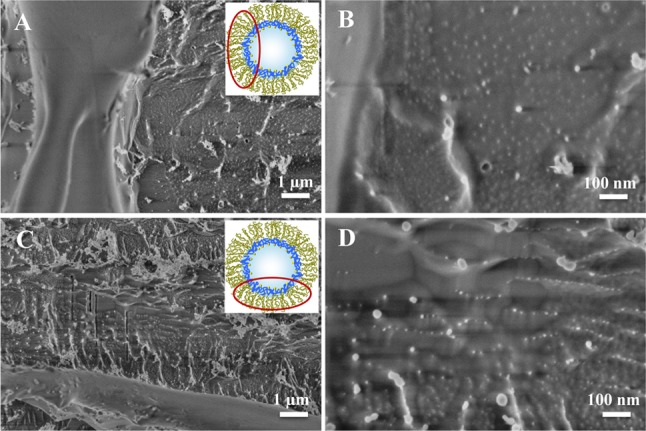
Representative cryo-SEM micrographs of freeze-fractured nanostructured droplets obtained with different magnifications. The droplets were created using a PFPE–PEG–PFPE triblock copolymer surfactant concentration of 20 mM and PFPE–PEG–Gold surfactant concentrations of (A, B) 30 μM and (C, D) 3 μM. For clarity, the insets show schematic representations of the droplet and the area of observation (not to scale).
The ability of the gold NPs in the nanostructured droplets to serve as anchoring points for future biofunctionalization was tested with two different approaches. The first approach was based on functionalization of the created nanostructured droplets with His6-tagged green fluorescent protein (His6-GFP) via a nitrilotriacetic acid (NTA)-thiol linker (see SI sections 1.4 and 4.3.1). Successful functionalization of the nanostructured droplets with His6-GFP is particularly important because the chemistry behind the immobilization of these proteins is the same as that required for immobilization of peptide-loaded major histocompatibility complexes (pMHCs) or proteins such as aCD3 or aCD28, which are important in T-cell activation.32 The second approach involved two steps: synthesis of PFPE–PEG–Gold surfactants linked to rhodamine B (RhB) (see SI section 1.3) followed by creation of RhB-linked nanostructured droplets (see SI section 4.3.2).
For the first approach, a freshly prepared phosphate-buffered saline (PBS) solution of His6-GFP–Ni-NTA-thiol (8 μM) was used as the aqueous phase to create droplets in the microfluidic device. Two types of droplets were investigated, one type containing only PFPE–PEG–PFPE (20 mM) in the oil phase and the other containing a mixture of PFPE–PEG–PFPE (20 mM) and PFPE–PEG–Gold (30 μM) in the oil phase. Figure 3A–C shows fluorescence images of the His6-GFP–Ni-NTA-linked nanostructured droplets taken 1, 4, and 10 days after their creation, respectively. It can be seen that the fluorescence is concentrated on the periphery of the droplets. The decrease in the fluorescence intensity after 4 days can be explained by dilution of the GFP in the periphery of the droplets due to oxidation of the gold–sulfur bond in the aqueous phase33 and subsequent diffusion to the oil phase. In the oil phase, GFP loses its fluorescent properties because of solvent-induced denaturation.34 In comparison to nanostructured droplets, the fluorescence intensity in droplets without gold NPs was distributed uniformly inside the droplets (see Figure 11S, panel A). The same uniform distribution was observed in nanostructured droplets where His6-GFP (8 μM) was used without the NTA-thiol linker (see Figure 11S, panel B).
Figure 3.
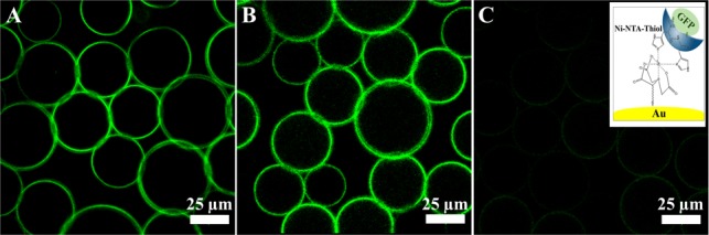
Representative fluorescence images of the GFP-linked gold-nanostructured droplets, measured (A) 1 day, (B) 4 days, and (C) 10 days after their creation. All of the images have the same intensity scale. The right inset schematically shows the chemical immobilization of His6-GFP on a gold NP by means of the Ni-NTA-thiol linker (not to scale).
To create RhB-linked nanostructured droplets, a mixture of PFPE–PEG–PFPE (20 mM) and PFPE–PEG–Gold–PEG-PhB (30 μM) was used as the oil phase and PBS was used as the aqueous phase. Figure 4A–C shows representative fluorescence images of the RhB-linked nanostructured droplets taken after 1, 7, and 16 days, respectively. Because of the chemical bonding of the RhB to the PFPE–PEG–Gold surfactant, the fluorescence signal was observed on the periphery of the droplets and was stable for over 2 weeks. The better stability in comparison with the GFP-linked droplets can be attributed to the larger number of RhB molecules per gold NP (due to the lower steric hindrance) and the generally higher fluorescence stability of RhB relative to GFP. Additionally, a homogeneous distribution of the fluorescence signal on the droplet periphery along the RhB-linked nanostructured droplet height was observed by z-stack confocal microscopy (see SI section 4.3.2).
Figure 4.
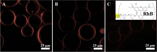
Representative fluorescence images of the RhB-linked gold-nanostructured droplets, measured (A) 1 day, (B) 7 days, and (C) 16 days after their creation. All of the images have the same intensity scale. The right inset schematically shows the chemical immobilization of RhB on a gold NP (not to scale).
The successful creation of functionalized droplets using the two-step approach widens the possibilities for biofunctionalization of the nanostructured droplet system. Moreover, it allows for the creation of biofunctionalized droplets with no soluble bioactive molecules in the aqueous phase, which could potentially block active sites on the cell surface and consequently prevent cell–droplet interactions. Inspired by this achievement, we used the human acute T cell leukemia cell line (Jurkat E6.1) to assess the potential ability of the nanostructured and biofunctionalized droplets to serve as a 3D APC analogue system. Jurkat T cells express the α4β1 and α5β1 integrins and exhibit activation-dependent regulation of integrin-mediated adhesion.35 Therefore, to provide cell interactions with nanostructured droplets, cyclic arginine-glycine-aspartic acid peptide c(RGDfK)-PEG6-cysteine was immobilized on PFPE–PEG–Gold surfactants via the cysteine thiol residue (see SI section 1.5).36 The peptide is specific against α5β1.
For cell-adhesion experiments, a mixture of PFPE–PEG–PFPE (20 mM) and PFPE–PEG–Gold–RGD (25 μM) was used to create biofunctionalized droplets. Jurkat E6.1 cells (6 × 10⁶ cells) were suspended in adhesion medium, which was used as an aqueous phase (see SI sections 2 and 3). Figure 5 shows a representative droplet ensemble with encapsulated Jurkat T cells (indicated by arrows). Strikingly, after incubation for 1 h, ∼90% of cells were observed to be in contact with the droplet’s periphery (Figure 5B). However, the cells encapsulated inside droplets without RGD-linked surfactants remained randomly distributed along the droplets, similar to our previous observations.29 The number of cells per droplet could be controlled by varying the initial number of cells added to the microfluidic channel. The cells demonstrated viability for up to 5 days of incubation (see SI section 3.2). This observation aligns well with previously reported results showing the viability of Jurkat cells for up to 9 days after encapsulation in 100 μm droplets made of triblock surfactants.30 The shorter viability period observed here is most likely due to lack of nutrition resulting from the 20-fold smaller droplet volume.
Figure 5.
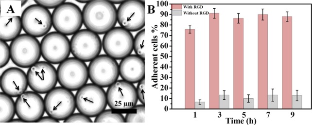
(A) Representative bright-field image of Jurkat E6.1 cells (indicated by arrows) in the cRGD-functionalized nanostructured droplets 6 h after their creation. (B) Quantification (adherent cell %) of Jurkat E6.1 cell adhesion on cRGD-functionalized (pink, left bars) and nonfunctionalized (gray, right bars) nanostructured droplets. Data are presented as means ± standard errors of the mean (n = 5).
To investigate further the cell–droplet interactions with high resolution, cell-containing droplets were freeze-fractured and investigated by cryo-SEM (see SI section 4.2). Cryo-SEM images at different magnifications (Figure 6A–D) show that all of the cells are spherical with diameters of 3–5 μm, similar to previous observations.37,38 Confirming the bright-field microscopy results, cell–droplet periphery interactions can easily be seen.
Figure 6.

Representative cryo-SEM micrographs of freeze-fractured biofunctionalized droplets after the Jurkat E6.1 cell adhesion experiment.
In conclusion, we have synthesized and developed gold-nanostructured and specifically biofunctionalized drops of water-in-oil emulsions that have the potential to serve as 3D APC analogues. The efficiency of the gold NPs in the nanostructured droplets to provide the required chemical and biological key functions of the APC has been presented and tested. Combining flexible biofunctionalization with the pliable physical properties of the nanostructured droplets can play a crucial role as it results in a flexible and modular system that closely models in situ APC–T cell interactions. Consequently, these systems will contribute to the understanding of how the force-dependent conformational changes during IS formation play a role in the transduction of costimulatory signals in T cells during the process of T-cell activation. The ability of T cells to exert forces in all three dimensions on the biomolecules held by the drop may also be important in evaluating the affinity and function of antigen receptors, which is not the case with T-cell studies on supported surfaces or bead-based APCs.7,12,25,39
Acknowledgments
I.P. thanks the Alexander von Humboldt Foundation for support. Part of this work was funded by the European Union Seventh Framework Programme (FP7/2007-2013) under Grants NMP4-LA-2009-229289 NanoII and NMP3-SL-2009-229294 NanoCARD. This work is also part of the CellNetwork Excellence Cluster at the University of Heidelberg and the National Institutes of Health (NIH) Common Fund Nanomedicine Program (PN2 EY016586). J.P.S. is the Weston Visiting Professor at the Weizmann Institute of Science. The authors thank Dr. Claire Cobley and Dr. Markus Axmann for detailed revision of the manuscript, Dr. Christian Boehm for fruitful discussions, and Professor Yeshayahu Talmon (Technion, Israel) for help with cryo-SEM.
Supporting Information Available
Experimental details and additional data. This material is available free of charge via the Internet at http://pubs.acs.org.
Author Contributions
† I.P. and J.-W.J. contributed equally.
The authors declare no competing financial interest.
Supplementary Material
References
- Alberts B.; Johnson A.; Lewis J.; Ralf M.; Roberts K.; Walter P.. Molecular Biology of the Cell, 4th ed; Garland Science: New York, 2002. [Google Scholar]
- Geiger B.; Spatz J. P.; Bershadsky A. D. Nat. Rev. Mol. Cell Biol. 2009, 10, 21. [DOI] [PubMed] [Google Scholar]
- Giannoni F.; Barnett J.; Bi K.; Samodal R.; Lanza P.; Marchese P.; Billetta R.; Vita R.; Klein M. R.; Prakken B.; Kwok W. W.; Sercarz E.; Altman A.; Albani S. J. Immunol 2005, 174, 3204. [DOI] [PubMed] [Google Scholar]
- Lillemeier B. F.; Mortelmaier M. A.; Forstner M. B.; Huppa J. B.; Groves J. T.; Davis M. M. Nat. Immunol. 2010, 11, 90. [DOI] [PMC free article] [PubMed] [Google Scholar]
- Manz B. N.; Groves J. T. Nat. Rev. Mol. Cell Biol. 2010, 11, 342. [DOI] [PMC free article] [PubMed] [Google Scholar]
- Vrljic M.; Nishimura S. Y.; Brasselet S.; Moerner W. E.; McConnell H. M. Biophys. J. 2002, 83, 2681. [DOI] [PMC free article] [PubMed] [Google Scholar]
- Alon R.; Dustin M. L. Immunity 2007, 26, 17. [DOI] [PubMed] [Google Scholar]
- Huppa J. B.; Davis M. M. Nat. Immunol. 2003, 3, 973. [Google Scholar]
- Lee K.; Holdorf A. D.; Dustin M. L.; Chan A. C.; Allen P. M.; Shaw A. S. Science 2002, 295, 1539. [DOI] [PubMed] [Google Scholar]
- Moss W. C.; Irvine D. J.; Davis M. M.; Krummel M. F. Proc. Natl. Acad. Sci. U.S.A. 2002, 99, 15024. [DOI] [PMC free article] [PubMed] [Google Scholar]
- Sakaguchi S.; Sakaguchi N. Int. Rev. Immunol. 2005, 24, 211. [DOI] [PubMed] [Google Scholar]
- Varma R.; Campi G.; Yokosuka T.; Saito T.; Dustin M. L. Immunity 2006, 25, 117. [DOI] [PMC free article] [PubMed] [Google Scholar]
- Tang Q.; Henriksen K. J.; Bi M.; Finger E. B.; Szot G.; Ye J.; Masteller E. L.; McDevitt H.; Bonyhadi M.; Bluestone J. A. J. Exp. Med. 2004, 199, 1455. [DOI] [PMC free article] [PubMed] [Google Scholar]
- Tarbell K. V.; Petit L.; Zuo X.; Toy P.; Luo X.; Mqadmi A.; Yang H.; Suthanthiran M.; Mojsov S.; Steinman R. M. J. Exp. Med. 2007, 204, 191. [DOI] [PMC free article] [PubMed] [Google Scholar]
- Haile L. A.; von Wasielewski R.; Gamrekelashvili J.; Krüger C.; Bachmann O.; Westendorf A. M.; Buer J.; Liblau R.; Manns M. P.; Korangy F.; Greten T. F. Gastroenterology 2008, 135, 871. [DOI] [PubMed] [Google Scholar]
- Jackson B. L.; Groves J. T. J. Am. Chem. Soc. 2004, 126, 13878. [DOI] [PubMed] [Google Scholar]
- Mossman K. D.; Campi G.; Groves J. T.; Dustin M. L. Science 2005, 310, 1191. [DOI] [PubMed] [Google Scholar]
- Groves J. T.; Ulman N.; Boxer S. G. Science 1997, 275, 651. [DOI] [PubMed] [Google Scholar]
- Lenhert S.; Sun P.; Wang Y. H.; Fuchs H.; Mirkin C. A. Small 2007, 3, 71. [DOI] [PubMed] [Google Scholar]
- Shen K. Y.; Tsai J.; Shi P.; Kam L. C. J. Am. Chem. Soc. 2009, 131, 13204. [DOI] [PMC free article] [PubMed] [Google Scholar]
- Spatz J. P.; Geiger B. Methods Cell Biol. 2007, 83, 89. [DOI] [PubMed] [Google Scholar]
- Hosseini B. H.; Louban I.; Djandji D.; Wabnitz G. H.; Deeg J.; Bulbuc N.; Samstag Y.; Gunzer M.; Spatz J. P.; Hammerling G. J. Proc. Natl. Acad. Sci. U.S.A. 2009, 106, 17852. [DOI] [PMC free article] [PubMed] [Google Scholar]
- Judokusumo E.; Tabdanov E.; Kumari S.; Dustin M. L.; Kam L. C. Biophys. J. 2012, 102, L5. [DOI] [PMC free article] [PubMed] [Google Scholar]
- O’Connor R. S.; Hao X. L.; Shen K. Y.; Bashour K.; Akimova T.; Hancock W. W.; Kam L. C.; Milone M. C. J. Immunol. 2012, 189, 1330. [DOI] [PMC free article] [PubMed] [Google Scholar]
- Turtle C. J.; Riddell S. R. Cancer J. 2010, 16, 374. [DOI] [PMC free article] [PubMed] [Google Scholar]
- Holtze C.; Rowat A. C.; Agresti J. J.; Hutchison J. B.; Angile F. E.; Schmitz C. H. J.; Köster S.; Duan H.; Humphry K. J.; Scanga R. A.; Johnson J. S.; Pisignano D.; Weitz D. A. Lab Chip 2008, 8, 1632. [DOI] [PubMed] [Google Scholar]
- Rowat A. C.; Bird J. C.; Agresti J. J.; Rando O. J.; Weitz D. A. Proc. Natl. Acad. Sci. U.S.A. 2009, 106, 18149. [DOI] [PMC free article] [PubMed] [Google Scholar]
- Schmitz C. H. J.; Rowat A. C.; Köster S.; Weitz D. A. Lab Chip 2009, 9, 44. [DOI] [PubMed] [Google Scholar]
- Hofmann T. W.; Hänselmann S. H.; Janiesch J. W.; Rademacher A.; Böhm C. H. J. Lab Chip 2012, 12, 916. [DOI] [PubMed] [Google Scholar]
- Clausell-Tormos J.; Lieber D.; Baret J. C.; El-Harrak A.; Miller O. J.; Frenz L.; Blouwolff J.; Humphry K. J.; Koster S.; Duan H.; Holtze C.; Weitz D. A.; Griffiths A. D.; Merten C. A. Chem. Biol. 2008, 15, 427. [DOI] [PubMed] [Google Scholar]
- Shah R. K.; Shum H. C.; Rowat A. C.; Lee D.; Agresti J. J.; Utada A. S.; Chu L.-Y.; Kim J.-W.; Nieves A.; Martinez C. J.; Weitz D. A. Mater. Today 2008, 11, 18. [Google Scholar]
- Dustin M. L. Immunol. Rev. 2008, 221, 77. [DOI] [PubMed] [Google Scholar]
- Vericat C.; Vela M. E.; Benitez G.; Carro P.; Salvarezza R. C. Chem. Soc. Rev. 2010, 39, 1805. [DOI] [PubMed] [Google Scholar]
- Ward W. W. In Green Fluorescent Protein: Properties, Applications, and Protocols, 2nd ed.; Chalfie M., Kain S. R., Eds.; Methods of Biochemical Analysis, Vol. 135; Wiley: Hoboken, NJ, 2006. [Google Scholar]
- Romzek N. C.; Harris E. S.; Dell C. L.; Skronek J.; Hasse E.; Reynolds P. J.; Hunt S. W.; Shimizu Y. Mol. Biol. Cell 1998, 9, 2715. [PMC free article] [PubMed] [Google Scholar]
- Barczyk M.; Carracedo S.; Gullberg D. Cell Tissue Res. 2010, 339, 269. [DOI] [PMC free article] [PubMed] [Google Scholar]
- Zhang C. G.; Xu Y. H.; Gu J. J.; Schlossman S. F. Proc. Natl. Acad. Sci. U.S.A. 1998, 95, 6290. [DOI] [PMC free article] [PubMed] [Google Scholar]
- Majstoravich S.; Zhang J. Y.; Nicholson-Dykstra S.; Linder S.; Friedrich W.; Siminovitch K. A.; Higgs H. N. Blood 2004, 104, 1396. [DOI] [PubMed] [Google Scholar]
- Grakoui A.; Bromley S. K.; Sumen C.; Davis M. M.; Shaw A. S.; Allen P. M.; Dustin M. L. Science 1999, 285, 221. [PubMed] [Google Scholar]
Associated Data
This section collects any data citations, data availability statements, or supplementary materials included in this article.