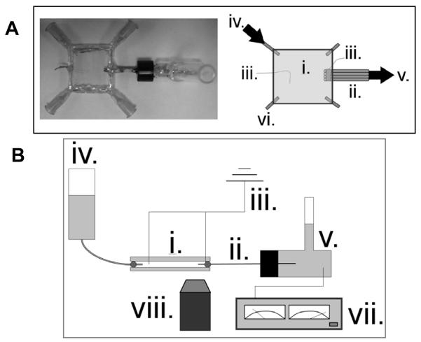
Figure 2.
(A) Top-view photo and schematic of glass plate device fabricated to image particles near a converging channel with electrode exactly at entrance. Hydrodynamic flow was from left inlet to right outlet. (B) Side-view schematic of experimental setup. A CCD camera attached to an epifluorescence microscope was used to capture fluorescent particle images. (i.) glass plate reservoir (ii.) 4-capillary bundle (iii.) electrode (iv.) inlet (v.) outlet (vi.) additional inlets/outlets (vii.) power supply (viii.) objective

