Abstract
We have designed, fabricated, calibrated and tested actuators for shear characterization to assess microscale shear properties of soft substrates. Here we demonstrate characterization of dry silicone and hydrated polyethelyne glycol. Microscale tools, including atomic force microscopes and nanoindenters, often have limited functionality in hydrated environments. While electrostatic comb-drive actuators are particularly susceptible to moisture damage, through chemical vapor deposition of hexamethyldisiloxane, we increase the hydrophobicity of our electrostatic devices to a water contact angle 90 ± 3°. With this technique we determine the effective shear stiffness of both dry and hydrated samples for a range of soft substrates. Using computational and analytical models, we compare our empirically determined effective shear stiffness with existing characterization methods, rheology and nanoindentation, for samples with shear moduli ranging from 5-320 kPa. This work introduces a new approach for microscale assessment of synthetic materials that can be used on biological materials for basic and applied biomaterials research.
Introduction
In this paper we present a microelectromechanical systems (MEMS) electrostatic Actuator for Shear Characterization (ASC; Figure 1) that effectively characterizes the microscale shear properties of hydrated samples. We have previously introduced our device and approach as a way to overcome the limitations often encountered when existing microcharacterization tools interface with hydrogels [1], and now we report the full characterization. Soft, hydrated samples are common in biology and biomedical research; however existing approaches and micro-characterization tools face challenges in characterizing hydrated biological materials. Most soft tissues in the body have high water content, therefore hydrogels and other soft substrates are often used in vitro to study single- and multi-cellular behavior. Hydrogels like polyethylene glycol (PEG) can be made to mimic the material properties of tissues and are used specifically to examine cellular response to these properties. To fully understand the effect of substrate stiffness on cells, though, the substrate must be effectively characterized in hydrated environments. Despite the popularity of these hydrogel experimental platforms, characterizing their material properties remains challenging.
Figure 1.
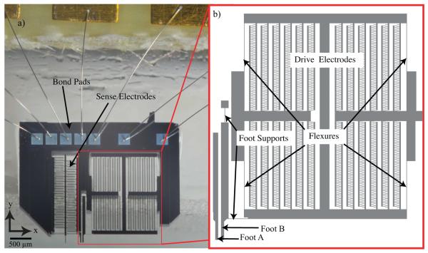
Photograph and enlarged model of actuator for shear characterization. (a) The ASC is driven electrostatically by voltage applied to the device through bond pads and wire bonds. (b) Enlarged model of the drive electrodes, which are supported by four flexures and separated from the remainder of the device. These flexures are representative of springs in parallel with a total stiffness represented as kspring. The actuator foot is connected to a base, and to the drive electrodes via the two-foot supports as shown. The operation principle of ASC relies on electrostatic force generation where the drive electrodes move Foot B to the left. In this depiction Foot A is removed from the remainder of the device and appears to be floating; however, it is always stationary.
While rheometers are often used to characterize soft, hydrated samples in shear, most rheology systems are unable to capture microscale behavior. The resolution of these systems is based on the geometry of the punch, typically larger than 1 mm in diameter, where larger surfaces and volumes increase the accuracy of the results. Microrheology, which utilizes optical detection of moving tracer particles [2], tends to characterize shear properties in the bulk of the material rather than at the surface. Other microscale tools characterize substrates in the normal direction. Atomic force microscopy (AFM) and nanoindentation provide methods for determining substrate resistance to penetration at a localized point, and an elastic modulus can be extracted using modified Hertz contact models [3, 4]. While the traditional compliance-based approach used for nanoindenters is suitable to study metals, ceramics, and other stiff materials, this approach is often challenging to use on soft hydrogels, since these materials have high adhesion energies and viscoelastic responses [5]. In both AFM and nanoindentation, high surface energy significantly increases tip-substrate interaction, creating computational errors of increased apparent stiffness due to pull-off miscalculations [6, 7] and overestimation of elastic moduli due to contact point misidentification [8]. It is also important to maintain hydration of the hydrogels during measurements since dehydrating conditions can result in observed stiffness up to three orders of magnitude larger than the hydrated stiffness [9] and rehydrated samples often remain stiffer than their pre-dehydrated conditions [10].
Many MEMS devices have been designed and fabricated to characterize samples not suited for AFM and nanoindentation [11]. However, most of these tools are designed to operate in dry environments. Electrostatic devices, in particular, are susceptible to moisture damage (reviewed in Maboudian and Howe [12]). We chose to demonstrate this new method of characterization on PEG, a popular synthetic hydrogel because of its biocompatibility, flexibility, and Food and Drug Administration (FDA) approval for clinical use in humans [13]. PEG has been used in mechanobiology to study the effect of matrix stiffness on the spontaneity of cardiac contraction [14], in drug delivery as a 3D scaffold for cell encapsulation [15-17], and in many other tissue-engineering applications [18]. The ASC design leverages chemical surface modifications of the device to keep the electrostatic combs dry while interacting with a hydrated sample. We employ both computational and analytical models to compare device performance to common characterization methods.
Design, operating principle, and fabrication
We based our micro-electrostatic tool and design on a new concept of operation for assessing microscale surface shear properties under hydrated conditions. The device was designed to apply shear loading on soft, hydrated samples while detecting the vertical contact force. Note, a mask error prevented testing of the vertical sensing features seen on the left side of the device image in Figure 1; however, the device can still be positioned vertically and operated as described here. The ASC operates while placed perpendicular to the substrate such that the electrostatic comb drives exert μN shear forces on the substrate surface (Figure 2). Foot A remains stationary while Foot B is driven by the electrostatic actuator; feet are 30 × 15 μm2 spaced 70 μm apart. The flexures that provide mechanical support to the moving shuttle are designed to be 9 times stiffer in the out-of-plane direction, ensuring that movement of Foot B is constrained laterally. Additionally, foot supports (Figure 1b) mediate the effects of off-axis forces on Foot B. The variables and values introduced for the ASC in the following sections are defined in Table 1.
Figure 2.
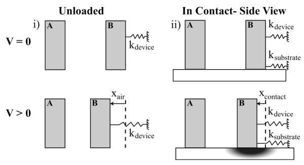
Schematic of ASC shows unloaded operation and the loaded configuration for characterization of substrate. The top row represents V = 0 where no electrostatic force is applied while the bottom represents an applied voltage, V>0. (i) Unloaded condition where device is not in contact with the substrate. Here, the dominant spring constant is that of the flexures supporting the movable actuator Foot B. (ii) Loaded condition in contact with the substrate. Here, the system is modeled as two springs in parallel. Applied voltage initiates displacement of the tip and subsequent substrate deformation. No-slip conditions were verified by tracking fiducial markers (fluorescent beads) in the substrate.
Table 1.
Descriptions and values for analytical model of ASC operation
| Description | Symbol | Value(s) |
|---|---|---|
| Number of comb pairs | N | 1000 |
| Permittivity in air | ε | 8.85 × 10⁻¹² F/m |
| Empirically determined constant for electrical force |
α | 0.019 μN/V |
| Analytically derived basic constant for electrical force |
α basic | 0.010 μN/V |
| Analytically derived comprehensive constant for electrical force |
α comprehensivee | 0.048 μN/V |
| Voltage | V | 0 - 50 V |
| Distance between electrodes | d | 8 μm |
| Width of electrodes | w | 4 μm |
| Length of electrodes overlap | l | 2 - 12 μm |
| Thickness of electrodes | t | 15 μm |
| Spring elongation | xcontact | 0 - 10 μm |
| Device stiffness theoretical | kdevice_th | 0.15 - 0.67 N/m* |
| Device stiffness calibration | kdevice_cal | 0.54 ± 0.04 N/m |
Range determined by uncertainty analysis of fabrication tolerances
Operating principle of substrate shear characterization
For interdigitated comb fingers supported by silicon flexures, the electrical force can be written as an empirically determined constant, β, multiplied by the applied voltage squared [19],
| (1) |
For a simple analytical model of a longitudinal electrostatic comb drive [20]
| (2) |
where, N is the number of finger pairs, t is the thickness of the device layer, ε is the dielectric constant and d is distance between the electrodes. However, this simplified analytical model does not account for fringe fields. An example of an alternate model that assumes strong fringe field effects yields another estimate [21, 22],
| (3) |
where, w is the width of the electrodes. In our system, assuming a no-slip configuration when the device is in contact with the substrate, any displacement of the actuator tip (xcontact) is identical to the displacement of the surface directly below the actuator tip. Thus, the device flexures (kdevice) and substrate elasticity (ksubstrate) can be treated as two sets of springs in parallel, and Fmechanical is given as
| (4) |
The device spring constant, kdevice, was predicted for 4 springs in parallel using Euler-Bernoulli beam theory [23-25] for the entire flexure (Equation 5) as
| (5) |
Since the mechanical and electrical forces are equivalent under steady state operating conditions, the material property, ksubstrate, is extracted by rearranging the force balance to attain
| (6) |
Fabrication
The device was fabricated on silicon-on-insulator (SOI) wafers with device layer thickness of 15 μm p-type boron-doped to 0.0025 Ω-cm, buried oxide of 1 μm, and an undoped handle layer of 400 μm (Figure 3). This fabrication process was adapted from the three lithographic step process used by Mukundan et al. [26]: 1) to define sputtered aluminum electrical contacts; 2) to pattern the frontside etching of devices in the handle layer using deep reactive ion etching (DRIE); and 3) to pattern the backside to release the devices using DRIE. After liquid hydrofluoric acid etching and critical point drying, we adhered the released device to a polymethyl-methacrylate board for ease of handling and wirebonded to a surface mount board with connections to power and readout circuitry. Using a custom LabVIEW® 8.6 interface and DAQ-D6036E, we controlled the voltage range, duration and step size. The signal was then amplified by 15× through a Kepco (Flushing, NY) power amplifier.
Figure 3.
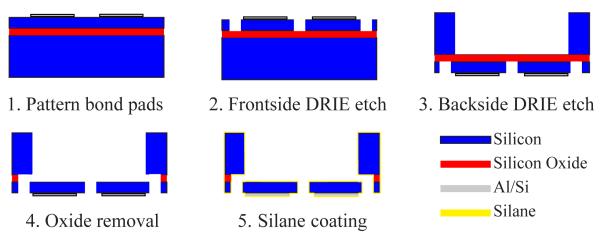
Fabrication steps for the ASC begin with an SOI wafer having a highly-doped 15 μm device layer and an undoped 400 μm handle wafer. Here the schematic is shown for a single device on the SOI wafer. (1) After patterning 99% Al-1% Si bond pads, (2) DRIE defines the comb structure on the frontside and (3) open regions on the backside directly under the floating structures. (4) The 1 μm buried oxide layer is wet etched away and the entire SOI wafer is dried via critical point drying. (5) Individual devices are removed from the SOI wafer and are coated with a protective layer of HMDS silane.
To protect our device from water damage during interaction with hydrated samples, we treated our devices with a hydrophobic molecule, hexamethyldisiloxane (HMDS). Vapor deposition of HMDS (Sigma-Aldrich®, St Louis, MO) successfully avoided device stiction that occurs from common immersion methods. We first desiccated the device for 12 hours in a sealed glass chamber containing 25 grams of phosphorus pentaoxide (P2O5) powder (Sigma-Aldrich®, St Louis, MO). Desiccation prevented agglomeration of HMDS and non-uniform layers induced by moisture [27]. We then transferred the device to another sealed glass chamber containing 50 μl of HMDS for another 12 hours. During each experiment both chambers were enclosed in aluminum foil to block ambient light. A similar HDMS treatment was been reported to last for four months [28].
Device characterization
Surface treatment characterization
After treatment with HMDS, the surface contact angle increased to 90 ± 3° from an untreated value of 30 ± 3° (Cam-Wafer Contact Angle Machine, Tantec, Lunderskow, Denmark). These results are comparable to reported values of 94-110° for other self-assembly conditions [29]. We also measured an average root-mean-square roughness of 2.5 nm after treatment using atomic force microscopy (AlphaSNOM300a WiTec, Ulm, Germany), which differed from the untreated roughness of 0.8 nm. This treated value is comparable to published values of 2.55-3.27 nm after HMDS treatment [30]. Direct water testing of the devices also confirmed device hydrophobicity. When a drop of water was placed directly on the combs of the ASC, the hydrophobic coating drove beading and expulsion of water out of the combs in five successive trials (monitored with upright microscope DMRXA2, Leica Microsystems and Digital Camera C10600, Hamamatsu) (Supplementary Information: Video 1). The ASC is not designed to be submerged in media; rather, the long feet and hydrophobic barrier prevent water from wicking up into the combs. The ASC can thus operate near wetting surfaces to measure local shear stiffness of hydrogels.
Device stiffness characterization
Due to the inherent uncertainty in our fabrication processes, we empirically measured the ASC’s stiffness with a calibrated piezoresistive microcantilever [31]. The theoretical stiffness (Equation 5) and root-mean-sum of squares uncertainty in kdevice was 0.72 ± 0.65 N/m based on expected ± 0.5 μm dimensional tolerances for lithographic and etching steps. To determine the ASC stiffness more precisely, we used a piezoresistive microcantilever (750 μm long × 7 μm thick × 30 μm wide) with a calibrated stiffness value of 0.779 N/m. In brief, tip deflection was converted into voltages via an instrumentation amplifier (AD8221, Analog Devices, MA), a custom printed circuit board with a Wheatstone bridge, and an 8 kHz first order low pass filter [31]. After 1000× gain, the force sensitivity of the piezoresistive microcantilever was 512.9 V/N.
Under a stereomicroscope at 60× magnification, we placed the tip of the cantilever against the base of the ASC foot (Figure 4). In this configuration, we could manipulate the cantilever die using a piezoelectric actuator stage with a 100 kHz feedback loop, while monitoring the output of the piezoresistive cantilever. In this manner, we could place the tip gently in contact with the ASC foot using a motorized z-linear stage (T-LA50-S Zaber Technologies, Canada) and zero the output of the Wheatstone bridge. We then applied a known displacement to the cantilever die while measuring the force through the series springs of the cantilever and ASC. The calibrated stiffness of the ASC was 0.54 ± 0.04 N/m (mean ± s.d., n = 4 replicate measurements), which was within the tolerance for the analytical spring stiffness.
Figure 4.
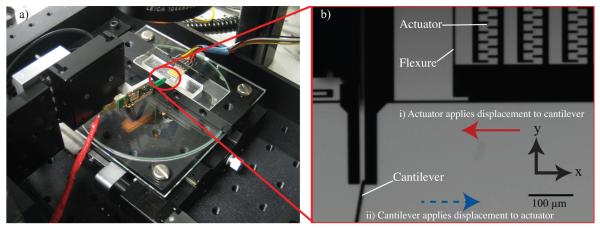
(a) Experimental setup for calibration of the electrostatic actuator. (b) Magnified image highlights details of calibration with piezoresistive cantilever. (i) Voltage is applied to the device to displace actuator in the direction of the solid red arrow while the cantilever is held stationary. The deflection signal of the piezoresistive cantilever indicates force-voltage relationship of ASC is β = 0.019 μN/V2. (ii) To measure the passive spring stiffness of the device (kspring), the linear actuator moves the cantilever in the direction of the blue dotted arrow while the device is held stationary on the stage. The device stiffness is extracted from these data, where kdevice = 0.54 N/m. The apparent cantilever stiffness caused by the 10° offset from the vertical orientation was accounted for as noted by Park et al [31].
Force characterization
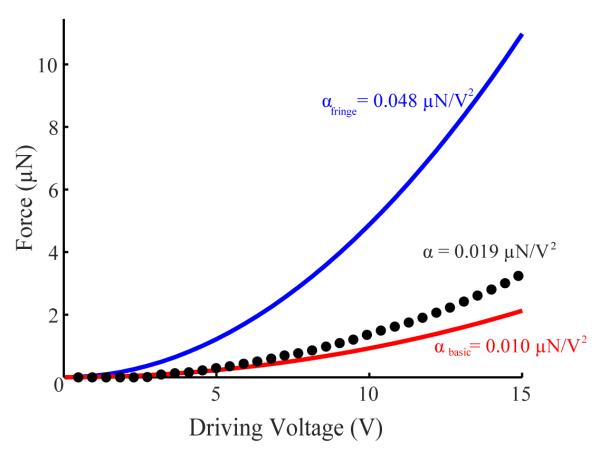
Using this same configuration but now driving the ASC, we measured the force-voltage (F-V) relationship of our device with the same cantilever (Figure 5 + Supplementary Information: Video 2). Fitting this quadratic curve, the coefficient describing the F-V relationship was β = 0.019 μN/V2 (R2 = 0.996). However, at low voltages (<4 V), the force was close to zero. We confirmed that this initial behavior was not due to surface charge accumulation by repeatedly increasing and decreasing the applied voltage, at a rate less than 1 Hz. We also observed that device force and displacements yielded no appreciable hysteresis. While the empirical β curve lagged behind the βbasic curve at low voltages, β exceeded βbasic above 4 V. This displacement lag at low voltages is likely due to the small initial overlap distance between the comb fingers. With increasing voltage, the comb fingers overlap increased and the effects of fringe fields began to contribute significantly to the overall force generated. These forces helped to increase the empirical curve above the βbasic curve, but not as great as in βfringe. From calibration we determined a minimum force of 43 nN for the ASC and maximum force error within 4.8% of the empirically determined applied force.
Figure 5.
Force-voltage (F-V) relationship of ACS exhibits expected quadratic behavior. A calibrated piezoresistive cantilever was used to quantify the resulting force due to voltage applied to the ACS (dotted black curve). The best fit of the entire curve produced β = 0.019 μN/V2 (R2 = 0.996). Small initial displacements are due to initial overlap of the electrodes (2 μm) and suggest an operating range above 5 V. The empirical data falls between a basic analytical model that ignores fringe fields (βbasic = 0.010 μN/V2) and a comprehensive alternate model [21,22] yielding βfringe = 0.048 μN/V2.
We also compared the empirically determined F-V relationship to the two commonly analytical models introduced earlier (Equation 2) and (Equation 3), using the values described in Table 1. The basic analytical model for comb drive electrostatic actuators [20] yields βbasic = 0.010 μN/V2 while the alternate model, which includes fringe field effects [21, 22], yields βfringe = 0.048 μN/V2. The empirical device performance (β = 0.019 μN/V2) falls between a basic model that ignores fringe fields and the alternate model that incorporates strong fringe electric fields (Figure 5).
The overall yield of packaged and treated devices available for testing was only 16%. The major causes of device losses were errors in the mask design, damages during fabrication (particularly after removing the buried oxide layer), and difficulties with several post fabrication processes. For example experimenting with various hydrophobic treatments, calibrating the device with the piezoresistive cantilever calibration and calibrating polyacrylamide gels using the ASC. In total there were 12 different actuator designs and we found three designs had spring stiffness and force generation capabilities suitable for the substrates we tested.
Results and discussion
Silicone shear characterization with nanoindentation and computational modeling validates utility of ASC
To confirm the utility of ASC, we compared data obtained from our approach to computational data where the material properties of silicone were obtained by standard nanoindentation techniques. For these experiments we used a 250 μm thick commercial elastomeric silicone polymer (HT-6240, Stockwell Elastomerics, Philadelphia, PA). The polymer was chosen for its transparency and negligible water content.
We investigated the silicone polymer via microscale indentation. For the microscale indentation we used an MTS Nanoindenter® XP (Eden Prairie, MN) with a 500 μm diameter flat punch at an indentation speed of 120 nm/s and indentation depth of 6 μm. Using the Oliver Pharr expression [32, 33], we extracted a Young’s Modulus, E, for the silicone samples of 0.93 ± 0.08 MPa (mean ± s.d., n = 6), suggesting a shear modulus of ~320 kPa assuming near incompressibility (v = 0.49).
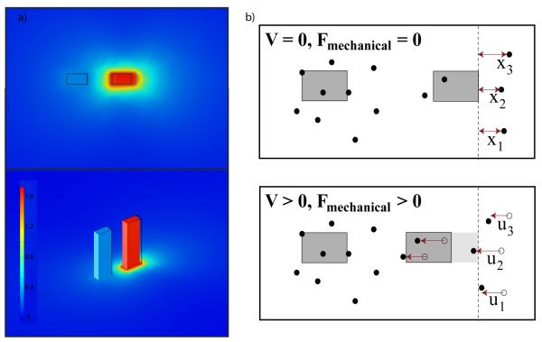
To computationally compare the effective stiffness determined by the ASC to this microscale indentation value, we modeled our approach in COMSOL 4.0 (Figure 6a). The silicone substrate was modeled using the Structural Elements physics category and Solid Mechanics (solid) subcategory. We used a Stationary Study to evaluate the model. The silicone was modeled as a flat, linear elastic homogeneous substrate with elastic modulus E = 0.93 MPa, as empirically derived from nanoindentation experiments, and a Poisson’s ratio of v = 0.49, a commonly used value for similar elastic solids [34, 35]. The substrate depth was 1 mm, with its length and width infinitely large compared to the ASC feet. We modeled the feet on top of the silicone as rigid bodies with two 30 × 15 μm2 surfaces with a 70 μm distance between the feet, as on the actual device. To simulate the observed no-slip condition under the feet, we formed a union between the feet and silicone surfaces with a relative repair tolerance of 1 μm. The feet were infinitely tall and stiff in comparison to the silicone. We constrained the bottom of the silicone while we applied 45 μN of shear Face Load distributed at the interface between one of the feet surfaces and the substrate; the other foot was kept stationary. We applied the Free Tetrahedral mesh across the entire geometry with the mesh size predefined as normal.
Figure 6.
(a) Computational modeling of the silicone (Stockwell Elastomerics) under shear loading exerted by the feet of the ASC. While no shear loads are applied to the stationary foot, 45 μN of shear force applied to the moveable actuator foot results in a displacement of 1.73 ± 0.1 μm. The top image is a top down view of the displacement, while the bottom image is an isometric view, and contains the color-coded displacement scale bar. To enhance visualization, the deflection was scaled up by 2.5x. (b) The ASC utilizes fiducial marker tracking to correlate effective shear stiffnes to a shear modulus, G. The moveable ASC foot (grey box, right) displaces laterally under applied voltage, applying a known force to the gel surface. Gel deformation is characterized by optically tracking embedded beads. The location of beads, xi, and projection of displacement, ui, in the direction of force, Fmechanical, are used with Equation 7 to derive shear modulus from ASC experiments. Beads directly behind the foot, e.g. bead 2, were used preferentially in calculating G to satisfy point force assumptions.
The displacements of the computational model were consistent with empirical observations. For 45 μN of tangential surface forces, the computational model and ASC experiments had displacements of 1.73 ± 0.1 μm and 1.4 ± 0.5 μm (mean ± s.d.), respectively. These experimental data were obtained with five measurements taken >0.5 mm apart from one another on a continuous silicone sample. These results validated our computational method for correlating the effective stiffness (ksubstrate in N/m) as determined by ASC to well known material properties. In these experiments, the in plane stiffness, ksubstrate = 25.47 ± 1.42 N/m corresponded with an elastic modulus of 0.93 MPa for the modeled silicone polymer.
Analytical model of hydrogels correspond to ASC results
To use the ASC to characterize hydrated substrates, we fabricated polyethylene glycol (PEG) hydrogels and correlated the ASC results with shear modulus using an analytical model. The hydrogels were made by diluting PEG diacrylate (Mn = 700, Sigma-Aldrich®, St Louis, MO) to the desired concentrations (8 wt% and 10 wt%) in phosphate buffered saline (Invitrogen, Carlsbad, CA) containing 0.05 wt% 2-methyl-1-[4-(hydroxyethoxy)phenyl]-2-methyl-1-propanone (I2959, Ciba Specialty Chemicals, Tarrytown, NY). Rain-X coated slides (Rain-X® Houston, TX) were fixed at 1 mm apart, and 625 μl of each PEG solution was injected between the parallel glass slides. Both the 8 wt% and 10 wt% gels contained a low density (10−5 ratio solid vol/vol) of 2.7 μm diameter green fluorescent beads (Duke Scientific, Palo Alto, CA). To promote migration of the beads to the bottom glass surface, the suspension was left undisturbed for 10 minutes. The gels were then polymerized under ultraviolet light exposure at 20 mW/cm2 for 10 minutes (λUV centered at = 383 nm).
We attempted nanoindentation experiments on the polyethylene glycol (PEG) gels, but unsurprisingly, the system was unable to stabilize during the surface approach. Sample compliance, nanoindenter stability range, and receding water meniscus make hydrogels difficult to measure with this apparatus. We instead used rheology (TA AR2000, TA Instruments, New Castle DE) to determine its shear modulus, G. Shear moduli were measured at 0.3% strain rate and were consistent for frequencies tested (0.1-10 Hz). The shear moduli of 8 wt% and 10 wt% PEG gels were found to be G8wt% = 5.13 ± 0.31 kPa and G10wt% = 9.27 ± 1.70 kPa (n = 3 samples).
To correlate data obtained using the ASC with rheological measurements, we used the approach to Cerruti’s problem [36, 37] to calculate shear modulus, G. Cerruiti’s problem states that for an isotropic linear elastic material, the greater the distance between a particle and a point force, the less that particle moves. When operating the ASC at small displacements (< 5μm) on thick, homogeneous PEG gels at a rate of <5 μm/s, these constraints are met and this equation can be used to estimate the shear modulus of the elastic half-space. To use this model on PEG gels, we observed the location and corresponding displacements of fluorescent beads on the surface of the substrate (Figure 6b). Bead displacements underneath the foot matched the observed foot displacement, confirming a no-slip condition. We assume the force exerted by the ASC foot, at the trailing edge of the moving foot, can be modeled as a point force (Fmechanical) at x = 0, and the shear modulus, G, is given as a function of the x-component displacement, u, of a point located at some distance, x, from Fmechanical:
| (7) |
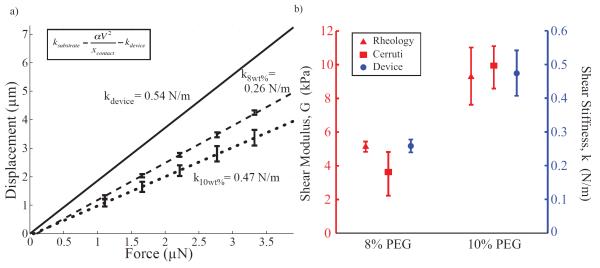
Using this model, we extracted a shear moduli GCerruti of 8 wt% and 10 wt% PEG gels as 3.57 ± 1.30 kPa and 9.89 ± 1.26 kPa, respectively. These values are consistent with our results by rheology (Figure 7a). Student’s t-tests of GCerruti and GRheology confirmed that there were no significant differences between each of the 8 wt% and 10 wt% concentrations with p-values of p8wt% = 0.167 and p10wt% = 0.637.
Figure 7.
Characterization of PEG hydrogels. (a) The ASC device is capable of determining the effective stiffness of various cross-linker concentrations of PEG gels. Optical observation of displacements under the microscope for various force loading conditions was used to calculate the effective stiffness of substrates. The solid black line the linear fit of the device displacement in the unloaded state. These results also show that k10wt% (dotted black line) has a higher effective stiffness than k8wt% (dashed black line) for PEG gels (0.47 ± 0.06 N/m and 0.26 ± 0.02 N/m respectively). Note that stiffer substrates result in less displacement. Error bars show standard deviation of empirical measurements at representative voltages across all samples tested (n = 5). (b) Comparison of shear moduli of 8 wt% and 10 wt% PEG gels based on empirical ASC data and rheological measurements. Rheology and obervations of displacements used for Cerruti’s formulation provide estimates of shear modulus (left axis, n = 3 samples), while the ASC provides shear stiffness (right axis, n = 5) confirmed to correlate appropriately with G through a computational model.
With the ASC, we determined in plane ksubstrate values of k8wt% = 0.26 ± 0.02 N/m and k10wt% = 0.47 ± 0.06 N/m (mean ± s.d., n = 5) (Figure 7b). When applying the Student’s t-test to compare k8wt% to k10wt%, we detected significant differences between the two samples (p = 0.012 for a one-sided test). This p-value was the same order of magnitude to the p-value from comparing G8wt%Rheology and G10wt%Rheology (where p = 0.024). Thus, local substrate shear stiffness characterized by the ASC was determined to be a reasonable proxy for shear modulus characterized globally by rheology, which can be useful to study local material behavior of heterogeneous substrates.
Conclusions
We have designed and demonstrated a system capable of characterizing surface shear behavior of polymers and hydrogels at the microscale. We calibrated a custom electrostatic actuator and used it to characterize a silicone polymer and hydrated PEG. Using material properties information attained from nanoindentation of the silicone polymer, we derived computational results that were consistent with the shear characterization results achieved with our method. The hydrophobic treatment of the actuator allowed probing of wet samples without succumbing to stiction. Our method was able to characterize the in plane stiffness of varying concentration of PEG and detect differences between their stiffness.
Our MEMS-based approach to shear characterization provides a unique approach to investigate microdomains of soft, wetted samples. Through surface treatments, we have overcome the typical challenges of MEMS device stiction in hydrated environments, allowing for characterization of hydrogels and biological samples. By calibrating the device, we are able to apply precise (nN range) forces up to 45 μN and investigate the shear response for substrates ranging from G = 5-320 kPa. This device and method enables a wide range of synthetic and biological materials to be characterized.
Future Outlook
We have demonstrated an approach for characterizing soft materials based on three basic principles: a MEMS-based actuator, a surface coating to control adhesion and wetting, and optical monitoring of displacements. In this work, we apply these principles for successful characterization of silicone and hydrated PEG. This generalized approach of interfacing MEMS devices is not limited to PEG but rather the larger category of hydrogels and soft materials. Polyacrylamide gels, for example, are often used for investigating cell-substrate interactions including adhesion force studies, migration and proliferation studies, and cell morphology and differentiation [38-40]. However, we found that polyacrylamide gels exhibited undesirable adhesion to silicon, and thus damaged several devices during the attempted polyacrylamide calibration. In the future, a surface treatment specifically designed to reduce adhesion between the actuator and acrylamide functional groups would enable characterization of this commonly used substrate.
In addition to characterizing culture substrates, this generalized approach could be used to characterize biological samples directly. Integration of displacement- and force- sensing features onto the MEMS device would extend the application of this approach to non-transparent substrates. Furthermore, horizontal force and displacement sensors would permit characterization of traditional time-dependent shear properties with cyclically applied loads. For example, such MEMS-based approaches could detect spatial changes in shear properties of cartilage to understand disease progression in osteoarthritis [41], of tumors to inform cancer treatments [42], or of blood vessels for insights into atherosclerosis [43]. While many microscale tools for indentation exist, we have demonstrated a MEMS-based system for shear characterization that enables high spatial resolution for probing the top surface of the substrate.
Supplementary Material
Acknowledgements
The authors acknowledge support from the California Institute for Regenerative Medicine (CIRM RC1-00151-1), the National Science Foundation (EFRI-CBE 0735551, EFRI-MIKS 1136790, ECS-0449400), the National Institutes of Health (R01 EB006745-01A1, R33 HL089027), the Defense Advanced Research Projects Agency (YFA N66001-09-1-2089), and Stanford Bio-X. Individual authors were supported by Stanford Graduate Fellowship program (GCH), and NSF Graduate Research Fellowship, Smittcamp Cardiovascular Institute Fellowship, and Stanford VPGE DARE Fellowship (CSS). Work was performed in part at the Stanford Nanofabrication Facility (a member of the National Nanotechnology Infrastructure Network), which is supported by the National Science Foundation under Grant ECS-9731293, its lab members, and the industrial members of the Stanford Center for Integrated Systems. The authors would also like to thank Prof. Olav Solgaard and Karthik Vijayraghavan for helpful discussions on the development and fabrication of the device, Vikram Mukundan for helpful discussions about device testing and characterization, and Prof Bill Nix and Lucas Berla for assistance and advice with nanoindentation characterization.
References
- [1].Higgs G, Simmons C, Fried A, Pruitt BL. Microfabricated Calibration Tool for Direct Shear Stiffness Measurements with Applications in Cell Mechanics. Sensors. 2010:2478–81. [Google Scholar]
- [2].Brau RR, Ferrer JM, Lee H, Castro CE, Tam BK, Tarsa PB, Matsudaira P, Boyce MC, Kamm RD, Lang MJ. Passive and active microrheology with optical tweezers. Journal of Optics A Pure and Applied Optics. 2007;9:S103–S12. [Google Scholar]
- [3].Tranchida D, Piccarolo S, Soliman M. Nanoscale Mechanical Characterization of Polymers by AFM Nanoindentations : Critical Approach to the Elastic Characterization. Macromolecules. 2006;39:4547–56. [Google Scholar]
- [4].Chizhik SA, Huang Z, Gorbunov VV, Myshkin NK, Tsukruk VV. Micromechanical Properties of Elastic Polymeric Materials As Probed by Scanning Force Microscopy. Langmuir. 1998;14:2606–9. [Google Scholar]
- [5].Ebenstein DM, Pruitt LA. Nanoindentation of biological materials. Nano Today. 2006;1:26–33. [Google Scholar]
- [6].Lin DC, Horkay F. Nanomechanics of polymer gels and biological tissues: A critical review of analytical approaches in the Hertzian regime and beyond. Soft Matter. 2008;4:669. doi: 10.1039/b714637j. [DOI] [PubMed] [Google Scholar]
- [7].Gupta S, Carrillo F, Li C, Pruitt L, Puttlitz C. Adhesive forces significantly affect elastic modulus determination of soft polymeric materials in nanoindentation. Materials Letters. 2007;61:448–51. [Google Scholar]
- [8].Kaufman JD, Klapperich CM. Surface detection errors cause overestimation of the modulus in nanoindentation on soft materials. Journal of the mechanical behavior of biomedical materials. 2009;2:312–7. doi: 10.1016/j.jmbbm.2008.08.004. [DOI] [PubMed] [Google Scholar]
- [9].Masuike T, Taki S, Hara K, Kai S. Change of Temperature and Elastic Stiffness during Dehydration Process of Polyacrylamide Gel. J. Appl. Phys. 1995;34:4997–5000. [Google Scholar]
- [10].Balooch M, Wu-Magidi IC, Balazs A, Lundkvist AS, Marshall SJ, Marshall GW, Siekhaus WJ, Kinney JH. Viscoelastic properties of demineralized human dentin measured in water with atomic force microscope (AFM)-based indentation. Journal of Biomedical Materials Research. 1998;40:539–44. doi: 10.1002/(sici)1097-4636(19980615)40:4<539::aid-jbm4>3.0.co;2-g. [DOI] [PubMed] [Google Scholar]
- [11].Haque MA, Saif MTA. A review of MEMS-based microscale and nanoscale tensile and bending testing. Experimental Mechanics. 2003;43:248–55. [Google Scholar]
- [12].Maboudian R, Howe RT. Critical Review: Adhesion in surface micromechanical structures. Journal of Vacuum Science and Technology B: Microelectronics and Nanometer Structures. 1997;15:1. [Google Scholar]
- [13].Harris JM, Chess RB. Effect of pegylation on pharmaceuticals. Nature Reviews Drug Discovery. 2003;2:214–21. doi: 10.1038/nrd1033. [DOI] [PubMed] [Google Scholar]
- [14].Shapira-Schweitzer K, Seliktar D. Matrix stiffness affects spontaneous contraction of cardiomyocytes cultured within a PEGylated fibrinogen biomaterial. Acta Biomaterialia. 2007;3:33–41. doi: 10.1016/j.actbio.2006.09.003. [DOI] [PubMed] [Google Scholar]
- [15].Nicodemus GD, Bryant SJ. Cell Encapsulation in Biodegradable Hydrogels for Tissue Engineering Applications. Tissue engineering Part B Reviews. 2008;14:149–65. doi: 10.1089/ten.teb.2007.0332. [DOI] [PMC free article] [PubMed] [Google Scholar]
- [16].Zhang G, Wang X, Wang Z, Zhang J, Suggs L. A PEGylated fibrin patch for mesenchymal stem cell delivery. Tissue Engineering. 2006;12:9–19. doi: 10.1089/ten.2006.12.9. [DOI] [PubMed] [Google Scholar]
- [17].Allen TM, Cullis PR. Drug delivery systems: entering the mainstream. Science. 2004;303:1818–22. doi: 10.1126/science.1095833. [DOI] [PubMed] [Google Scholar]
- [18].Nguyen KT, West JL. Photopolymerizable hydrogels for tissue engineering applications. Biomaterials. 2002;23:4307–14. doi: 10.1016/s0142-9612(02)00175-8. [DOI] [PubMed] [Google Scholar]
- [19].Tang W, Nguyen T, Howe R. Laterally Driven Polysilicon Resonant Microstructures. Sensors And Actuators. 1989;20:25–32. [Google Scholar]
- [20].Motamedi ME. MOEMS: micro-opto-electromechanical systems. Optical Engineering. 2005;36:3505. [Google Scholar]
- [21].Johnson WA, Warne LK. Electrophysics of micromechanical comb actuators. Journal Of Microelectromechanical Systems. 1995;4:49–59. [Google Scholar]
- [22].Liu C. Foundations of MEMS. vol 8. Pearson Education, Inc.; 2006. [Google Scholar]
- [23].Gere JM, Timoshenko SP. Mechanics of Materials. PWS Publishing Company; 1997. [Google Scholar]
- [24].Roark RJ, Young WC. Formulas for stress and strain. vol 6. McGraw-Hill; 1975. [Google Scholar]
- [25].Young WC, Budynas RG. Roark’s Formulas for Stress and Strain. vol 7. McGraw-Hill; 2002. [Google Scholar]
- [26].Mukundan V, Pruitt BL. MEMS Electrostatic Actuation in Conducting Biological Media. Journal Of Microelectromechanical Systems. 2009;18:8. doi: 10.1109/JMEMS.2009.2013398. [DOI] [PMC free article] [PubMed] [Google Scholar]
- [27].Srinivasan U, Houston MR, Howe RT, Maboudian R. Alkyltrichlorosilane-based self-assembled monolayer films for stiction reduction in silicon micromachines. Journal Of Microelectromechanical Systems. 1998;7:252–60. [Google Scholar]
- [28].Carvalho ATD, Carvalho RAM, Silva MLPD, Demarquette NR. Hydrophobic plasma polymerized hexamethyldisilazane thin films: characterization and uses. Materials Research. 2006;9:9–13. [Google Scholar]
- [29].Pereira GJ, Da Silva MLP, Tan IH, Gouvea D. Modification of surface properties of alumina by plasma treatment. Journal of Materials Chemistry. 2000;10:259–61. [Google Scholar]
- [30].Tomkute V, Beganskiene A, Kareiva A, Jokhadar SZ, Batista U. Synthesis and Investigation of Modified Silica Coatings for Biotechnology. Chemistry, physics and technology of surface. 2010;1:348–35. [Google Scholar]
- [31].Park S-J, Petzold BC, Goodman MB, Pruitt BL. Piezoresistive cantilever force-clamp system. Review of Scientific Instruments. 2011;82:043703. doi: 10.1063/1.3574362. [DOI] [PMC free article] [PubMed] [Google Scholar]
- [32].Pharr GM, Oliver WC, Brotzen FR. On the generality of the relationship among contact stiffness, contact area, and elastic modulus during indentation. Journal of Materials Research. 1992;7:613–7. [Google Scholar]
- [33].Wang M. Nanoindentation of polymeric thin films with an interfacial force microscope. Journal of the Mechanics and Physics of Solids. 2004;52:2329–54. [Google Scholar]
- [34].Briggs G, Briscoe BJ. The effect of surface topography on the adhesion of elastic solids. Journal of Physics D: Applied Physics. 1977;10:2453–66. [Google Scholar]
- [35].Briscoe BJ, Sebastian KS, Adams MJ. The effect of indenter geometry on the elastic response to indentation. Journal of Physics D: Applied Physics. 1994;27:1156. [Google Scholar]
- [36].Okumura IA. On the generalization of Cerruti’s problem in an elastic half-space. Journal of Structural Mechanics and Earthquake Engineering. 1995;12:17–26. [Google Scholar]
- [37].Johnson KL. Contact Mechanics. vol 108. Cambridge University Press; 1985. [Google Scholar]
- [38].Pelham RJ, Wang Y-L. Cell locomotion and focal adhesions are regulated by substrate flexibility. Proceedings of the National Academy of Sciences of the United States of America. 1997;94:13661–5. doi: 10.1073/pnas.94.25.13661. [DOI] [PMC free article] [PubMed] [Google Scholar]
- [39].Engler A, Richert L, Wong J, Picart C, Discher D. Surface probe measurements of the elasticity of sectioned tissue, thin gels and polyelectrolyte multilayer films: Correlations between substrate stiffness and cell adhesion. Surface Science. 2004;570:142–54. [Google Scholar]
- [40].Wang HB, Dembo M, Wang YL. Substrate flexibility regulates growth and apoptosis of normal but not transformed cells. American journal of physiology Cell physiology. 2000;279:C1345–C50. doi: 10.1152/ajpcell.2000.279.5.C1345. [DOI] [PubMed] [Google Scholar]
- [41].Darling EM, Wilusz RE, Bolognesi MP, Zauscher S, Guilak F. Spatial mapping of the biomechanical properties of the pericellular matrix of articular cartilage measured in situ via atomic force microscopy. Biophysical Journal. 2010;98:2848–56. doi: 10.1016/j.bpj.2010.03.037. [DOI] [PMC free article] [PubMed] [Google Scholar]
- [42].Levental I, Levental KR, Klein EA, Assoian R, Miller RT, Wells RG, Janmey PA. A simple indentation device for measuring micrometer-scale tissue stiffness. Journal of physics Condensed matter an Institute of Physics journal. 2010;22:194120. doi: 10.1088/0953-8984/22/19/194120. [DOI] [PMC free article] [PubMed] [Google Scholar]
- [43].Moussallem MD, Olenych SG, Scott SL, Keller TCS, Schlenoff JB. Smooth Muscle Cell Phenotype Modulation and Contraction on Native and Cross-Linked Polyelectrolyte Multilayers. Biomacromolecules. 2009;10:3062–8. doi: 10.1021/bm9007309. [DOI] [PMC free article] [PubMed] [Google Scholar]
Associated Data
This section collects any data citations, data availability statements, or supplementary materials included in this article.


