

Abstract
Battery systems have been developed that provide years of service for implantable medical devices. The primary systems utilize lithium metal anodes with cathode systems including iodine, manganese oxide, carbon monofluoride, silver vanadium oxide and hybrid cathodes. Secondary lithium ion batteries have also been developed for medical applications where the batteries are charged while remaining implanted. While the specific performance requirements of the devices vary, some general requirements are common. These include high safety, reliability and volumetric energy density, long service life, and state of discharge indication. Successful development and implementation of these battery types has helped enable implanted biomedical devices and their treatment of human disease.
1.0 Introduction
Batteries developed for implantable biomedical devices have helped enable the successful deployment of the devices and their treatment of human disease. The medical devices are permanently implanted to continually monitor a patient and provide therapy on a predetermined schedule or as needed. Numerous devices have been developed to address diverse human health issues, where some specific examples are shown in Figure 1. While the functional requirements for the batteries used to power these devices vary with the type of device and therapy, there are some characteristics that are demanded by all applications. The batteries must provide service over many years to minimize surgical frequency, be safe during installation and use, have predictable performance that can be interrogated to provide state of discharge information and be highly reliable. Additionally, the batteries must have volumetric high energy density to enable the design of small devices that minimize discomfort for the patient. Thus, long term stability during use, predictable performance, high volumetric energy density and outstanding reliability are key characteristics that define successful systems for biomedical implants.
Figure 1.
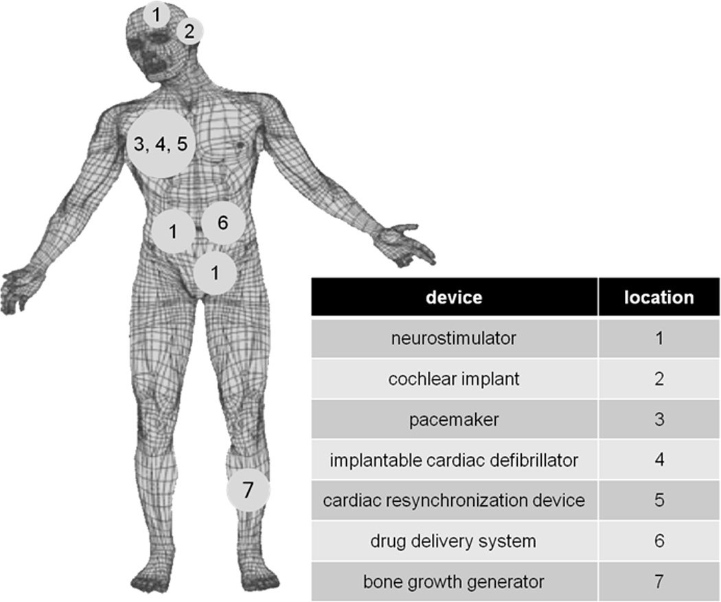
Implanted biomedical devices.
This review article is focused on battery systems that are in use to power medical implants. The battery systems are described beginning with primary batteries arranged in order of increasing current and power capability. The lithium/iodine system that functions in the microampere current range is described first followed by batteries that function in the milliampere range including lithium/manganese oxide, lithium/carbon monofluoride, and hybrid cathode systems based on silver vanadium oxide in conjunction with carbon monofluoride. Battery systems that function under ampere level currents are then discussed including cathodes based on silver vanadium oxide (SVO), manganese oxide and hybrid cathode systems based on silver vanadium oxide in conjunction with carbon monofluoride. Finally, secondary batteries that are used for implantable devices are described. The cell potential, capacity and energy density characteristics of relevant battery systems are summarized in Table 1. In each section of this article, the chemistry of the system is described along with the battery requirements of the device. Not all aspects of battery development related to implantable medical devices are available from public information sources, thus this article focuses on published information and provides a view on recent developments in the field related to batteries in use for implantable medical devices.
Table 1.
| Battery System |
Open Circuit Cell Potential |
Nominal Cell Potential |
Theoretical Gravimetric Capacity of Cathode Material (mAh/g) |
Theoretical Volumetric Capacity of Cathode Material (mAh/cm3) |
Theoretical Energy Density of Cathode Material (mWh/g) |
Energy Density of Battery (mWh/g) |
|---|---|---|---|---|---|---|
| Li/I2 | 2.8[6] | 2.8[29] | 211 | 1041 | 591 | 210–270[6] |
| Li/MnO2 | 3.3[29] | 3.0[29] | 308 | 1540 | 924 | 270 (low rate) 230 (high rate[29] |
| Li/CFx | 3.1[29] | 3.0[29] | 865 | 2335 | 2595 | 440[29] |
| Li/SVO | 3.2[29] | 3.2[29] | 315 | 1510 | 1008 | 270[29] |
| C/LiCoO2 | 4.2[91] | 3.9[91] | 155[91] | 783 | 601 | 155[91] |
2.0 Primary Batteries
2.1 Lithium/Iodine Batteries
Implantable cardiac pacemakers require a reliable power source capable of providing currents in the microampere range. The lithium/iodine-polyvinylpyridine (PVP) system, first patented in 1972,[1, 2] has been used to power these devices up through the present day.[3] Li/I2-PVP cells are the principal option for this application because of their high energy density, safety, and reliability.[4]
The basic cell reaction in a lithium iodine battery is
Li + 1/2I2 →LiI [5]
This reaction results in a cell open circuit cell potential of 2.8V.[6] The cathode material is a mixture of iodine and poly-2-vinylpyridine (PVP) in a ratio of 30/1 to 50/1, contingent upon the manufacturer’s specifications.[7] When heated to a high temperature, the materials react to produce a conductive charge transfer complex.[8] Cell construction involves adding the molten cathode material to the cell, forming a LiI layer at the anode. The LiI layer formed in situ acts as both a separator and solid electrolyte.[4] An alternative construction method of lithium/iodine cell cathodes that has also been commercially used entails pelletizing a mixture of iodine, polyvinylpyridine, and a charge transfer complex of the two materials.[9] One of the notable characteristics of the lithium/iodine cell system is that as the cell is discharged, the LiI layer continues to increase in thickness, in effect raising the impedance.[5] The impedance of the cell can be reduced by coating the lithium anode with a layer of poly-2vinylpyridine (P2VP).[10] The anode coating has been reported to result in the formation of an electrolyte liquid phase through chemical reaction of the LiI, I2 and P2VP components.[11] This liquid phase has the ability to transport Li ions and provides an improvement in lithium iodide ionic conductivity of one to two orders of magnitude higher compared to lithium iodide formed in cells with uncoated anodes.[12] The discharge process in lithium iodine cells has been characterized by impedance spectroscopy as a means of assessing the performance of new battery designs.[13]
Several characteristics of the Li/I2-PVP cell make the technology well suited for cardiac pacemakers. As the cell is discharged, because of the increasing level of impedance, the loaded cell potential decreases such that the cell potential can be used to indicate when the battery requires replacement. The discharge profile of Li/I2-PVP cells under various constant resistive loads is shown in Figure 2.[7] The microampere current levels supplied by the system are adequate for the pacemaker application.[5] The volumetric energy density of the lithium/iodine cells is near 1.0 Wh/cm3 allowing small battery size.[3] Furthermore, the Li/I layer formed through the cell reaction affords the system with a reliable electrolyte/separator.[4] Lithium/iodine-polyvinylpyridine batteries have proven to be safe over several decades in clinical use as a power source for implantable pacemakers.[7]
Figure 2.
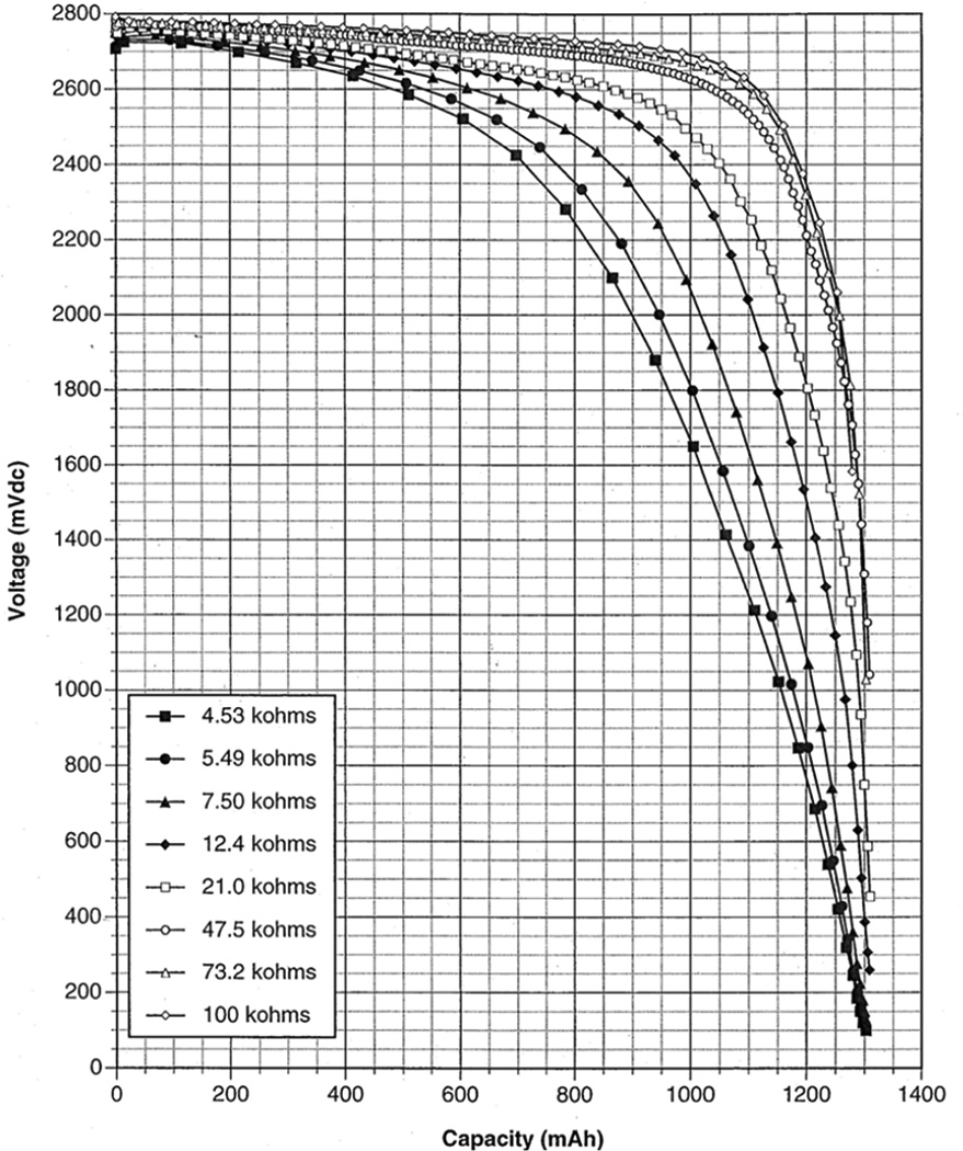
Discharge of lithium / iodine-polyvinylpyridine battery under various constant resistive loads.[7]
Recent investigations of lithium/iodine batteries include examination of using the system as a secondary battery. A solid state, rechargeable thin film Li/I2 battery has been constructed by coating a thin LiI(3-hydroxypropionitrile)2 (LiI(HPN)2) electrolyte film onto a Li anode plate, which is then reacted with I2 vapor.[14] In this system, I− anions are the principal source of ionic conductivity in the electrolyte. The system utilizes LiI(HPN)2-I2 as the cathode material and unreacted LiI(HPN)2 as a solid electrolyte. The cells display reversibility as well as improved rate performance versus Li/I2 batteries made by previously reported methods[14]. Other work has investigated electrochemically self-assembled lithium-iodine batteries where the cells consist of a polyiodide cathode, lithium anode, and LiI electrolyte.[15]
2.2 Lithium/Manganese Dioxide Batteries
Biomedical devices such as neurostimulators, drug delivery systems, and pacemakers with additional functionality require batteries capable of delivering power in the milliwatt range. The lithium/manganese dioxide primary battery, first commercialized by Ikeda et al.[16, 17] in the 1970s, is one option for these medium-rate applications. Manganese dioxide had previously seen use in zinc carbon dry cells and alkaline MnO2 cells, but the development of heat treatment allowed for the material to be used in a lithium nonaqueous system.[16–18] The lithium/manganese dioxide system has been widely used as a power source because of its high operating cell potential, high specific energy density, and excellent storage and discharge characteristics.[18]
The cell reaction in a lithium/manganese dioxide battery is
MnO2 + Li → LiMnO2 [18]
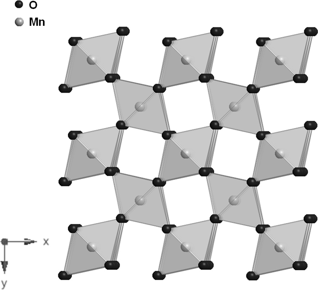
Synthetic manganese dioxides can be prepared chemically (chemically prepared MnO2, CMD) or electrochemically (electrolytic MnO2, EMD). [18–20] Heat treated EMD is used in commercialized lithium/manganese dioxide batteries.[18] Prior to heating, EMD has a mainly γ-MnO2 type crystal structure with intergrowths of a major γ-MnO2 ramsdellite phase and a β-MnO2 pyrolusite impurity. The ramsdellite is characterized by 1×2 tunnels formed by MnO6 edge sharing polyhedral (Figure 3A)[20], while the pyrolusite phase is characterized by 1×1 tunnels (Figure 3B).[21] There is general agreement that EMD contains both 1×1 and 2×2 tunnels in a hexagonally close-packed oxygen matrix.
Figure 3.
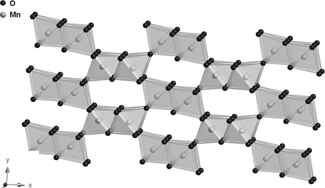
A. Structure of γ-MnO2, ramsdellite. [20]
B. Structure of β-MnO2, pyrolusite. [21]
The discharge characteristics of the Li/MnO2 system are dependent on the choice of electrolyte solution as a result of differences in electrolyte conductivity and resistance at the electrolyte-lithium electrode interface.[22] The high rate discharge behavior of cells having a 1 M LiClO4 salt concentration in various solvents containing propylene carbonate and a non-cyclic diether was investigated.[23] The electrolyte solution comprised of a 1:1 mixture of propylene carbonate and 1,2-dimethyoxyethane had the highest discharge capacity, and the discharge capacity increased with increasing conductivity of the electrolyte solution.[23] Other work has explored the impact of various lithium salts on the discharge capacity of MnO2.[22]
Various studies have investigated the mechanism of the discharge reaction in the Li/MnO2 system, which involves three distinct regions corresponding to three stages of lithium insertion into the MnO2 lattice.[24–26] The initial stage is a homogeneous insertion reaction characterized by a sloping discharge cell potential curve.[26] The second stage is a two-phase reaction indicated by a long flat region of the discharge cell potential, followed by a sloping region signifying the final homogenous lithium insertion.[4, 26]
An impedance model of a Li/MnO2 cell specifically designed for use in implantable cardiac pacemakers was developed in order to predict the battery longevity. The model allows for the cell potential drop to be calculated for a given current pulse.[27] Further work updated the model to include the impedance contribution of the interface between the cathode and current collector.[28]
The lithium manganese dioxide cell has several properties which are advantageous for its utilization as a power source for implantable applications. The relatively flat discharge profile of the system results in a stable nominal cell potential of 3.0V.[18, 26, 29] The theoretical specific energy of the cell is high at 924 mWh/g. As previously stated, the medium rate currents supplied by Li/MnO2 batteries widen the application range for this power source. Moreover, these cells have a low self-discharge rate and a high level of stability.[18]
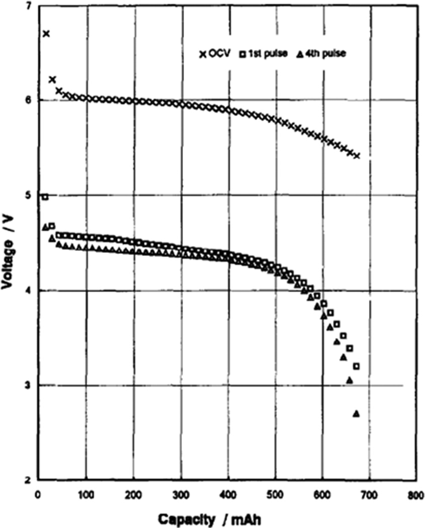
A battery using the lithium manganese dioxide system has been developed specifically for biomedical applications.[30] The design of the cell involves a central lithium anode surrounded by two cathodes in a stainless steel casing. The battery, having a volume of 10.5 cm3 and a volumetric energy density of 0.588 Wh/cm3, was able to pulse currents of up to 0.4A and attained a capacity of 2.5 Ah using the study’s discharge parameters. The pulsetrain discharge profile of this medium rate battery is shown in Figure 4.[30] The Li/MnO2 system has also been developed for high rate medical applications and will be discussed in the section on high rate batteries.
Figure 4.
Pulsatile discharge of lithium / manganese dioxide battery under background load of 600 kΩ with 4× 9 s pulses applied every 30 min. Background cell potential, pulse minimum cell potential for 1st and 4th pulses are shown.[30]
Recent work involving the lithium-manganese dioxide system centers on using it as a secondary battery.[19, 31, 32] The interest in MnO2 based cathode materials for rechargeable Li-ion batteries derives from its low cost compared to LiCoO2. An EMD/C composite material prepared by mechanical milling followed by heat treatment at 400 C has been described.[33] Other work involves ion exchange of structural protons in EMD with lithium prior to heat treatment, and results in lithium substituted, ordered MnO2 materials.[19] Of these, the most crystalline form exhibits good reversibility after multiple cycles and a discharge capacity of 210 mAh/g.
2.3 Lithium/ Carbon Monofluoride Batteries
An alternative option for implantable biomedical devices requiring current outputs in the milliampere range is the lithium/ carbon monofluoride (Li/CFx) system. Carbon monofluoride was first developed as a cathode material for lithium primary batteries in the early 1970s.[34, 35] The low self-discharge, high working cell potential and high energy density of the Li-CFx system have made it useful as a medium rate power source.[36]
Carbon monofluoride (CFx) is a solid state cathode material prepared by direct fluorination of carbon with F2 at temperatures ranging from 400 to 600 C.[37] The highly stable structure consists of sp3 hybridized carbon layers, with fluorine covalently bonded to carbon, as shown in Figure 5.[38] The carbon / fluorine ratio of the material can be varied. While higher fluorine content increases the theoretical capacity of the material, it decreases its electrical conductivity.[38, 39] Because the material is an insulator, CFx is mixed with a conductive additive during cathode preparation, along with a binder so that a cathode pellet may be pressed.[4] Cell construction includes the solid cathode, a lithium anode, and a separator between the two electrodes. The electrolyte typically used is lithium tetrafluoroborate (LiBF4) dissolved in γ-butyrolactone.[36]
Figure 5.
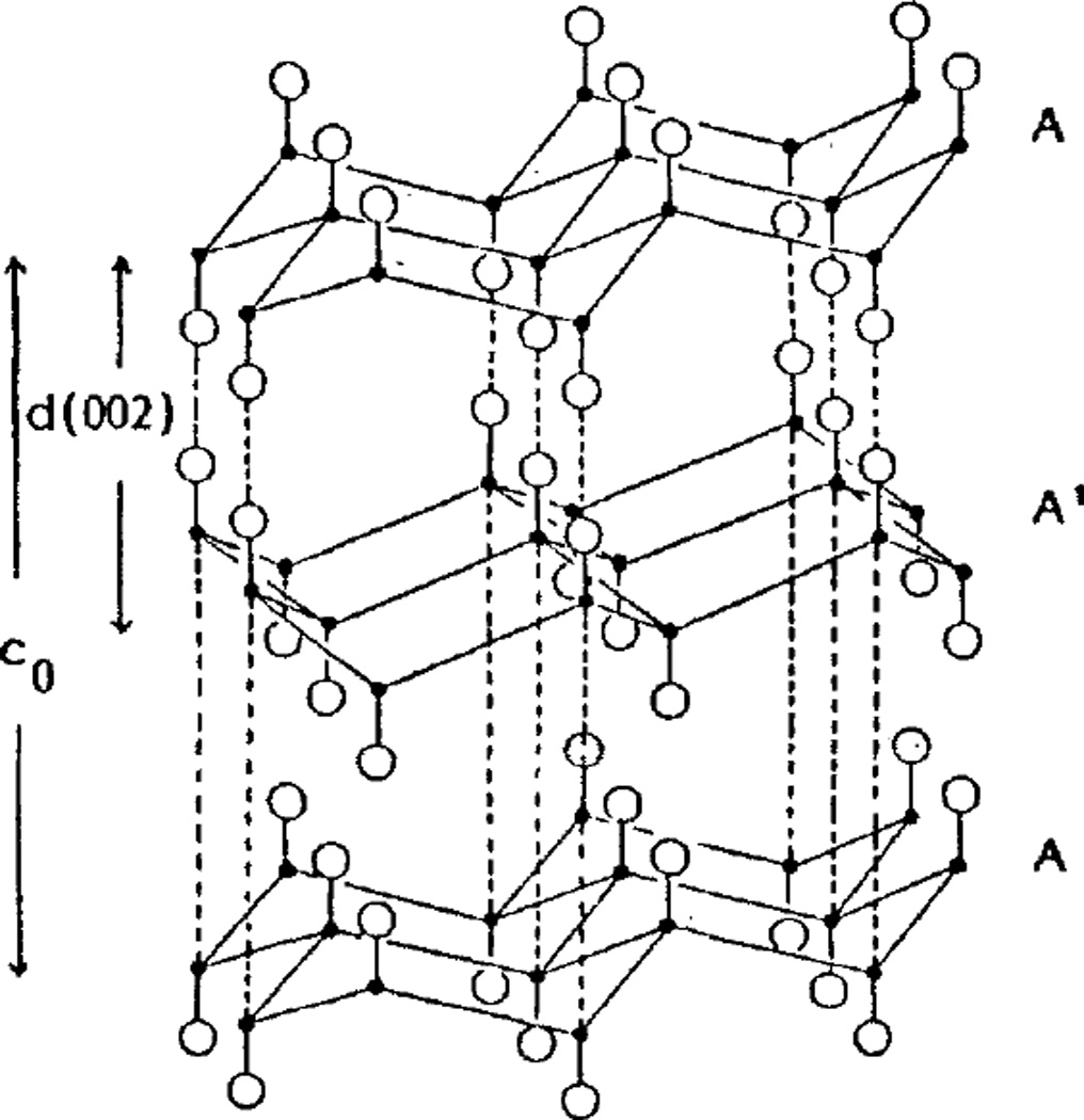
Structure of carbon monofluoride.[38]
The cell overall reaction in Li/CFx cells is:
xLi + CFx → xLiF + C [36]
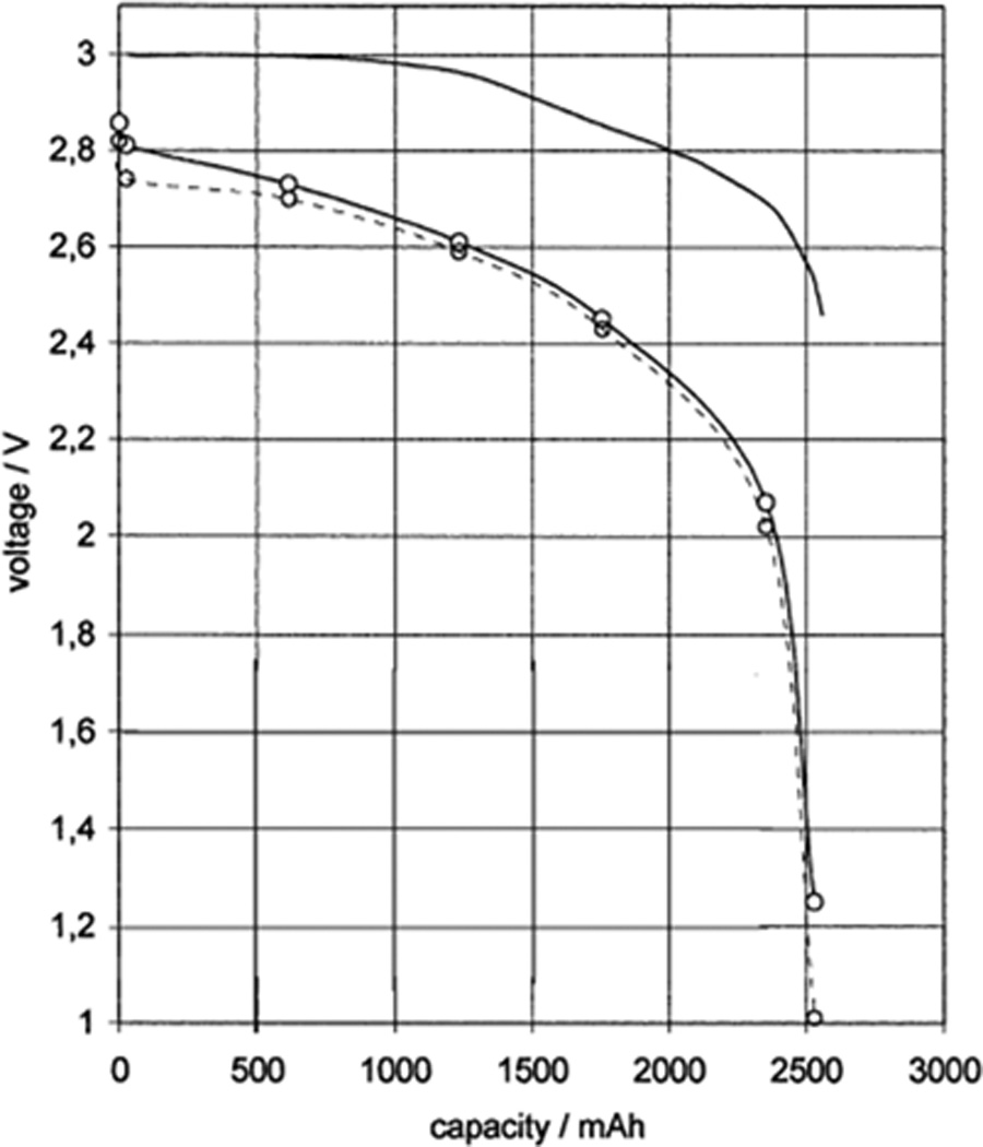
The discharge reaction has been described as proceeding by initial insertion of solvated lithium ions into the graphite fluoride layer, forming an intermediate phase consisting of carbon, fluoride, and lithium ions. [40, 41] The intermediate phase, considered to be a diffusion layer, gradually decomposes into lithium fluoride, carbon, and solvent molecules as the cell is discharged. The open circuit potential of Li-CFx cells is typically around 3.1 V, which is significantly lower than the calculated electromotive force of 4.57V for the overall reaction.[29, 42] The observed OCV differs from the calculated thermodynamic value because the electron transfer reaction in the intermediate phase determines the equilibrium cell potential.[41] Thus, the magnitude of the overpotential has been explained by solvated lithium ion transfer in the intermediate phase, and is therefore dependent on the solvent molecule size, solvation number, and interlayer spacing of the graphite fluoride cathode material.[41, 42] The thickness of the intermediate phase is maintained through discharge, keeping the overpotential constant and providing a relatively flat discharge potential.[41] The discharge profile of Li/CFx cells designed for use in medical applications is shown in Figure 6.[43]
Figure 6.
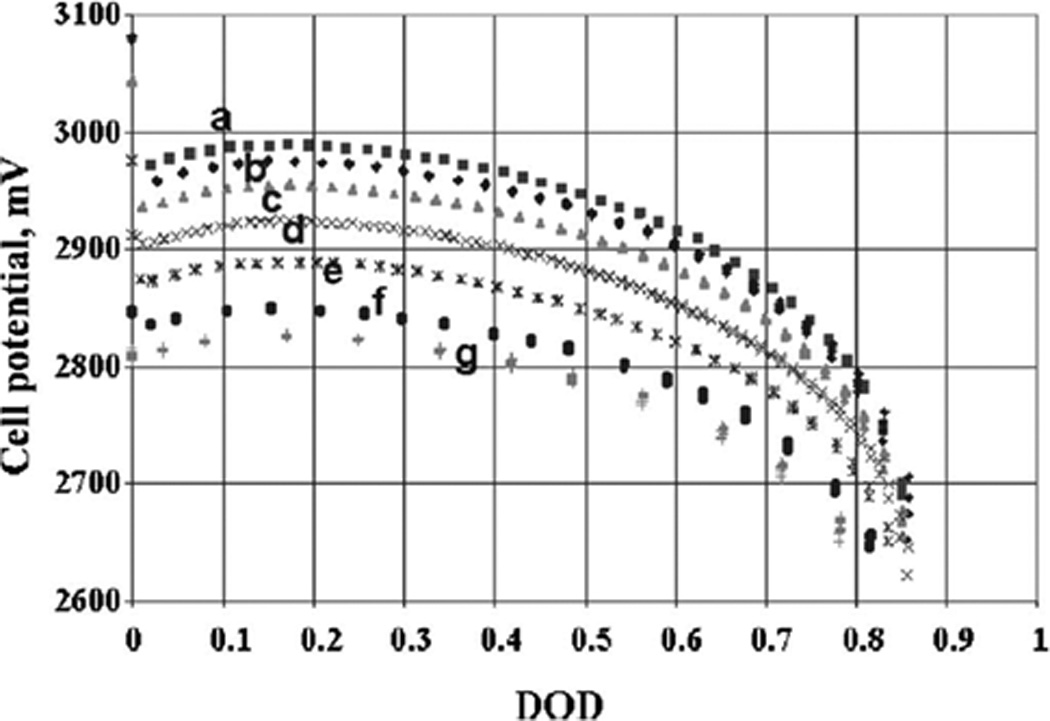
Discharge curves of lithium / carbon monofluoride batteries under constant resistances of (a) 140, (b) 100, (c) 64.9, (d) 32.4, (e) 16.5, (f) 7.5, and (g) 4.53 kΩ.[43] DOD = depth of discharge.
Researchers have proposed methods to simulate the Li-CFx system under conditions of both constant low rate discharge and periodic pulse discharge.[43, 44] Li-CFx cells were constructed and discharged over a period of 0.27 to 7.19 years. A dual intercalation model was formulated to simulate the constant discharge condition. Compiled cell data was in agreement with the behavior predicted by the model, and the system was determined to follow Tafel kinetics. For the pulse discharge condition, a zero dimensional model was used to successfully predict the experimental results.[44]
The lithium/carbon monofluoride system is attractive as a power source for implantable medical devices for a number of reasons. The discharge profile is predictable over time, allowing the battery’s end of service point to be determined electronically. The low internal impedance allows the battery to be used in medium rate applications requiring milliampere level currents. The theoretical volumetric capacity of the cathode material is high at 2335 mAh/cm3. Furthermore, the self discharge of the system is low and the cell chemistry has a history of stability and safety.[36] Batteries using Li/CFx specifically for medical devices have been described in the literature. Miniature pin-type cells using a spiral wound battery design have been developed that can produce pulse currents of up to 10 mA and have a volume of only 0.155 cm3.[45] The discharge characteristics of Li/CFx batteries designed for low rate devices have also been reported. [43, 44, 46]
Recent investigations of the lithium/ carbon monofluoride system involve optimization of cathode materials. Thermal treatment of CFx just below the decomposition temperature has been reported to increase discharge cell potential.[47] Carbothermal treatment with carbon black has also shown to increase discharge performance by increasing the reaction kinetics of the cathode.[48] Other research has investigated the use of multi-walled carbon nanotubes (MWCNTs) as an alternative conductive additive.[49]
Additional studies have focused on improving the understanding of the Li/CFx cell discharge mechanism and electrochemistry. Cathode swelling in discharged Li/CFx cells has been proposed to be due to deposition of LiF in the internal carbon surfaces of the cathode.[50] Other work has utilized dc-polarization and ac-impedance techniques to show that overall cell impedance is dominated by resistance of the cathode.[51]
2.4 Li/CFx - SVO hybrid batteries
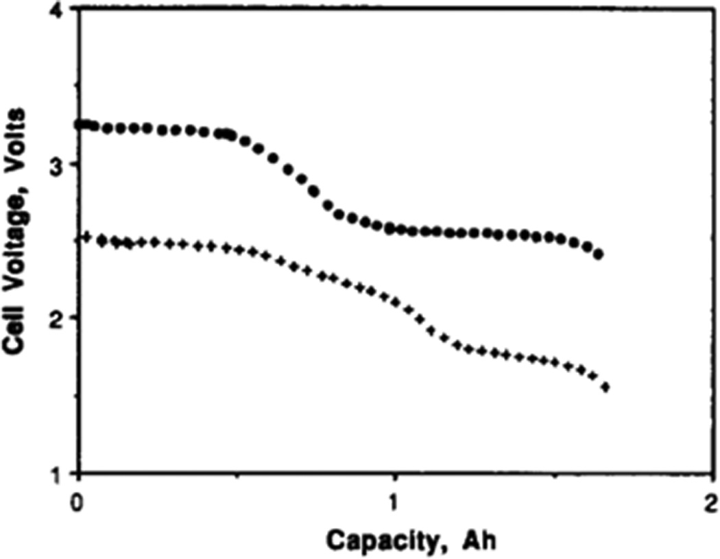
The high energy density of lithium/ carbon monofluoride system allows batteries of this type to provide the longevity needed for implantable biomedical devices requiring medium rate currents. In order to provide even higher pulse current capability than CFx alone, lithium batteries with hybrid cathodes combining CFx and silver vanadium oxide, Ag2V4O11, have been developed. [52, 53] A more detailed discussion of the lithium/ silver vanadium oxide system is located in the section on high rate batteries. In addition to improving the power density compared to cells constructed using only the Li/CFx system, these hybrid batteries offer enhanced end of service detection due to the appearance of a lower potential plateau at the end of discharge. A comparison of the cell potential profiles of a lithium / silver vanadium oxide cell and a lithium / carbon monofluoride cell is shown in Figure 7.[53]
Figure 7.
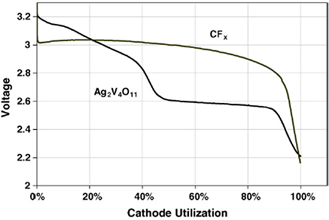
Discharge cell potential of lithium / silver vanadium oxide cell and lithium / carbon monofluoride cell at 2 µA/cm2.[53]
There are two basic designs of hybrid Li/CFx - SVO hybrid batteries described in the literature. The first utilizes a cathode consisting of physically mixed silver vanadium oxide and carbon monofluoride materials.[53] An alternative cell design using a laminated cathode [52] is able to deliver high current pulses and is included in the high rate battery section.
The discharge behavior of Li/CFx – SVO hybrid cells using the physically mixed cathode model has been described.[53] At low current rates, the SVO material is partially reduced first, followed by complete discharge of CFx , followed by reduction of the remaining SVO.[53] At higher rates, SVO is expected to provide most of the energy due to its higher current carrying capability, lowering its potential relative to CFx. The CFx then recharges the SVO so that the potential of the two materials is at equilibrium. Hybrid cells of this type have a detectable end of service point in the cell potential profile, and those optimized to deliver medium rate currents have an energy density of approximately 1 Wh/cm3. Furthermore, composition of the mixture can be adjusted to suit the application, depending on whether additional capacity or power density is required.
Physically based mathematical models of Li/CFx-SVO hybrid cathode batteries using the mixed cathode design have been described.[54–56] These models were developed using the assumptions that the cathode determines battery capacity, is kinetically limited and contributes most of the resistance. The models do not take heat generation or parasitic reactions into account, and make assumptions regarding the morphology and size of the particles. The models estimate kinetic and thermodynamic parameters from experimental data and are able to predict the discharge behavior of the hybrid batteries over a range of conditions.
2.5 High Rate Batteries – Lithium/Silver Vanadium Oxide
Implantable cardioverter defibrillators (ICDs) are medical devices designed to continuously monitor a patient’s heart and sense tachycardia (rapid heartbeat). If ventricular fibrillation is detected which cannot be addressed by pacing, a high energy shock is applied by the ICD so that heartbeat is restored to a normal rate. The high power demands of ICDs necessitate a battery which is capable of delivering high current pulses of 2–3 A in order to rapidly charge the capacitors of the device.[5] Furthermore, the battery must supply a constant low current to power the heart monitoring functions of the ICD. The battery must also be of a suitable size and remain able to deliver intermittent high current pulses throughout its lifetime while implanted in the patient. The lithium/silver vanadium oxide (Li/SVO) system meets the above requirements and is the most commonly used battery in ICDs today.
While the Li/SVO battery was initially intended for non-medical use,[57] it was the implementation of the system for implantable medical applications that fully realized its benefits and capabilities.[58] Since its initial implementation in the 1980s, numerous improvements have optimized the Li/SVO system as a high rate ICD battery,[59] including materials synthesis,[60–64] electrolyte modifications,[65] electrolyte additives,[66] and cell design.[67, 68]
The SVO cathode material, Ag2V4O11, is conventionally prepared using a solid state synthesis method.[64] SVO has a layered structure comprised of edge and corner sharing distorted VO6 octahedra, as shown in Figure 8.[69] The overall discharge reaction is:
7Li + Ag2V4O11 → 2Ag0 + Li7V4O11 [5]
Figure 8.
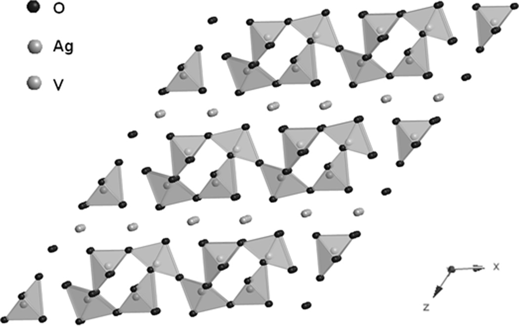
Structure of Ag2V4O11.[69]
Seven moles of lithium can be incorporated into the structure, corresponding to a theoretical specific capacity of 315 mAh/g. The volumetric capacity of cathode material is high at 1510 mAh/mL and the open circuit cell potential of Li/SVO cells is approximately 3.2 V.[29] The pulse discharge profile of Li/SVO cells, shown in Figure 9, illustrates the ability of the system to deliver high current therapy pulses for the implantable ICD application.[61]
Figure 9.
Discharge of lithium / silver vanadium oxide battery under 100 kΩ load with 4 × 2 A pulses applied every 30 days.[61]
The discharge process in the Li/SVO system has been extensively studied through characterization of the cathode material at various stages reduction.[70, 71] XRD analysis of LixAg2V4O11 discharge products, where × is the moles of Li+ intercalated into the material, indicate that the reduction of Ag+ to Ag0 occurs from 0 < × < 2.4 and is accompanied by a loss of crystallinity.[70] The reduction of silver comprises 30% of the cathode’s capacity and significantly improves the conductivity, permitting the Li/SVO system to be used in high rate applications. While some vanadium reduction occurs earlier in the discharge process, from 2.4 < × < 3.8 the discharge process is dominated by reduction of V5+ to V4+. Upon further reduction at × > 3.8, V4+ to V3+ reduction results in mixed valence materials containing vanadium at (III), (IV), and (V) oxidation states.[70] The multi-stage reduction reaction results in a stepped cell potential profile, as shown in Figure 10.[71] This characteristic cell potential profile is significant for use in the ICD application as it allows physicians to reliably predict when battery replacement will be needed.[5] Recent studies of the discharge process using nuclear magnetic resonance and x-ray absorption spectroscopy indicate that reduction of vanadium (V) initiates simultaneous to silver reduction in the initial discharge step.[72] Other work has indicated that the rate capability of the system is limited by diffusion transport during lithium intercalation.[73]
Figure 10.
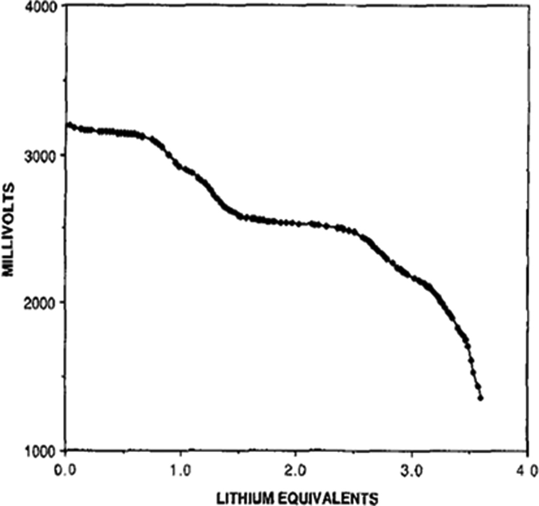
Discharge of lithium / silver vanadium oxide cells at a two-year rate.[71]
Li/SVO cells employ an electrolyte consisting of propylene carbonate and dimethoxyethane with a dissolved lithium salt.[5] Batteries may be constructed using multi-plate cathode design, as shown in Figure 11, which connects numerous cathodes in parallel to raise the current output of the cell.[61] A second design, shown in Figure 12, features of strips of anode and cathode wound together in a flattened coil.[74] Mathematical models of these cells have been developed to account for changes in cell resistance during discharge.[75] Experimental data indicates that resistance increases due to concentration polarization and is dependent on discharge rate.
Figure 11.
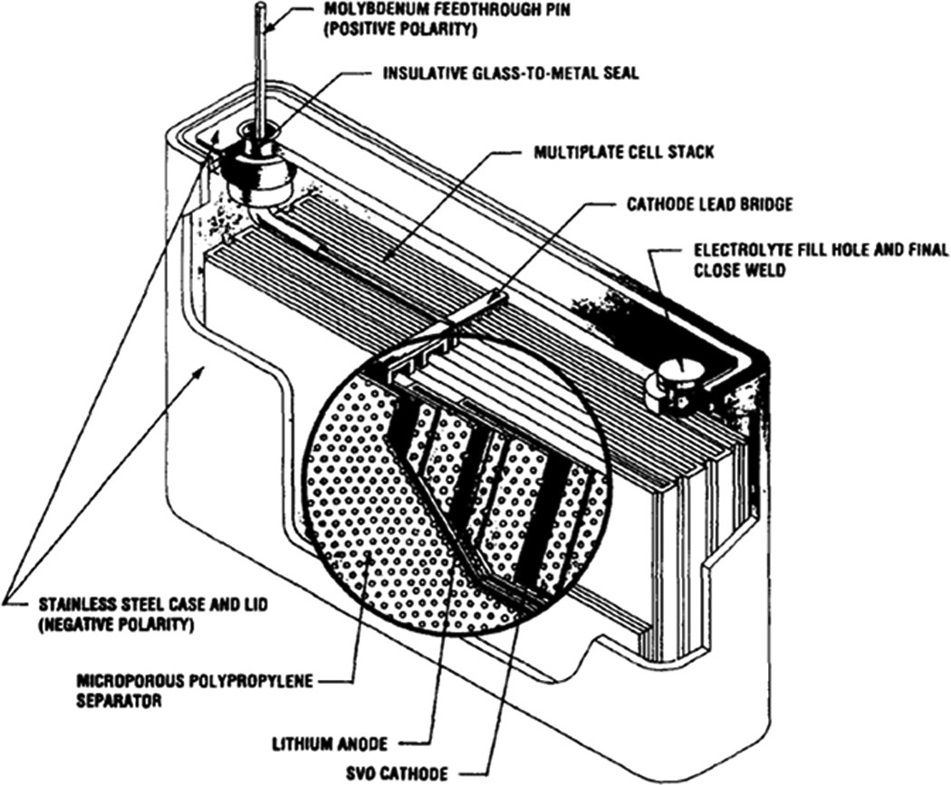
Schematic of multiplate implantable cardiac defibrillator battery.[61]
Figure 12.
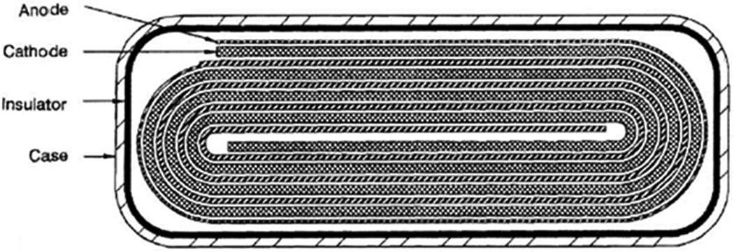
Schematic of coiled configuration implantable cardiac defibrillator battery.[74]
Recent investigations involving the Li/SVO system have focused on the optimization of the active cathode material. A recently reviewed approach to enhancing performance is the development of SVO nanomaterials.[76] It is reasoned that decreasing particle size will result in higher diffusion rates of lithium during the intercalation process. Furthermore, the unique electronic properties of nano-sized materials may lead to increased capacities and higher cell potentials. A molten salt synthesis method has been developed to prepare nanocrystalline Ag2V4O11.[77] Materials synthesized through this process at 300°C are capable of delivering a discharge capacity of 269 mAh/g to a cutoff cell potential of 2 V, notably higher than the 210 mAh/g delivered by bulk SVO material.[77] The behavior of nanocrystalline SVO particles has also been described in comparison to SVO synthesized by the conventional solid state synthesis.[78, 79] Electrochemical testing indicates that the particles are able to deliver a gravimetric capacity of 320 mAh/g at C and 250 mAh/g at 5C to a 1.5 V cutoff.
The electrochemical performance of Ag2V4O11 nanowires synthesized using a low temperature hydrothermal method has been reported.[80] When these nanowires were used as the cathode material in two electrode cells, the initial open circuit cell potential was 3.52 V, and the discharge capacity was 366 mAh g−1 to a 1.5 V cutoff. By comparison, Ag2V4O11 bulk material prepared using the conventional solid state synthesis method had an open circuit cell potential which was 200 mV lower, and was only able to deliver a discharge capacity of 319 mAh/g.
Recently, silver vanadium phosphorous oxides (AgwVxPyOz) have been proposed as a new material class suitable for potential use in high rate applications such as ICDs. This material class was deliberately selected based on the desire to obtain the chemical stability observed in other phosphate cathode materials coupled with high capacity due to multiple electron equivalents per formula unit and the opportunity for in situ generation of a conductive cathode matrix upon initial reduction of Ag+ to Ag0, reminiscent of SVO. The first example in this material family, Ag2VO2PO4, showed suitability for high rate use, yielding 205 mAh/g to 2.0 V and 270 mAh/g to 1.5 V under constant current discharge, and supporting 50 mA/cm2 pulses above 1.5 V.[81, 82] Further investigation of the reduction mechanism revealed a 15000 fold increase in cathode conductivity with initial discharge,[83] supporting the proposed electrochemical reduction-displacement mechanism.[84, 85] A second member of the silver vanadium phosphorous oxide material family, Ag0.48VOPO4, was recently reported, exhibiting high cell potential on discharge and a characteristic multi-plateau cell potential profile, both desirable properties for ICD use.[86]
2.6 High Rate Batteries – Lithium/Manganese Dioxide
The Li/MnO2 system is an alternative to Li/SVO for powering implantable defibrillators. Cells have been developed which are able to meet the power source requirements for ICDs described in the previous section. Manganese dioxide has an acceptable energy density and the system is capable of delivering high current pulses.[87] Furthermore, the resistance of Li/MnO2 cells does not increase until the end of discharge, so performance at high rates does not diminish with time.
Li/MnO2 batteries suitable for the ICD application have been developed where the cathode consists of manganese dioxide mixed with chromium oxide and lead oxides.[88] The addition of these compounds results in a discharge profile which indicates when the remaining capacity is low and the battery needs to be replaced.
A high rate Li/MnO2 battery based on a double cell concept has also been produced.[89] The design incorporates two cathode-limited cells, connected in series by the battery casing in order to reduce volume. The use of two cells improves the high rate performance relative to the single cell design. The pulse discharge profile of the double cell design is shown in Figure 13.[89]
Figure 13.
Discharge of lithium / manganese dioxide double cell battery with 4 × 1.4 A pulses applied every 30 minutes.[89]
High rate Li/MnO2 double cell batteries have been improved by integrating them into a hybrid system.[90] Compared to the double cell only battery, the hybrid system has a larger low rate capacity at a smaller volume, with only a minor loss of pulse-power capability. The discharge behavior of Li/MnO2 cells designed for ICD devices has been predicted through the use of mathematical models.[87] The experimental discharge curves were modeled using a function which accounts for excess free energy arising from lithium ion – cathode interactions.
2.7 High Rate Batteries - Li/CFx - SVO hybrid
Li/CFx –SVO hybrid cells using a novel electrode design are reported which are able to deliver high current pulses, also enabling their use in ICDs.[52] The cathode consists of CFx sandwiched between two layers of SVO material, as shown in Figure 14.[52]
Figure 14.
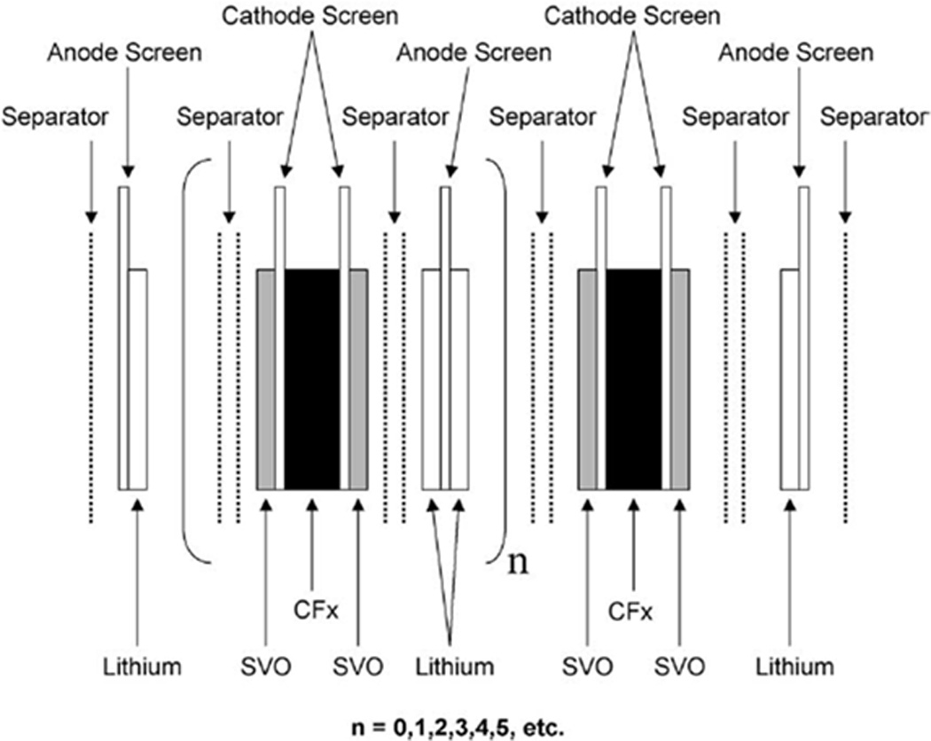
Schematic of battery design for dual-chemistry cathode system.[52]
The discharge profile of the hybrid cells exhibits plateaus at 3.2V, 2.8V, and 2.6V, which correspond to the respective discharge of SVO, CFx, and SVO.[52] After initial reduction of SVO, most of the energy for low rate currents is provided by CFx. However, if the cell is pulsed under heavy loads, SVO is preferentially discharged, and the resulting potential of SVO is then less than that of CFx. The stepped cell potential profile of these dual cathode cells indicates when the battery needs to be replaced. Pulse discharge profiles of these cells at various current densities are shown in Figure 15.[52]
Figure 15.
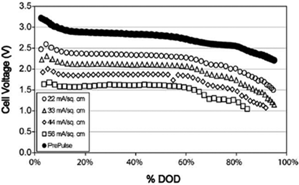
Discharge profile for pulsatile discharge test of dual-chemistry cathode cell with 1 pulse applied every 23 hours at alternating currents. Pulse minimum cell potentials are shown.[52]
3.0 Secondary Batteries
3.1 Li-ion Batteries - Milliwatt Power Levels
Some applications having high power usage rates can benefit from the use of rechargeable batteries in order to improve implant lifetime and reduce size. Secondary power sources for implantable medical devices must satisfy the same general requirements as primary batteries, including safety, reliability, high energy density, and low self-discharge. Neurostimulators, which operate in the milliwatt power range, are one type of device for which secondary batteries have been developed. These cells operate using lithium-ion technology.
Li-ion cells typically consist of a carbonaceous anode and a metal oxide cathode, with both electrode materials having the ability to intercalate lithium ions reversibly.[4] Cells are constructed using a discharged cathode material containing the source of lithium ions for the cell. During initial charge, the lithium from the cathode is extracted and inserted into the anode. The reverse process occurs during discharge. Common cathode materials include nickel, manganese, and cobalt based oxides. Lithium cobalt oxide (LiCoO2) is most often used and has a gravimetric capacity of 155 mAh/g.[91] The structure of LiCoO2 is characterized by layers alternating layers of Li and Co oxide, as shown in Figure 16.[92]
Figure 16.
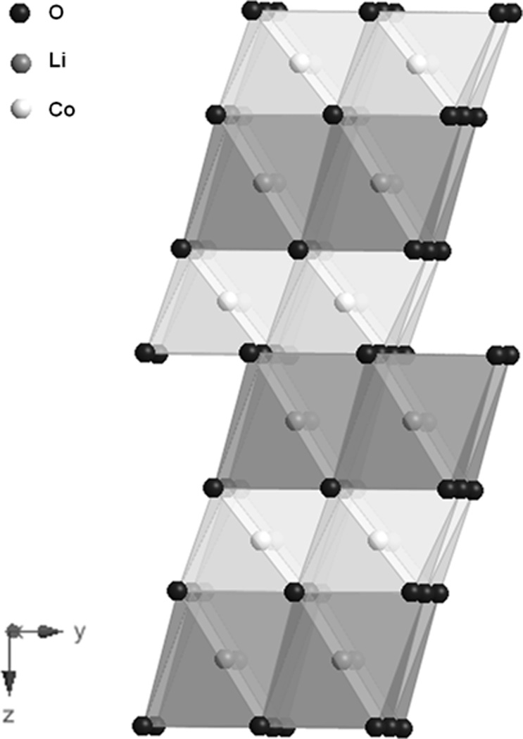
Structure of LiCoO2..[92]
Safety considerations are especially significant in implantable medical applications. Overcharging and short circuit conditions present the possibility of excess heating and cell rupture.[93, 94] Prismatic Li-ion cells utilizing LiCoO2 cathodes and graphite anodes were tested to determine the effects of overcharge rate on internal cell temperature and hermeticity. Short circuit testing increased the temperature of the cells, which remained sealed.[93] However, the study determined that at charging currents greater than C/5, the cells may rupture.
The performance of Li-ion cells developed specifically for biomedical applications has been described in the literature and studies of their performance have been conducted.[95, 96] Cells with capacities of 200 mAh were cycled at 37°C to various depths of discharge. Results indicated that after 1000 cycles, the capacity retention using the 80% depth of discharge condition was 98%.[95] A study of the solvent disproportion mechanism in lithium ion cells was also reported, providing an opportunity to develop a more stable electrolyte.[97] Spirally wound miniature pin-type batteries utilizing a LiNiCoAlO2 cathode have been developed. Cycle life testing indicates that the capacity retention is over 80% after 500 cycles.[45] These batteries exemplify the opportunity presented by Li-ion technology to engineer extremely small volume medical batteries with a rechargeable capacity.
4.0 Conclusions
A variety of battery systems has been developed that provide years of service for implantable medical devices. The primary systems utilize lithium metal anodes with cathode systems including iodine, manganese oxide, carbon monofluoride, silver vanadium oxide and hybrid cathodes using both carbon monofluoride and silver vanadium oxide. This range of batteries provides the appropriate power levels as demanded by a specific medical device varying from microampere to ampere level currents. Secondary batteries based on lithium ion chemistry have also been developed for medical applications where the batteries are charged while remaining implanted. While the performance requirements and thus the battery power delivery vary, some general characteristics are common for all batteries used in medical devices. These include high reliability and volumetric energy density, long service life, state of discharge indication, and safety during implant and in use. Successful development and implementation of these battery types has helped enable implanted biomedical devices and their treatment of human disease.
Acknowledgements
The authors acknowledge support by the National Institutes of Health under Grant 1R01HL093044-01A1 from the National Heart, Lung, and Blood Institute.
References
- 1.Schneider AA, Moser JR. Primary Cells and iodine-containing cathodes therefor. 3674562. US Patent. 1972 U.S.
- 2.Moser JR. Solid State lithium iodine primary battery. 36660163. US Patent. 1972 US.
- 3.Holmes CF. Journal of Power Sources. 1997;65:xv. [Google Scholar]
- 4.Brodd RJ, Bullock KR, Leising RA, Middaugh RL, Miller JR, Takeuchi E. Journal of the Electrochemical Society. 2004;151:K1. [Google Scholar]
- 5.Takeuchi ES, Leising RA. MRS Bull. 2002;27:624. [Google Scholar]
- 6.Owens BB, Skarstad PM, Untereker DF, Passerini S. In: Solid-electrolyte Batteries. Linden D, Reddy TB, editors. McGraw-Hill: Handbook of Batteries; 2002. [Google Scholar]
- 7.Holmes CF. ECS Transactions. 2007;6:1. [Google Scholar]
- 8.Gutmann F, Hermann AM, Rembaum A. Journal of the Electrochemical Society. 1967;114:323. [Google Scholar]
- 9.Schneider AA, Bowser GC, Foxwell LH. Lithium Iodine Primary Cells Having Novel Pelletized Depolarizer. 4148975. Patent. 1979 U.S.
- 10.Greatbatch W, Mead RT, Rudolph F. Lithium-Iodine Battery having Coated Anode. 3957533. U.S. Patent. 1976 U.S.
- 11.Phipps JB, Hayes TG, Skarstad PM, Untereker DF. Solid State Ionics. 1986;18–19:1073. [Google Scholar]
- 12.Holmes CF. Lithium/Halogen Batteries. In: Owens BB, editor. Batteries for Implantable Biomedical Devices. New York: Plenum Press; 1986. p. 133. [Google Scholar]
- 13.Schmidt CL, Skarstad PM. Journal of Power Sources. 1997;65:121. [Google Scholar]
- 14.Liu F-C, Liu W-M, Zhan M-H, Fu Z-W, Li H. Energy & Environmental Science. 2011;4:1261. [Google Scholar]
- 15.Weinstein L, Yourey W, Gural J, Amatucci GG. Journal of the Electrochemical Society. 2008;155:A590. [Google Scholar]
- 16.Ikeda H, Saito T, Tamura H. Denki Kagaku oyobi Kogyo Butsuri Kagaku. 1977;45:314. [Google Scholar]
- 17.Ikeda K, Hara M, Ikukawa K. Cathode for nonaqueous-electrolyte batteries, 1976-118327, 53042325, Japan. 1978 [Google Scholar]
- 18.Nishio K. Primary Batteries - Nonaqueous systems | Lithium-Manganese Dioxide. In: Jurgen G, editor. Encyclopedia of Electrochemical Power Sources. Amsterdam: Elsevier; 2009. p. 83. [Google Scholar]
- 19.Bowden W, Bofinger T, Zhang F, Iltchev N, Sirotina R, Paik Y, Chen H, Grey C, Hackney S. Journal of Power Sources. 2007;165:609. [Google Scholar]
- 20.Kondrashev YD, Zaslavskii AI. Izvestiya Akademii Nauk SSSR, Seriya Fizicheskaya. 1951;15:179. [Google Scholar]
- 21.Baur WH. Acta Crystallographica, Section B: Structural Crystallography and Crystal Chemistry. 1976;B32:2200. [Google Scholar]
- 22.Kim H-S, Kim H-J, Cho W-I, Cho B-W, Ju J-B. Journal of Power Sources. 2002;112:660. [Google Scholar]
- 23.Nishio K, Yoshimura S, Saito T. Journal of Power Sources. 1995;55:115. [Google Scholar]
- 24.Pistoia G. Journal of the Electrochemical Society. 1982;129:1861. [Google Scholar]
- 25.Ohzuku T, Kitagawa M, Hirai T. Journal of the Electrochemical Society. 1989;136:3169. [Google Scholar]
- 26.Nardi JC. Journal of the Electrochemical Society. 1985;132:1787. [Google Scholar]
- 27.Merritt DR, Schmidt CL. Proceedings - Electrochemical Society. 1993:138. [Google Scholar]
- 28.Merritt DR, Schmidt CL. Proceedings - Electrochemical Society. 1994;94-4:169. [Google Scholar]
- 29.Linden D, Reddy TB. In: Lithium batteries. Linden D, Reddy TB, editors. McGraw-Hill: Handbook of Batteries; 2002. [Google Scholar]
- 30.Drews J, Fehrmann G, Staub R, Wolf R. Journal of Power Sources. 2001;97–98:747. [Google Scholar]
- 31.Nagao M, Pitteloud C, Kamiyama T, Otomo T, Itoh K, Fukunaga T, Kanno R. Journal of the Electrochemical Society. 2005;152:E230. [Google Scholar]
- 32.Johnson CS. Journal of Power Sources. 2007;165:559. [Google Scholar]
- 33.Lee J, Lee J-M, Yoon S, Kim S-O, Sohn J-S, Rhee K-I, Sohn H-J. Journal of Power Sources. 2008;183:325. [Google Scholar]
- 34.Watanabe K, Fukuda M. Primary cell for electric batteries. U.S. Patent No. 3536532. 1970
- 35.Watanabe K, Fukuda M. High energy density battery. U.S. Patent Number 3700502, U.S. 1972
- 36.Greatbatch W, Holmes CF, Takeuchi ES, Ebel SJ. Pacing and clinical electrophysiology : PACE. 1996;19:1836. doi: 10.1111/j.1540-8159.1996.tb03236.x. [DOI] [PubMed] [Google Scholar]
- 37.Amatucci GG, Pereira N. Journal of Fluorine Chemistry. 2007;128:243. [Google Scholar]
- 38.Nakajima T, Hagiwara R, Moriya K, Watanabe N. Journal of the Electrochemical Society. 1986;133:1761. [Google Scholar]
- 39.Nakajima T, Mabuchi A, Hagiwara R, Watanabe N, Nakamura F. Journal of the Electrochemical Society. 1988;135:273. [Google Scholar]
- 40.Touhara H, Fujimoto H, Watanabe N, Tressaud A. Solid State Ionics. 1984;14:163. [Google Scholar]
- 41.Watanabe N, Nakajima T, Hagiwara R. Journal of Power Sources. 1987;20:87. [Google Scholar]
- 42.Hagiwara R, Nakajima T, Watanabe N. Journal of the Electrochemical Society. 1988;135:2128. [Google Scholar]
- 43.Davis S, Takeuchi ES, Tiedemann W, Newman J. Journal of the Electrochemical Society. 2007;154:A477. [Google Scholar]
- 44.Davis S, Takeuchi ES, Tiedemann W, Newman J. Journal of the Electrochemical Society. 2007;155:A24. [Google Scholar]
- 45.Nagata M, Saraswat A, Nakahara H, Yumoto H, Skinlo DM, Takeya K, Tsukamoto H. Journal of Power Sources. 2005;146:762. [Google Scholar]
- 46.Zhu HJ, Gavril M, Feng L, Karpinet D. ECS Transactions. 2008;11:11. [Google Scholar]
- 47.Zhang SS, Foster D, Read J. Journal of Power Sources. 2009;188:601. [Google Scholar]
- 48.Zhang SS, Foster D, Read J. Journal of Power Sources. 2009;191:648. [Google Scholar]
- 49.Li Y, Chen Y, Feng W, Ding F, Liu X. Journal of Power Sources. 2011;196:2246. [Google Scholar]
- 50.Read J, Collins E, Piekarski B, Zhang S. Journal of the Electrochemical Society. 2011;158:A504. [Google Scholar]
- 51.Zhang SS, Foster D, Wolfenstine J, Read J. Journal of Power Sources. 2009;187:233. [Google Scholar]
- 52.Gan H, Rubino RS, Takeuchi ES. Journal of Power Sources. 2005;146:101. [Google Scholar]
- 53.Chen K, Merritt DR, Howard WG, Schmidt CL, Skarstad PM. Journal of Power Sources. 2006;162:837. [Google Scholar]
- 54.Gomadam PM, Merritt DR, Scott ER, Schmidt CL, Skarstad PM, Weidner JW. ECS Transactions. 2007;3:45. [Google Scholar]
- 55.Gomadam PM, Merritt DR, Scott ER, Schmidt CL, Skarstad PM, Weidner JW. Journal of the Electrochemical Society. 2007;154:A1058. [Google Scholar]
- 56.Gomadam PM, Merritt DR, Scott ER, Schmidt CL, Weidner JW. ECS Transactions. 2008;11:1. [Google Scholar]
- 57.Liang CC, Bolster ME, Murphy RM. Metal oxide composite cathode material for high energy density batteries. 4310609. US patent. 1982 US.
- 58.Takeuchi ES, Piliero P. Journal of Power Sources. 1987;21:133. [Google Scholar]
- 59.Takeuchi KJ, Marschilok AC, Davis SM, Leising RA, Takeuchi ES. Coordination Chemistry Reviews. 2001;219–221:283. [Google Scholar]
- 60.Leising RA, Takeuchi ES. Chemistry of Materials. 1994;6:489. [Google Scholar]
- 61.Takeuchi ES. Journal of Power Sources. 1995;54:115. [Google Scholar]
- 62.Takeuchi KJ, Leising RA, Palazzo MJ, Marschilok AC, Takeuchi ES. Journal of Power Sources. 2003;119–121:973. [Google Scholar]
- 63.Takeuchi ES, Marschilok AC, Leising RA, Takeuchi KJ. J. Power Sources. 2007;174:552. [Google Scholar]
- 64.Leising RA, Takeuchi ES. Chemistry of Materials. 1993;5:738. [Google Scholar]
- 65.Gan H, Takeuchi ES. Organic carbonate additives for nonaqueous electrolyte in alkali metal electrochemical cells. US5753389. 1998 U.S.
- 66.Gan H, Takeuchi ES. Ternary solvent nonaqueous organic electrolyte for alkali metal electrochemical cells. 5776635. U.S. Patent. 1998 U.S.
- 67.Keister P, Mead R, Muffaletto B, Takeuchi ES, Ebel SJ, Zelinsky M, Greenwood J. Nonaqueous lithium battery. 4830940. U.S. Patent. 1989 U.S.
- 68.Takeuchi ES, Post CJ. Electrochemical cell with improved efficiency serpentine electrode. 5147737. U.S. Patent. 1992 U.S.
- 69.Onoda M, Kanbe K. Journal of Physics: Condensed Matter. 2001;13:6675. [Google Scholar]
- 70.Leising RA, Thiebolt WC, III, Takeuchi ES. Inorganic Chemistry. 1994;33:5733. [Google Scholar]
- 71.Takeuchi ES, Thiebolt WC., III Journal of the Electrochemical Society. 1988;135:2691. [Google Scholar]
- 72.Leifer ND, Colon A, Martocci K, Greenbaum SG, Alamgir FM, Reddy TB, Gleason NR, Leising RA, Takeuchi ES. Journal of the Electrochemical Society. 2007;154:A500. [Google Scholar]
- 73.Ramasamy RP, Feger C, Strange T, Popov BN. Journal of Applied Electrochemistry. 2006;36:487. [Google Scholar]
- 74.Crespi AM, Somdahl SK, Schmidt CL, Skarstad PM. Journal of Power Sources. 2001;96:33. [Google Scholar]
- 75.Crespi A, Schmidt C, Norton J, Chen K, Skarstad P. Journal of the Electrochemical Society. 2001;148:A30. [Google Scholar]
- 76.Cheng F, Chen J. Journal of Materials Chemistry. 2011;21:9841. [Google Scholar]
- 77.Cao X, Xie L, Zhan H, Zhou Y. Inorganic Materials. 2008;44:886. [Google Scholar]
- 78.Sauvage F, Bodenez V, Vezin H, Morcrette M, Tarascon JM, Poeppelmeier KR. Journal of Power Sources. 2010;195:1195. [Google Scholar]
- 79.Sauvage F, Bodenez V, Tarascon J-M, Poeppelmeier KR. Journal of the American Chemical Society. 2010;132:6778. doi: 10.1021/ja1009713. [DOI] [PubMed] [Google Scholar]
- 80.Zhang S, Li W, Li C, Chen J. Journal of Physical Chemistry B. 2006;110:24855. doi: 10.1021/jp065478p. [DOI] [PubMed] [Google Scholar]
- 81.Marschilok AC, Takeuchi KJ, Takeuchi ES. Electrochem. Solid-State Lett. 2008;12:A5. [Google Scholar]
- 82.Kim YJ, Marschilok AC, Takeuchi KJ, Takeuchi ES. J. Power Sources. 2011;196:6781. doi: 10.1016/j.jpowsour.2010.10.054. [DOI] [PMC free article] [PubMed] [Google Scholar]
- 83.Takeuchi ES, Marschilok AC, Tanzil K, Kozarsky ES, Zhu S, Takeuchi KJ. Chemistry of Materials. 2009;21:4934. doi: 10.1021/cm902102k. [DOI] [PMC free article] [PubMed] [Google Scholar]
- 84.Marschilok AC, Kozarsky ES, Tanzil K, Zhu S, Takeuchi KJ, Takeuchi ES. Journal of Power Sources. 2010;195:6839. doi: 10.1016/j.jpowsour.2010.04.033. [DOI] [PMC free article] [PubMed] [Google Scholar]
- 85.Patridge CJ, Jaye C, Abtew TA, Ravel B, Fischer DA, Marschilok AC, Zhang P, Takeuchi KJ, Takeuchi ES, Banerjee S. Journal of Physical Chemistry C. 2011;115:14437. [Google Scholar]
- 86.Kim YJ, Lee C-Y, Marschilok AC, Takeuchi KJ, Takeuchi ES. Journal of Power Sources. 2011;196:3325. doi: 10.1016/j.jpowsour.2010.11.144. [DOI] [PMC free article] [PubMed] [Google Scholar]
- 87.Root MJ. Journal of Power Sources. 2010;195:5089. doi: 10.1016/j.jpowsour.2010.04.033. [DOI] [PMC free article] [PubMed] [Google Scholar]
- 88.Fehrmann G, Frommel R, Wolf R. Galvanic Cell having improved cathode. 5587258. US Patent. 1996 U.S.
- 89.Drews J, Wolf R, Fehrmann G, Staub R. Journal of Power Sources. 1997;65:129. [Google Scholar]
- 90.Drews J, Wolf R, Fehrmann G, Staub R. Journal of Power Sources. 1999;80:107. [Google Scholar]
- 91.Ehrlich GM. Lithium-ion batteries. In: Linden D, Reddy TB, editors. Handbook of Batteries. McGraw-Hill: 2002. [Google Scholar]
- 92.Orman HJ, Wiseman PJ. Acta Crystallogr., Sect. C: Cryst. Struct. Commun. 1984;C40:12. [Google Scholar]
- 93.Leising RA, Palazzo MJ, Takeuchi ES, Takeuchi KJ. Journal of the Electrochemical Society. 2001;148:A838. [Google Scholar]
- 94.Leising RA, Palazzo MJ, Takeuchi ES, Takeuchi KJ. Journal of Power Sources. 2001;97–98:681. [Google Scholar]
- 95.Dodd J, Kishiyama C, Nagata M, Nakahara H, Yumoto H, Tsukamoto H. Proceedings - Electrochemical Society. 2004;2003–28:360. [Google Scholar]
- 96.Rubino RS, Gan H, Takeuchi ES. Journal of the Electrochemical Society. 2001;148:A1029. [Google Scholar]
- 97.Takeuchi ES, Gan H, Palazzo M, Leising RA, Davis SM. Journal of the Electrochemical Society. 1997;144:1944. [Google Scholar]