

Abstract
Anthropometric measurements, such as the circumferences of the hip, arm, leg and waist, waist-to-hip ratio, and body mass index, are of high significance in obesity and fitness evaluation. In this paper, we present a home based imaging system capable of conducting automatic anthropometric measurements. Body images are acquired at different angles using a home camera and a simple rotating disk. Advanced image processing algorithms are utilized for 3D body surface reconstruction. A coarse body shape model is first established from segmented body silhouettes. Then, this model is refined through an inter-image consistency maximization process based on an energy function. Our experimental results using both a mannequin surrogate and a real human body validate the feasibility of proposed system.
I. INTRODUCTION
Anthropometric measurements, such as the circumferences of hip, waist, leg, and arm, waist-to-hip ratio, and body mass index, are important metrics for evaluation of obesity and fitness. These measurements are the interests of not only primary care physicians, but also the general public for self-maintenance of health. Traditionally, these metrics are measured using a stretch resistant tape wrapped snugly around the body, where the tape line must be leveled (e.g., in parallel to the floor surface) [1]. Although the measurements are relatively simple, this traditional method has several drawbacks: 1) the accuracy of measurement is highly dependent on the location of the tape in the body; 2) the tightness of placement is difficult to control consistently; 3) the type of the tape affects the measurement results; 4) a person must conduct measurements for another person whose clothes are removed, resulting major privacy concerns for some people; and 5) the measurements are time consuming. Therefore, a private, rapid, accurate, convenient, and machine conducted measurement system in both clinics and homes is highly desirable.
Reconstructing a 3D human body surface for anthropometric measurements is a challenging task due to the following problems: 1) most parts of the human body lack identifiable texture contents for the algorithm to establish matches of pixel pairs (called dense correspondences) between images in different views; 2) body sways of the subject are inevitable during the image acquisition process, causing errors in 3D surface reconstruction; 3) most existing algorithms are based on an assumption that the object (here the human body) being reconstructed is rigid [2], which is invalid in our case. In order to solve these problems, laser scanners and structured light technology have been used to reconstruct objects without sufficient identifiable textures [3, 5]. However, laser and structured light scanning often make the person feel uncomfortable during the data acquisition process. In [8], a set of high resolution cameras are used to acquire small skin details such as pores, freckles and wrinkles as landscape markers in images to produce dense correspondences. However, their work only focuses on face reconstruction and the cost of their system is a concern since more than fourteen high-resolution cameras are utilized, not suitable for home settings. In order to detect body sways and eliminate its effect quantitatively, a camera network is utilized with a specific algorithm design [4, 6, 7]. Again, this system is expensive and its flexibility is lacking.
In this paper, we propose a feasible, efficient and low-cost system for 3D reconstruction of the human body surface. Our system uses a single high resolution digital camera, which is already available at many homes, and a simple rotating disk to conduct self-measurements of anthropometric metrics at private home or clinic settings. In the following sections, we describe our system design, data processing algorithms, and experimental results using both the mannequin and human subject data to validate the performance of our system.
II. MULTI-VIEW IMAGE ACQUISITION OF HUMAN BODY
The proposed system consists of two major components: a rotating disk as the standing base of a given subject, and a high resolution digital camera to capture a set of images of the body. It is desirable to allow adjustment of the lighting condition to reduce reflection artifacts on the human skin. Fig. 1(a) shows a sketch of the system configuration. Once the subject stands on the disk, it starts rotating slowly as the camera takes pictures repeatedly. The rate of picture taking is preset to one image per α degree of rotation. When α is small, more images are acquired. As a result, the modeling is more precise but at a cost of more complex computation. Therefore, in practice, we use α = 20° to trade off these two conflicting factors. Fig. 1(b) and (c) show two examples of the acquired raw images.
Fig. 1.
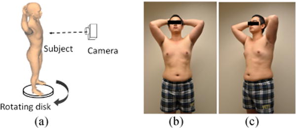
(a) Sketch of the system configuration; (b) and (c): Two of the acquired raw images.
III. IMAGE-BASED 3D MODELING AND MEASUREMENT
A. Overview of Computational Procedure
First, our system performs a calibration process using the structure from motion technique for geometric matching among different imaging positions (section B). Then, we build a coarse 3D triangular mesh of the human body by a visual hull approximation (section C). Since the coarse mesh contains considerable errors, a surface refinement is implemented using the iterate mesh evolution method to obtain the best inter-image consistency (section D). Finally, anthropometric measurements are conducted based on the reconstructed body surface (section E).
B. Camera Calibration
In the proposed system, the vertical position of the camera is adjustable according to the height of the human subject. Thus, the extrinsic parameters in the imaging model (e.g., the pinhole model) are not fixed. Conventional calibration methods [9] require a separate calibration for each camera setting, which is tedious and inconvenient. To solve this problem, we propose a self-calibration method as follows. First salient feature points are extracted from each image using the scale invariant feature transformation (SIFT). Then, the accurate correspondences of feature points among each pair of images are established by a two-step filtering. In the first step, the features distant from the camera are removed since they are actually in the background. In the second step, points which violate the epipolar geometric constraint are considered as outliers which are also removed from the reconstructed body surface using the locally random sampling consensus technique [10]. Finally, bundle adjustment [11] methods are utilized to estimate a set of camera extrinsic parameters based on the refined correspondences of feature points. The estimated camera trajectory is shown in Fig. 2(a). As a result, we are able to reconstruct all camera parameters in the measurement system adaptively.
Fig. 2.
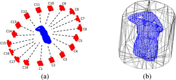
(a) Calibrated camera positions around the subject; (b) Bounding cylinder for calculating a visual hull. The reconstructed visual hull is at the center of the bounding cylinder.
C Visual Hull Construction
The visual hull is constructed based on silhouettes of the target object obtained from the set of multi-view images. The body silhouettes are extracted using the graph cut algorithm [12]. Since the parameters of the multi-view system have been obtained in the calibration process (Section B), we can construct a 3D bounding cylinder which encloses the human body based on the spatial relationship between camera positions and field of views, as shown in Fig. 2(b). Then, the bounding cylinder is uniformly divided into small n×n×n cells. The center of each cell is back projected using the camera parameters onto all the input images. For each cell, if one of the projected positions is outside the body silhouette, it is classified as a background cell. Otherwise, it is categorized to be a foreground cell. Finally, a 3D triangular mesh of the human body is built by applying the marching cube algorithm to the foreground cells. In this process, the cell size controls the resolution of the 3D triangular mesh.
D. Surface Refinement Based on Image Consistency
Due to the imperfection of body segmentation and certain gaps in the body surface data, there are considerable shape deviations between the triangular mesh and the true body surface. In addition, visual hull cannot reconstruct certain concave regions on the body surface [2], as conceptually illustrated in Fig. 3(a). To improve the accuracy of the body reconstruction, a surface refinement method is utilized based on the consistency of inter-image contents. This method requires a reasonably assumption that if the surface is perfectly matched to the true body surface, the local details of images which are obtained by projecting the 3D textured mesh model from different views are supposed to be the same. The refinement process involves two steps. The first step selects an image set Vx for each vertex x of the triangular mesh S such that, for all image elements in Vx, x is visible from the corresponding camera viewpoints The second step is to refine the position of each vertex based on the consistency of image contents in Vx.
Fig. 3.
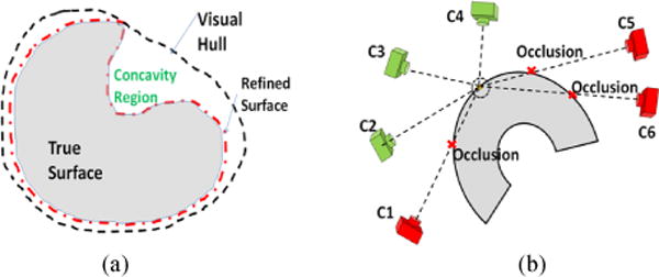
(a) The visual hull may not cover the true surface accurately, especially in a concave region; (b) A particular part of the object can only be seen by some of the cameras (green cameras) due to occlusion.
1) Visibility of Mesh Vertices on Multi-View Images
Generally, a vertex on the mesh surface is visible for a particular image if and only if it is first-encountered along a tracing ray emitted from the corresponding camera, as illustrated in Fig. 3(b). To examine whether a vertex x is visible in an image, we refer to the z-buffer concept utilized in the graphics processing unit (GPU) which records the depth value of each first-encountered mesh vertex in the current viewpoint. We first compute the projection coordinates of vertex x, denoted as (xc, yc, zc), by using available camera parameters. The visibility of the vertex is determined as valid if zc ≤ D(xc, yc), where D is the depth map from the z-buffer. By using this approach, we can efficiently obtain the image set Vx for each vertex x of the triangular mesh S.
2) Mesh Evolution Based on Partial Differential Equation (PDE)
The PDE based mesh evolution method adopts a dual-projection process to refine the 3D body mesh [13]. For each vertex x on the mesh, the first projection is performed to map a patch of image Ij ∈ Vx (neighborhood of image coordinates of x) onto the mesh S, so that the mesh can be textured with the appearance of human body from the viewpoint of Ij. Then, the second projection is carried out to transform the 3D texture patch to the image coordinates of Ii ∈ Vx thus obtaining a simulated image patch. By calculating the similarity of the two patches in image pairs Ii and Ij, we can evaluate the deviation of vertex x on the mesh from its true position of the human body surface. The adopted inter-image consistency metric Mij, between patches in images Ii, and Ij is the normalized cross correlation. By considering each pair of images in Vx, the local consistency function Ω(x) for vertex x in the meshS can be formulated as:
| (1) |
where and are two image patches; and are projection operators from onto S and from S to , respectively. The energy function, E(S), of the body mesh S can then be defined by integrating every vertex on the mesh:
| (2) |
Next, a PDE evolution equation of mesh S can be derived from the energy function (2) as:
| (3) |
| (4) |
where Hx is the mean curvature of the surface in x which is included in (3) as a regulation term to enforce surface smoothness, Ψx is the derivative of Ω(x), t is a time constant which controls the velocity of evolution, and is the norm of surface S in x which determines the direction of evolution. Although good results are reported in a number of benchmark datasets [2], Eqs. (3) and (4) are based on the assumption of rigid object without deformation. Clearly, this assumption is not true for the reconstruction of the human body since, during the imaging process, it is difficult to avoid certain movements, such as those due to breathing and body sways. We alleviate this problem by redefining a different PDE evolution equation:
| (5) |
with
| (6) |
and
| (7) |
where xv ∈ N(x) is a neighborhood of vertex x on the mesh S, μmin minimizes the weighted sum of the differences over derivatives of vertexes xv ∈ N(x) in the L1 norm sense, is the weight for each vertex in N(x), is the mean curvature measured on xv, η and k are two positive constants, and is Euclidean distance. Eq. (6) can be easily and exactly solved by weighted median filter. The advantages of Eqs. (5) through (7) are two folds: first, they consider the entire vertexes in the neighborhood of vertex x, which can enforce a smoother result. Second, because the L1 norm is robust to noise and outliers, it can alleviate the artifacts resulting from the body sways. In practice, the neighborhood N(x) of vertex x can be set as the first or second order ring of the triangular facets around vertex x in triangular mesh.
E. Anthropometric Measurement of Human Body
After a 3D body surface is reconstructed, the measurement on the surface can be conveniently performed. The circumferences (e.g., the hip and waist circumferences) can be measured as intersection curves of the reconstructed 3D human body S and appropriate transverse planes. After manually selecting several points from body surface as an initial point set Φ, a plane ΠΦ is fitted through these points using the least-square-fitting technique. Then, the intersection curve between this plane and the reconstructed body surface is calculated. Any 3D point x near this plane is added to Φ if the following criterion is satisfied
| (8) |
where dist(x, ΠΦ) is the projection distance between 3D vertex x and plane ΠΦ, and T is a threshold to control the number of points that can be added to Φ. This threshold can be determined based on the average length over all the edges of triangular mesh. Plane ΠΦ is updated as long as there are new points in set Φ. This procedure is iterated several times until the plane does not change significantly. Finally, all points in Φ are fitted into a smooth curve using cubic spine interpolation. The length of this intersection curve provides the circumference measurement.
IV. EXPERIMENTAL RESULTS
Two experiments were performed to reconstruct the bodies of an infant mannequin and a human subject. Both the mannequin and the human subject were situated on top of a rotating disk. A digital camera (NIKON D600) was fixed on a tripod. A high resolution image (resolution 6016 × 4016) was acquired at every 20° rotation of the disk.
A. Measurement on Mannequin
The first image dataset was captured from an infant mannequin with tight clothes on the body. The mannequin has a painted surface so that it contains large areas without any textures. Therefore, this was a challenge dataset for 3D reconstruction. The PDE surface evolution step t was set as 0.01, and a Gaussian multi-resolution pyramid was used to overcome certain local minima in PDE evolution. The result of the reconstructed mannequin is shown in Fig 4. Comparing with the visual hull result in Fig. 4(b), it is clear that the refinement result in Fig. 4 (c–d) can recover the small details of the body, such as nose, ear, eyes, etc. Further, the borders between body and clothes are more observable.
Fig. 4.
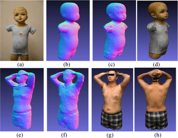
3D reconstruction of mannequin and human: (a) one of the original images of mannequin; (b) 3D surface of mannequin from visual hull; (c) final 3D surface of mannequin after refinement; (d) textured result of mannequin; (e) 3D surface of human body from visual hull; (f) final 3D surface of human body after refinement; (g) – (h) textured result of human body in different views.
A number of anthropometric values, including the hip circumference (HC), waist circumference (WC), waist-to-hip ratio (WHR), neck circumference (NC), and chest circumference (CC) were measured on the 3D model of mannequin. The results are compared in Table I with the results of manual measurements as the ground truth. It can be observed that the errors of the computational measurements were very small.
Table I.
Result of anthropometric measurements on mannequin
| Method | WC(cm) | HC(cm) | WHR | NC(cm) | CC(cm) |
|---|---|---|---|---|---|
|
| |||||
| 3D Model | 3.17% | −0.95% | 4.14% | 1.17% | 4.57% |
| Relative Error | ±2.95% | ±1.51% | ±1.14 | ±4.75% | ±1.47% |
|
| |||||
| Manual | 44.45 | 46.99 | 0.9459 | 22.86 | 48.26 |
B. Measurement on Human Body
The human body dataset was captured from a male volunteer of 29 years of age. Two of the original images have been shown in Fig. 1 (b–c). Because the subject moved slightly due to involuntary body sways in the image acquisition process, Eqs. (5)–(7) were used in the refinement process. The evolution step size t was set as 0.001. As shown in Fig. 5, the appearances of refined surface in Fig. 5 (f–h) were superior to that of the visual hull (Fig. 5 (e)) Although the body was reconstructed accurately, there were clear artifacts in the hand region. The reason was that the hands moved in larger degrees when images were acquired, which made the hands more difficult to be reconstructed. Nevertheless, hands are not the part of the anthropometric measurements. Again, the ground truth for the circumference measurements was provided by manual measurements with a high-quality tape. In addition to the metrics listed in section A, the arm circumference (AC) was also measured for the human subject. Our experimental results are shown in Table II. Although there were movements due to breathing and body sways, the measurements of WC and HC were very close to the ground truth values. The errors of NC, CC and AC were larger than the previous case (still less than 5%), caused by larger body movements in the corresponding body locations These results indicate that our algorithm is highly effective in suppressing errors caused by small movements of the body. However, the effectiveness reduces as the movements become excessive.
Table II.
Result of anthropometric measurements on human body
| Method | WC(cm) | HC(cm) | WHR | NC(cm) | CC(cm) | AC(cm) |
|---|---|---|---|---|---|---|
|
| ||||||
| 3D Model | −1.91% | 1.42% | −3.26% | 4.56% | −3.24% | −4.31% |
| Relative Error | ±2.99% | ±3.17% | ±2.76% | ±3.04% | ±1.20% | ±2.16% |
|
| ||||||
| Manual | 110.5 | 113.5 | 0.9736 | 38.7 | 114.6 | 35.3 |
V. CONCLUSION
We have proposed a prototype system to measure anthropometric parameters in households and clinics. The person being measured only needs to stand on a rotating disk for a short time as a single camera at a fixed location takes pictures repeatedly. The acquired multi-view images are utilized to reconstruct the surface of the human body and measure a number of anthropometric parameters. In our computational algorithms, the imaging system is first calibrated using the structure from motion technique. Then, a coarse 3D triangular mesh model of the human body is built using the silhouettes of the foreground in multi-view images. The generation of this coarse initial mesh not only eases the evaluation of local properties of the 3D surface, such as the norm and the curvature, but also provides an approximate model as an initial base for subsequent iterative refinements using a PDE based mesh evolution. Our experimental results using both a mannequin and a human subject have shown that the proposed system is highly accurate in the measurements of various anthropometric parameters.
Footnotes
This work was supported by National Institutes of Health Grants No. R01CA165255 and U01HL91736 of the United States, and the Research Program No. 61173086 of National Natural Science Foundation of China.
Contributor Information
Zhaoxin Li, Department of Computer Science and Technology, Harbin Institute of Technology, Harbin, China.
Wenyan Jia, The Department of Neurosurgery, University of Pittsburgh, 15213.
Zhi-Hong Mao, Department of Electrical and Computer Engineering, University of Pittsburgh.
Jie Li, The Department of Neurosurgery, University of Pittsburgh, 15213.
Hsin-Chen Chen, The Department of Neurosurgery, University of Pittsburgh, 15213.
Wangmeng Zuo, Department of Computer Science and Technology, Harbin Institute of Technology, Harbin, China.
Kuanquan Wang, Department of Computer Science and Technology, Harbin Institute of Technology, Harbin, China.
Mingui Sun, Email: drsun@pitt.edu, Department of Electrical and Computer Engineering, University of Pittsburgh; The Department of Neurosurgery, University of Pittsburgh, 15213.
References
- 1.World Health Organization. Waist circumference and waist–hip ratio. Report of a WHO expert consultation. 2008;1:8–11. [Google Scholar]
- 2.Seitz SM, Curless B, Diebel J, Scharstein D, Szeliski R. A comparison and evaluation of multi-view stereo reconstruction Algorithms. Proc IEEE Conf CVPR. 2006;1:519–526. [Google Scholar]
- 3.Cheng J, Zheng S, Wu X. Structured light-based shape measurement system of human body. Advances in Artificial Intelligence LNCS. 2011;7106:531–539. [Google Scholar]
- 4.Yang T, Zhang Y, Li M, Shao D, Zhang X. A multi-camera network system for markerless 3D human body voxel reconstruction. Proc of Int’l Conf on Image and Graphics. 2010;1:706–711. [Google Scholar]
- 5.Yamauchi K, Kameshima H, Saito H, Sato Y. 3D reconstruction of a human body from multiple viewpoints. Second Pacific Rim Symposium. 2007;4872:439–448. [Google Scholar]
- 6.Weinberg SM, Naidoo S, Govier DP, Martin RA. Anthropometric precision and accuracy of digital three-dimensional photogrammetry: comparing the Genex and 3dMD imaging systems with one another and with direct anthropometry. J Craniofac Surg. 2006;17(3):477–83. doi: 10.1097/00001665-200605000-00015. [DOI] [PubMed] [Google Scholar]
- 7.Wong JY, Oh AK, Ohta E, Hunt AT, Rogers GF. Validity and reliability of craniofacial anthropometric measurement of 3D digital photogrammetric images. Cleft Palate Craniofac. 2008;45(3):232–239. doi: 10.1597/06-175. [DOI] [PubMed] [Google Scholar]
- 8.Bradley D, Heidrich W, Popa T, Sheffer A. High resolution passive facial performance capture. ACM Transactions on Graphics. 2010;29(4):1–10. [Google Scholar]
- 9.Zhang Z. A flexible new technique for camera calibration. IEEE Transactions on PAMI. 2000;22(11):1330–1334. [Google Scholar]
- 10.Chum O, Matas J, Kittler J. Locally optimized RANSAC. DAGM Symposium for Pattern Recognition. 2003;1:236–243. [Google Scholar]
- 11.Triggs B, McLauchlan PF, Hartley RI. Bundle adjustment: a modern synthesis. Proc of Int’l Workshop on Vision Algorithms: Theory and Practice. 1999;1:298–372. [Google Scholar]
- 12.Rother C, Kolmogorov V, Blake A. GrabCut: interactive foreground extraction using iterated Graph Cuts. ACM Transactions on Graphics. 2004;23(3):309–314. [Google Scholar]
- 13.Pons JP, Keriven R, Faugeras O. Multi-view stereo reconstruction and scene flow estimation with a global image based matching score. Int’l J Computer Vision. 2007;72(2):179–193. [Google Scholar]