Abstract
In this paper, we demonstrate the possibility to trap and sort labeled cells under flow conditions using a microfluidic device with an integrated flat micro-patterned hard magnetic film. The proposed technique is illustrated using a cell suspension containing a mixture of Jurkat cells and HEK (Human Embryonic Kidney) 293 cells. Prior to sorting experiments, the Jurkat cells were specifically labeled with immunomagnetic nanoparticles, while the HEK 293 cells were unlabeled. Droplet-based experiments demonstrated that the Jurkat cells were attracted to regions of maximum stray field flux density while the HEK 293 cells settled in random positions. When the mixture was passed through a polydimethylsiloxane (PDMS) microfluidic channel containing integrated micromagnets, the labeled Jurkat cells were selectively trapped under fluid flow, while the HEK cells were eluted towards the device outlet. Increasing the flow rate produced a second eluate much enriched in Jurkat cells, as revealed by flow cytometry. The separation efficiency of this biocompatible, compact micro-fluidic separation chamber was compared with that obtained using two commercial magnetic cell separation kits.
INTRODUCTION
Isolation, sorting, and enrichment of target cells from heterogeneous suspensions is of growing interest and has broad importance in several applications such as cell therapeutics,1 stem cell research,2 and cancer diagnostics.3 Conventional technologies available for the isolation and separation of cells often rely on the use of bioaffine ligands, offering high specificity, and great diversity. Antibodies tagged with fluorophores or magnetic beads can be attached to target cells based on specific antibody/antigen recognition, which allows immunolabeling-based cell separation using flow cytometry or magnetic-activated cell sorting. In some cases, it is also possible to magnetically label cells without using particles. For instance, cells containing a high amount of iron, like cardiomyocytes, can be rendered transiently paramagnetic by treatment with oxidant molecules.4
Several companies such as Miltenyi Biotec, Dynal Biotech, Polysciences, Ademtech, or Chemicell have developed superparamagnetic particles of controlled size, coated with specific antibodies and dedicated to biomagnetic separation. Some of these particles are even composed of biodegradable materials, lowering their impact on cells.
Immunomagnetic enrichment of cells can be performed using different commercial equipment, such as the MACS® system (Miltenyi Biotec), CellSearch System (Veridex, Warren, NJ), and MPC separator series (Dynal AS). Recently reported approaches based on the combination of magnetism and microfluidics have also emerged as viable high throughput and low cost alternatives to powerful but bulky and expensive separation equipment such as the FACS (Fluorescence Activated Cell Sorter) or CellSearch® systems.5 A commonly used strategy consists in placing a bulk permanent magnet in the vicinity of a microfluidic channel to deflect magnetically labeled targets out of the main stream.6, 7, 8 This approach was successfully used for instance by Robert9 to perform continuous sorting of cells based on their endocytotic capacity. However, bulk magnets generate low values of magnetic field gradient and thus low magnetic forces. Such a device may therefore fail to discriminate between unlabelled cells and cells carrying weak magnetic moments (e.g., cells labelled with ultra small particles of iron oxide (USPIO)). Since the magnetic force exerted on an object is determined by both its magnetic moment and the magnetic field gradient it experiences,10 one solution to improve sensitivity lies in the miniaturization of the magnetic flux source, which leads to an increase of the magnetic field gradient.
Micro-electromagnets are suitable for the production of variable field gradients11 and different designs have been employed, such as single wires12 and micro-coil arrays.13 This approach enables dynamic reconfiguration of the magnetic field patterns, but has the drawback of generating Joule heating, which limits considerably the maximum value of generated magnetic field, and thus field gradient, and may have adverse effects on cell viability.
Another approach used to generate strong magnetic field gradients inside a microfluidic device consists in embedding soft ferromagnetic elements at the bottom of a microchannel to concentrate flux from an external magnetic field source (e.g., a bulk permanent magnet or electromagnet). Compared to micro-electromagnets, such micro-patterned flux concentrators allow the production of substantially stronger magnetic fields while avoiding heat generation. Inglis14 and coworkers followed by Adams et al.15 and more recently by Kim et al.16 have performed continuous flow immunomagnetic cell separation in microfluidic devices using integrated soft magnetic stripe structures inclined at an angle to the flow direction, and magnetized by an external bulk permanent magnet.
Compared to soft magnetic structures, hard magnetic structures have the advantage that once they've been magnetized, no external field source is needed to produce a stray magnetic field around the structure. They can be used to produce compact, autonomous (no power supply) magnetic traps, and are thus of great interest for lab-on-chip or point of care devices. Issadore et al.17 have reported the use of a microfluidic channel positioned above a layer of PDMS containing hard magnetic NdFeB powders, to sort tumor cells from leukocytes using negative immunomagnetic selection. The strength of the magnetic field gradient was adjusted from the beginning to the end of the channel by varying the particle size of the powder. However, the maximum stray field value produced by a given powder particle is limited by the isotropic nature of the powder used (i.e., each particle is composed of many grains which are isotropically oriented, resulting in a reduced value of remanent magnetization).
High rate triode sputtering can be used to prepare highly textured thick films of NdFeB18 (the constituent grains are aligned, which maximizes the material's remanent magnetization). Micro-patterning of such films, using topographic (lithography)19 or thermo-magnetic (temperature control of magnetization reversal)20 approaches, produces micron-sized permanent magnets characterized by stray magnetic field gradients as high as 106 T/m.21 The flat surface of thermo-magnetically patterned films facilitates their integration into microfluidic devices, and they have been used to trap magnetic particles (SiO2 and polystyrene particles containing magnetic nanoparticles) within such a device.22 In this paper, we report the use of a microfluidic device containing integrated thermo-magnetically patterned NdFeB films for cell separation using immunomagnetic beads. We demonstrate the device efficiency by performing Jurkat cell enrichment from an artificial mixture of Jurkat and HEK 293 (Human Embryonic Kidney; ATCC, CRL-1573) cells. Our purpose is to show that even poorly labeled cells can be efficiently enriched using a microfluidic cell separator with high magnetic field gradient micro-flux sources.
MATERIALS AND METHODS
Cell preparation
Cell culture
Cell culture media and supplements were purchased from PAA. Jurkat cells (human leukemia T cells; ATCC, TIB-152) with an average diameter of 8 μm were grown at 37 °C with 5% CO2 in Roswell Park Memorial Institute (RPMI) 1640 medium supplemented with 10% fetal bovine serum (FBS), 100 μg/ml streptomycine and 100 U/ml penicillin. HEK 293 cells were cultured at 37 °C under 5% CO2 in Dulbecco's Modified Eagle Medium high glucose (DMEM) supplemented with 10% FBS, 100 μg/ml streptomycin, and 100 U/ml penicillin. The HEK 293 cells have a mean cell diameter of 15 μm in suspension.
Cell fluorescent labeling
CellTrackerTM probes were purchased from Invitrogen (UK). The CellTrackerTM Green CMFDA (5-chloromethylfluorescein diacetate) lyophilized product was dissolved in dimethyl sulfoxide to a final concentration of 10 mM. The stock solution was then diluted to a final working concentration of 25 μM in serum-free medium. Jurkat cells were harvested by centrifugation and resuspended in 1 ml of RPMI medium containing 50 μl of CellTrackerTM dye working solution, before being incubated at 37 °C for 45 min. The probe absorption and fluorescence emission maxima are 492 nm and 517 nm, respectively.
The CellTrackerTM Orange CMTMR (5-(and-6)-(((4-chloromethyl)benzoyl)amino)) was used to label HEK 293 cells, which are adherent cells. Once cells had reached confluence, they were trypsinized and resuspended in 1 ml DMEM medium supplemented with 50 μl of CellTrackerTM dye working solution at 25 μM concentration. Cells were then incubated at 37 °C for 45 min. The orange colored fluorescent dye has absorption and emission maxima at 527 and 558 nm, respectively.
Cell immunomagnetic labeling
Cells were immunomagnetically labelled with 50 nm streptavidin-coated super-paramagnetic nanoparticles (μMACSTM Streptavidin MicroBeads, Miltenyi Biotec). The particle hydrodynamic diameter was measured by Dynamic Light Scattering using a Zetasizer Nano S (Malvern). A unimodal size distribution was obtained, peaking at 69 nm.
107 Stained Jurkat and HEK cells (ratio 1:3) were transferred in 100 μl Phosphate Buffer Saline (PBS) supplemented with 2% FBS and 2 mM EDTA (isolation buffer). Cells were then incubated for 20 min at 4 °C with 20 μl of biotin conjugated monoclonal antibody (Thermo-Scientific) directed against the CD3 antigen expressed on Jurkat cells. Cells were then washed to remove excess antibody and resuspended in 97 μl of isolation buffer. Afterwards, the mixture was incubated with 3 μl of μMACSTM Streptavidin MicroBeads for 15 min at 4 °C with gentle agitation. Streptavidin-coated magnetic nanoparticles were bound to biotinylated antibodies used against CD3 antigens expressed on the Jurkat cell surface. Cells were washed by adding 1 ml of buffer and centrifugated at 300 × g for 10 min. After removal of the supernatant, they were resuspended in 1 ml of isolation buffer.
Micromagnet fabrication
The micro-magnet arrays were developed using the thermo-magnetic patterning technique (TMP), described by Dumas-Bouchiat et al.20 Briefly, the process began with the deposition and annealing of an out-of-plane textured NdFeB film (5 μm thick) by high-rate triode sputtering. The film was then saturated in the out-of-plane direction in a field of 7 T, produced using a superconducting coil. A nanosecond pulsed laser beam was then used to irradiate specific regions of the film through a mask, in an external magnetic field of strength lower than the room temperature coercivity of the film, and pointing in the direction opposite to the film's magnetization. The coercivity of the irradiated zones dropped due to the increase in temperature, resulting in localized magnetization reversal. The flux density at the surface of these micro-patterned structures is maximal at the boundaries between oppositely magnetized domains.21
Microfluidic integration
Integration of the micromagnet array into a microfluidic channel was performed in two steps. First, a PDMS microchannel was fabricated by replica molding using a dry film photoresist.23 Then, a thin PDMS layer was coated onto the magnetic film surface to facilitate microchannel bonding by air plasma and to provide a biocompatible surface for cell attraction. This layer also serves to protect the magnetic film from corrosion.
Microchannel fabrication procedure
A 50 μm thick dry photoresist layer (LAMINAR™ E92200 dry film photopolymer) was laminated by hand onto a glass substrate before exposure to ultraviolet light through a photomask bearing the microchannel geometry (using KLOE UV-KUB exposure and masking system, wavelength 365 nm). The exposed negative photoresist film was then developed in a Na2CO3 solution at a concentration of 0.85% w/w, heated to 35 °C. PDMS preparation consisted in mixing Sylgard 184 silicone base and curing agent (purchased from Neyco) at 10:1 mass ratio. After vacuum degassing, the mixture was poured over the PDMS master and allowed to cure in an oven at 80 °C for 2 h. After peeling off the PDMS replica, two holes were punched at each end of the microchannel.
Microchannel bonding
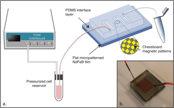
The same PDMS mixture as described above was diluted with Heptane (Sigma-Aldrich) to obtain a 4% w/w PDMS solution. The dilute solution was spin-coated onto the magnet surface at 4500 rpm for 1 min (using a Spin 150, SPS) and baked at 80 °C for a few hours to enable solvent evaporation and PDMS curing. The obtained layer thickness was measured with a Dektak 3030 surface profiler and found to be equal to 300 nm. The PDMS microchannel and the PDMS-coated substrate were then sealed together after exposing both surfaces to air plasma treatment (Expanded Plasma Cleaner, Harrick Plasma). A schematic of the microfluidic device is presented in Fig. 1.
Figure 1.
(a) Schematic diagram of the experimental setup. (b) Photograph of the compact microfluidic chip with integrated micromagnets.
Cell separation
After incubation with μMACSTM Streptavidin MicroBeads, cell separation was performed using three different cell separators (the microfluidic device, the miniMACSTM separator from Miltenyi Biotec and the DynaMagTM from Invitrogen). In each case, the sample processed contained Jurkat and HEK cells present at concentrations of 2.5 × 10⁶ cells/ml and 7.5 × 10⁶ cells/ml, respectively.
Magnetic separation with the Mini-MACS system
As regards magnetic separation using the MiniMACSTM, the cell separation column (MS column) was first placed in the MiniMACSTM separator and rinsed with 500 μl of isolation buffer. Cells resuspended in 500 μl of isolation buffer where then loaded onto the MS column. Unlabeled cells flowed through while the magnetically labeled cells were retained in the column. The retained material was washed three times with 500 μl buffer to remove unlabeled material.
After removal of the MS column from the magnetic field, the magnetically retained cells were eluted as the positively selected cell fraction (which was analyzed by flow cytometry) by pipetting 1 ml of isolation buffer onto the column and pushing the plunger into the column.
Magnetic separation with the Dynal system
The separation protocol used with the Dynal system consisted in placing the tube containing the cell mixture in the DynaMagTM Magnet for 2 mn. The magnetically labeled cells were drawn to the side of the tube facing the magnet, and the supernatant was discarded (the protocol followed was based on the instructions given by the manufacturer for positive isolation of cells using Dynabeads® CD3). Finally, the tube was removed from the magnet and cells were resuspended in 1 ml of isolation buffer before analysis by flow cytometry.
Magnetic separation with the microfluidic device
The experimental setup used for microfluidic cell separation is described in Fig. 1. 1 ml of a cell suspension was introduced into the microfluidic magnetic cell separator. The flow inside the microchannel was controlled using a pressure-driven flow controller (Fluigent MFCS) at a rate of 1.2 ml/h, enabling entrapment of labeled cells. After the entire sample had been passed through the microchannel, 500 μl of isolation buffer was introduced into the channel at the same flow rate, as a rinsing step. Following this, Jurkat cells were gently released from their magnetic trap by increasing the flow rate to 2 ml/h. This second eluate was collected at the channel outlet for further analysis by flow cytometry. The enrichment step was performed in approximately 1 h.
Flow cytometry
Flow cytometry was performed using a 4-laser cytometer (BD LSRFortessa SORP, BD Biosciences) and analyzed using FACSDiva Version 6.1.3 software (BD Biosciences). Cells were run through the instruments unfixed. Data were collected from at least 10 000 events and gated to remove debris and clusters.
RESULTS AND DISCUSSION
Single droplet trapping experiments
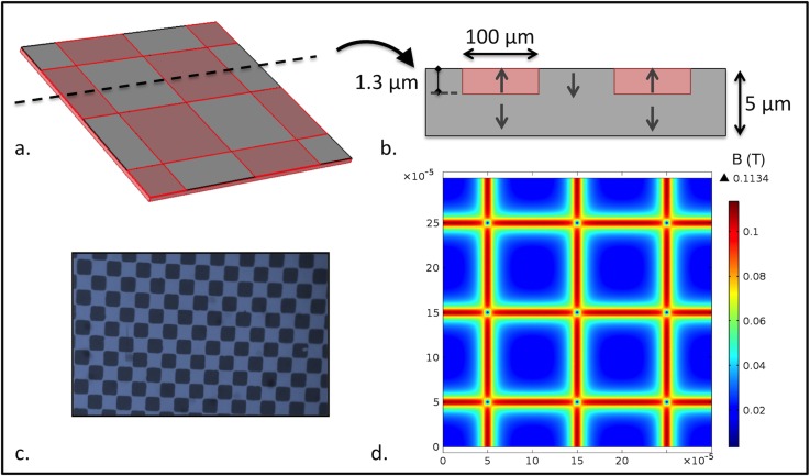
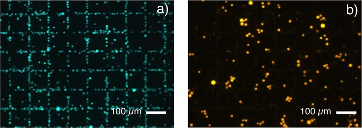
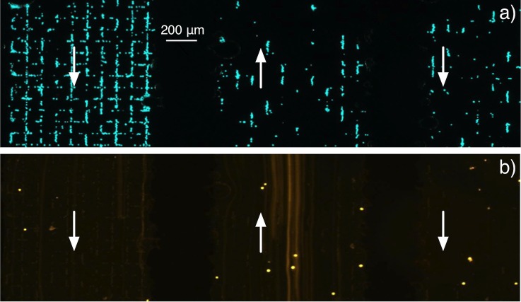
The capability of micromagnets to trap cells labeled with 50 nm magnetic particles was firstly tested in droplet mode with a mixture of Jurkat and HEK 293 cells. Trapping tests were carried out with chessboard magnetic patterns of dimensions 100 × 100 μm2 with no PDMS coating. The sample consisted of the Jurkat cells labeled with 50 nm magnetic particles and unlabeled HEK 293 cells. The norm of the simulated magnetic flux density in a plane situated 4 μm above the micromagnet array is represented in Fig. 2d. This height corresponds to the mean distance between the center of a trapped cell and the TMP magnet surface. Fig. 3a shows Jurkat cells attracted towards regions of maximum flux density owing to the strong stray magnetic field gradients generated at the edges of the miniaturized magnets. Indeed, trapping of target cells resulted in the formation of fluorescent patterns at locations of highest magnetic flux density, thus delineating the boundaries between oppositely magnetized micromagnets, i.e., the use of patterned magnetic structures facilitates the easy recognition of specific capture. On the contrary, unlabeled HEK 293 cells settled randomly upon the surface of micro-magnets (Fig. 3b). These results demonstrated specific trapping of Jurkat cells labeled with small magnetic nanoparticles (50 nm) and the possibility of using flat micropatterned magnetic films to perform immunomagnetic cell separation. The device can be adapted to cell sorting by sealing a PDMS microchannel on top of the micromagnets. The proposed technique consists in coating the TMP magnet surface with a very thin PDMS layer, acting as an interface layer for plasma bonding of the PDMS lid. This technique leads to irreversible bonding between the PDMS layer and the PDMS channel, but, if required, the resulting closed chamber formed on top of the micromagnet array can be pulled off the substrate, leaving the TMP film reusable for further experiments.19 The thin PDMS membrane also contributes to reduce non-specific adsorption of cells observable on uncoated magnetic films.
Figure 2.
(a) Partial representation of the micromagnet array. (b) Cross-sectional view showing the direction of magnetization in the chessboard squares. The typical depth of magnetization reversal is estimated to be 1.3 μm.20 (c) Photograph of the square patterns (100×100 μm2) revealed by magneto-optical imaging. (d) Norm of the magnetic flux density B in the plane situated 4 μm above the magnetic film surface.
Figure 3.
Droplet experiments: (a) Attraction of magnetically labeled Jurkat cells towards magnetic field maxima at the surface of a micromagnet array (Chessboard magnetic pattern, 100 × 100 μm2). (b) Unlabeled HEK 293 cells randomly dispersed above the micromagnet array.
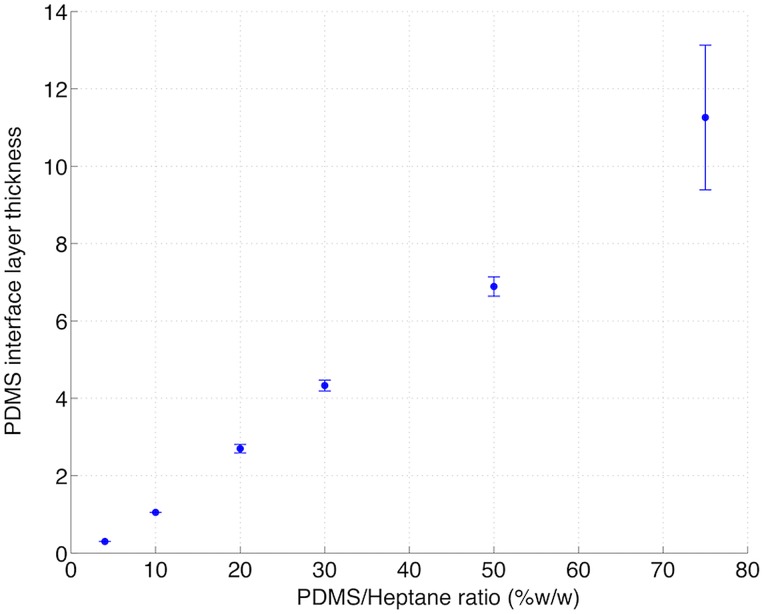
To evaluate the impact of the intermediate PDMS layer on cell attraction, we performed trapping experiments on a TMP magnetic film partially coated by this thin layer. Prior to spin coating of hexane-diluted PDMS, a piece of adhesive tape was sealed onto the TMP surface. After tape removal, two distinct regions were obtained on the surface of the TMP magnet, one being covered with PDMS, the other remaining uncoated. Trapping results are shown on Fig. 4. When PDMS/heptane was poured in a 20% w/w ratio, magnetically labeled Jurkat cells randomly settled on the coated TMP surface, while they clearly organized themselves along the square patterns on the uncoated side (Fig. 4a). This PDMS/heptane ratio yielded a 3 μm layer thickness, as indicated in Fig. 5. Fig. 4b shows that when PDMS/heptane was poured in a 4% w/w ratio, corresponding to a layer thickness of 300 nm, the target cells were forming square patterns on the whole surface. This layer thickness has therefore been retained for the microfluidic device fabrication.
Figure 4.
Repartition of magnetically labeled Jurkat cells on top of a TMP magnet partially coated with (a) a 3 μm thick PDMS layer (b) a 300 nm thick PDMS layer. Above the limit indicated by the dashed line, cells were in direct contact with the TMP surface.
Figure 5.
Impact of the PDMS/Heptane ratio on the PDMS layer thickness (μm), plotted for a spin coating rate of 4500 rpm and a 1 min duration.
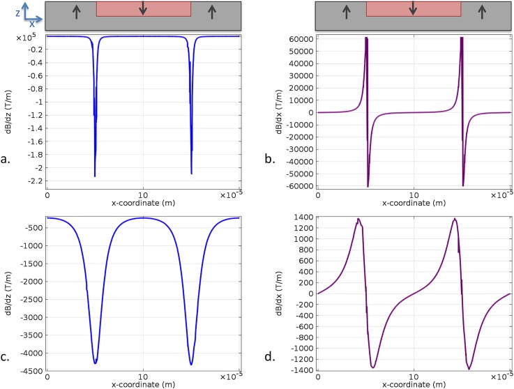
The rapid diminution of cell attraction with the distance to the TMP film surface can be understood by referring to Fig. 6, depicting the evolution of magnetic field gradient with this distance. Indeed, the magnetic force imparted on cells is proportional to ∇B,24 which must reach very high values to enable attraction of cells carrying weak magnetic loads.
Figure 6.
Simulation of the magnetic field gradients generated at a distance of 1 μm ((a) and (b)) and 10 μm ((c) and (d)) from the TMP magnet surface.
Jurkat cell enrichment
In order to perform selective trapping of Jurkat cells under flow conditions, the chessboard micromagnet array was integrated into a microfluidic channel (see enlarged area in Fig. 1). A mixture containing 25% of magnetically labeled Jurkat and 75% of unlabeled HEK 293 cells was introduced in the microfluidic magnetic cell separator. Fig. 7a shows entrapment of green-stained Jurkat cells labeled with 50 nm magnetic nanoparticles at the regions of maximum magnetic flux density under a 1.2 ml/h flow rate. Almost no orange-stained cells were observed at the micromagnet surface, as unlabeled HEK 293 cells were eluted towards the microchannel outlet (Fig. 7b). The serpentine structure is designed to increase the distance traveled by cells above the TMP surface, so as to maximize the recovery rate of target cells. As many cells are attracted in the first serpentine sub-channel, there is a visible diminution of cell number in the following ones.
Figure 7.
(a) Selective trapping of Jurkat cells under continuous flow (microchannel dimensions—width: 1 mm, height: 50 μm). The arrows indicate flow direction in three adjacent serpentine sub-channels. (b) Observation of HEK 293 cells passing above the same area through the serpentine using long exposure.
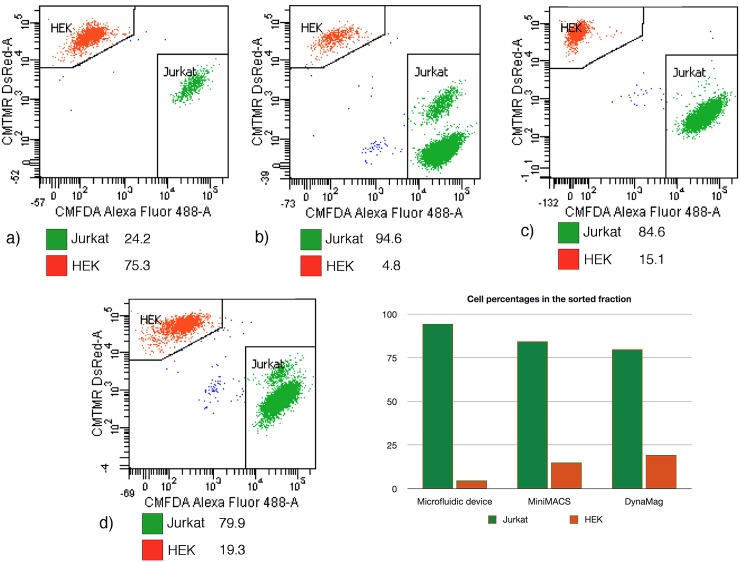
After the entire sample (1 ml) had been passed through the microchannel, 500 μl of isolation buffer were introduced into the channel at the same flow rate, as a rinsing step. Following this, Jurkat cells were gently released from their magnetic trap by increasing the flow rate to 2 ml/h. Analysis of this second eluate by flow cytometry (Fig. 8b) revealed that it contained around 94.6 ± 1.0% of Jurkat cells (the precision being calculated based on Poisson statistical distribution, from the total number of events in the gated population25). To provide a comparison, the results obtained with two fractions of the same initial mixture, respectively, passed through a miniMACS separation column (Miltenyi Biotec) and through a Dynal® magnet (Invitrogen) were also analyzed. Using these magnetic columns, Jurkat cells were enriched to 84.6 ± 1.0% and 79.9 ± 0.9% purity, respectively (Figs. 8c, 8d). It should be noted that the same protocol was intentionally used with the three separators, in order to compare their separation efficiency, which means that the protocols provided by the manufacturers where not strictly followed. As MACS MicroBeads used in our experiments are very small superparamagnetic particles (50 nm), a high-gradient magnetic field is required to retain efficiently the labeled cells. The permanent micromagnets integrated in the microfluidic device are capable of generating a high magnetic field gradient approaching 106 T/m at the magnetic film surface.21 The miniMACS is a commercial system dedicated to high-gradient magnetic cell separation. Indeed, MS Columns contain an optimized matrix composed of ferromagnetic spheres, which concentrate the field lines when placed in the magnetic field of the MiniMACS Separator, thus inducing a high gradient within the column. The purity value obtained with the MACS is lower than that obtained using the microfluidic separation device, probably because despite the large magnetic field gradient produced, the device is still optimized for the sorting of labeled cells presenting higher magnetic moments than in our experiment. Indeed, the nanoparticle quantity used in our study is more than three times lower than the value recommended by the manufacturer (10 μl for 107 cells suspended in 90 μl of separation buffer, versus 3 μl in our experiments). The purity obtained with the Dynal system (around 80%) is the lowest among the three trials. This result must however be interpreted cautiously, as washing steps normally included after the initial removal of the supernatant had to be skipped to enable cell recovery. Indeed this separation device is normally optimized for the use of particles featuring a much larger size (for instance, Dynabeads® CD3, which enable isolation of human CD3 + cells, are 4.5 μm in diameter). Additional washing steps had the effect of reducing dramatically the quantity of cells retained on the magnet, which can be explained by the weak magnetic load carried by labeled cells combined with the weak field gradient produced by the Dynal magnet.
Figure 8.
(a) Composition of the sample introduced in the different cell separators (percentage values). (b) Composition of the second eluate collected at the microfluidic device outlet. (c) Cells released from the miniMACS column. (d) Cells released from the DynaMagTM magnet.
These results demonstrate that a compact microfluidic-based cell separator with integrated permanent micromagnets can be used to perform efficient cell sorting using a minimum amount of magnetic nanoparticles. As for the MACS system, it can be used for positive cell selection. Indeed, the very small MACS MicroBeads (50 nm) can remain attached to the cell after isolation, as they have so far not been found to have any detrimental effects on cell growth or functions. The high magnetic field gradient in our magnetic cell separator, which enables a lowering of the magnetic load attached to cells, can contribute to reduce the potential impact of labeling on cells.
CONCLUSIONS
This paper reports immunomagnetic positive selection of magnetically labeled Jurkat cells from HEK cells in a microfluidic device with integrated micro-magnets. Compared to micro-coils or soft micro-magnets, hard micro-magnets offer the advantage of needing neither a power supply nor an external magnetic field, making them very attractive for lab-on-chip and point of care devices, where ease of use and device size is relevant. Compared to devices using isotropic particles dispersed in a polymer matrix, the micro-patterned highly textured films used here exploit more fully the intrinsic magnetization of the hard magnetic material, and allow for easy identification of specific capture thanks to pattern formation. The high field gradients produced by the integrated micro-patterned hard magnetic films allowed enrichment of cells presenting weak magnetic moments with high purity. The levels of purity obtained were greater than those achieved with the MACS and Dynal separators, for comparable amounts of magnetic material attached to cells. A thin PDMS membrane was used as an interface for microchannel bonding to allow microfluidic integration of the flat micropatterned NdFeB film. The fabricated PDMS separation chamber can be pulled off the magnetic film surface after the experiment and replaced by another one, which allows the magnet array to be reused. The two-step batch separation procedure (trapping-elution) allowed by the device presented here is similar to that used in conventional cell separators, which simplifies comparison. As a perspective of this work, we intend to adapt the magnetic micro patterns and channel design to allow cell sorting under continuous flow. High field gradient micro-patterned hard magnetic films (both thermomagnetically and topographically patterned films) are of great potential interest for a wide range of uses in biology (specific capture for both diagnostic and therapeutic applications, cell positioning, force actuators in mechano-transduction studies….) and beyond.
ACKNOWLEDGMENTS
The authors thank the Région Rhône-Alpes (Cluster Micro Nano) for the financial support provided, including the Ph.D. grant of O.O. They also gratefully acknowledge partial funding from the French National Research Agency (ANR- 08-CESA- 013-01). Special thanks also to Laure Franqueville for her valuable advice regarding cell culture work and to Isabelle Durand at CRCL (Centre de Recherche en Cancérologie de Lyon) for her technical assistance and expertise in flow cytometry. The authors would like to thank Sophie Rivoirard, Isabelle Gelard, and Pierre Frédéric Sibeud, for their assistance in the use of facilities at CRETA (CNRS, Grenoble).
References
- Mohr M., Dalmis F., Hilgenfeld E., Oelmann E., Zühlsdorf M., Kratz-Albers K., Nolte A., Schmitmann C., Onaldi-Mohr D., Cassens U., Serve H., Sibrowski W., Kienast J., and Berdel W. E., Clin. Cancer Res. 7, 51 (2001). [PubMed] [Google Scholar]
- De Coppi P., Bartsch G., Siddiqui M. M., Xu T., Santos C. C., Perin L., Mostoslavsky G., Serre A. C., Snyder E. Y., Yoo J. J., Furth M. E., Soker S., and Atala A., Nat. Biotechnol. 25, 100 (2007). 10.1038/nbt1274 [DOI] [PubMed] [Google Scholar]
- Gascoyne P. R. C., Noshari J., Anderson T. J., and Becker F. F., Electrophoresis 30, 1388 (2009). 10.1002/elps.200800373 [DOI] [PMC free article] [PubMed] [Google Scholar]
- Sofla A., Cirkovic B., Hsieh A., Miklas J. W., Filipovic N., and Radisic M., Biomicrofluidics 7, 014110 (2013). 10.1063/1.4791649 [DOI] [PMC free article] [PubMed] [Google Scholar]
- Pamme N., Lab Chip 6, 24 (2006). 10.1039/b513005k [DOI] [PubMed] [Google Scholar]
- Lin Y.-H., Chen Y.-J., Lai C.-S., Chen Y.-T., Chen C.-L., Yu J.-S., and Chang Y.-S., Biomicrofluidics 7, 024103 (2013). 10.1063/1.4794974 [DOI] [PMC free article] [PubMed] [Google Scholar]
- Svobodova Z., Mohamadi M. R., Jankovicova B., Esselmann H., Verpillot R., Otto M., Taverna M., Wiltfang J., Viovy J.-L., and Bilkova Z., Biomicrofluidics 6, 24126 (2012). 10.1063/1.4722588 [DOI] [PMC free article] [PubMed] [Google Scholar]
- Pamme N. and Wilhelm C., Lab Chip 6, 974 (2006). 10.1039/b604542a [DOI] [PubMed] [Google Scholar]
- Robert D., Pamme N., Conjeaud H., Gazeau F., Iles A., and Wilhelm C., Lab Chip 11, 1902 (2011). 10.1039/c0lc00656d [DOI] [PubMed] [Google Scholar]
- Furlani E. P., in Microfluidic Devices in Nanotechnology (John Wiley & Sons, Inc., 2010), pp. 215–262. [Google Scholar]
- Smistrup K., Tang P. T., Hansen O., and Hansen M. F., J. Magn. Magn. Mater. 300, 418 (2006). 10.1016/j.jmmm.2005.05.031 [DOI] [Google Scholar]
- Plouffe B. D., Lewis L. H., and Murthy S. K., Biomicrofluidics 5, 13413 (2011). 10.1063/1.3553239 [DOI] [PMC free article] [PubMed] [Google Scholar]
- Ramadan Q., Poenar D. P., and Yu C., Microfluid. Nanofluid. 6, 53 (2009). 10.1007/s10404-008-0296-2 [DOI] [Google Scholar]
- Inglis D. W., Riehn R., Austin R. H., and Sturm J. C., Appl. Phys. Lett. 85, 5093 (2004). 10.1063/1.1823015 [DOI] [Google Scholar]
- Adams J. D., Kim U., and Soh H. T., Proc. Natl. Acad. Sci. U.S.A. 105, 18165 (2008). 10.1073/pnas.0809795105 [DOI] [PMC free article] [PubMed] [Google Scholar]
- Kim S., Han S.-I., Park M.-J., Jeon C.-W., Joo Y.-D., Choi I.-H., and Han K.-H., Anal. Chem. 85, 2779 (2013). 10.1021/ac303284u [DOI] [PubMed] [Google Scholar]
- Issadore D., Shao H., Chung J., Newton A., Pittet M., Weissleder R., and Lee H., Lab Chip 11, 147 (2011). 10.1039/c0lc00149j [DOI] [PMC free article] [PubMed] [Google Scholar]
- Dempsey N. M., Walther A., May F., Givord D., Khlopkov K., and Gutfleisch O., Appl. Phys. Lett. 90, 092509 (2007). 10.1063/1.2710771 [DOI] [Google Scholar]
- Walther A., Marcoux C., Desloges B., Grechishkin R., Givord D., and Dempsey N. M., J. Magn. Magn. Mater. 321, 590 (2009). 10.1016/j.jmmm.2008.09.028 [DOI] [Google Scholar]
- Dumas-Bouchiat F., Zanini L. F., Kustov M., Dempsey N. M., Grechishkin R., Hasselbach K., Orlianges J. C., Champeaux C., Catherinot A., and Givord D., Appl. Phys. Lett. 96, 102511 (2010). 10.1063/1.3341190 [DOI] [Google Scholar]
- Kustov M., Laczkowski P., Hykel D., Hasselbach K., Dumas-Bouchiat F., O'Brien D., Kauffmann P., Grechishkin R., Givord D., Reyne G., Cugat O., and Dempsey N. M., J. Appl. Phys. 108, 063914 (2010). 10.1063/1.3486513 [DOI] [Google Scholar]
- Zanini L. F., Dempsey N. M., Givord D., Reyne G., and Dumas-Bouchiat F., Appl. Phys. Lett. 99, 232504 (2011). 10.1063/1.3664092 [DOI] [Google Scholar]
- Stephan K., Pittet P., Renaud L., Kleimann P., Morin P., Ouaini N., and Ferrigno R., J. Micromech. Microeng. 17, N69 (2007). 10.1088/0960-1317/17/10/N01 [DOI] [Google Scholar]
- Inglis D. W., Riehn R., Sturm J. C., and Austin R. H., J. Appl. Phys. 99, 08K101 (2006). 10.1063/1.2165782 [DOI] [Google Scholar]
- Darzynkiewicz Z., Robinson J. P., and Roederer M., Essential Cytometry Methods (Academic Press, 2009). [Google Scholar]


