Abstract
This paper presents a theoretical development and critical analysis of the burst frequency equations for capillary valves on a microfluidic compact disc (CD) platform. This analysis includes background on passive capillary valves and the governing models/equations that have been developed to date. The implicit assumptions and limitations of these models are discussed. The fluid meniscus dynamics before bursting is broken up into a multi-stage model and a more accurate version of the burst frequency equation for the capillary valves is proposed. The modified equations are used to evaluate the effects of various CD design parameters such as the hydraulic diameter, the height to width aspect ratio, and the opening wedge angle of the channel on the burst pressure.
Keywords: Microfluidics, Centrifugal, Compact disc (CD), Burst frequency equation, Passive valve
1 Introduction
In recent years, there has been an increasing interest in the area of microfluidics for biochemical/biomedical applications. One particular area of microfluidics research is the development of microfluidic compact disc (CD) platforms that operate on the basis of centrifugal pumping. A microfluidic CD allows for the miniaturization of large and expensive equipment, reduction in reagent usage, faster heating and cooling, efficient chromatographic and electrophoretic separations, and low-cost fabrication [23, 32].
On a microfluidic CD, a wide range of processes such as valving, decanting, calibration, mixing, metering, heating, sample/volume splitting, separation, siphoning, flow rate control, droplet generation, etc. are possible [9, 23, 32]. Based on this wide variety and availability of processes, implementation of complex assays such as the enzyme-linked-immunosorbent assay (ELISA) is possible on CDs. Some examples are the detection of rat IgG from a hybridoma cell culture by Lai et al. [17], the detection of Dengue non-structural protein 1 (NS-1) by Yusoff et al. [29], the implementation of a 5-step ELISA through a simple 2-layer design by Ibrahim et al. [15], the detection of a cytokine interferon-gamma by He et al. [14], plasma separation and detection of Hepatitis B virus by Lee et al. [18], and allergen screening by Chen et al. [5]. Recent developments have also introduced various enhancements to the basic CD valve design such as suction-enhanced siphon valve by Gorkin et al. [13], semi-circular valve by Lin et al. [21], ice valve by Amasia et al. [2], thermally actuated elastomer valve by Pitchaimani et al. [27], wax valves by Lee et al. [18] and Abi-Samra et al. [1], and dissolvable film valve by Gorkin et al. [12].
Madou et al. [23] and Zoval et al. [32] introduced several multi-step processes such as those involved in carrying out an ELISA on a CD through flow sequencing using “passive” valves. “Passive” valving is based on balancing of the capillary force (due to fluid interfacial tension) and the centrifugal force. When the centrifugal force exceeds the capillary force, liquid starts moving and is released, for example, from one reservoir to the next. Proper placement of reservoirs on a microfluidic CD, coupled with proper design of connecting channels, allows for controlled flow sequencing. The rotational frequency at which the centrifugal force overcomes the capillary force to “open” a valve and release a fluid is generally called the burst frequency. Precise control of the burst frequencies on a CD allows for a synchronized fluid release in complex assays. It should be noted that passive valving has some drawbacks. For example, these valves are not vapor-tight and thus have limited use where long-term reagent storage or heating (e.g., for polymerase chain reaction) is required [28].
Passive valves can be either hydrophobic or hydrophilic. A hydrophobic valve typically consists of a channel made of hydrophobic material or the application of hydrophobic material to a specific zone in a hydrophilic channel [23, 32]. An alternative method is to introduce air gaps within a channel to increase the hydrophobicity of that zone. Fishbone valves are structural gaps that serve such purpose [22, 25, 26]. A hydrophilic valve consists of a hydrophilic capillary that has a sudden expansion, for example, when a narrow channel opens into a wider reservoir. Figure 1 illustrates various designs of basic passive valves which are commonly used in various complex assays [5, 14, 15, 17, 18, 29].
Fig. 1.
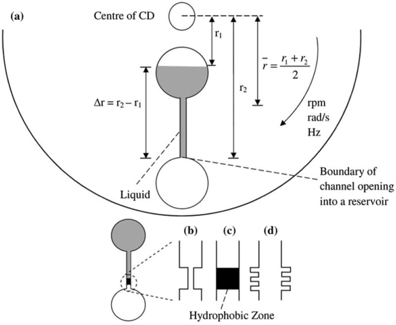
a The microfluidic CD with hydrophilic capillary valve, b hydrophobic valve with constriction, c hydrophobic valve with hydrophobic zone in an otherwise hydrophilic channel, d fishbone valve
Several mathematical models for describing passive valves are summarized in Table 1. While the 1D model describes capillary pressure in both, hydrophobic and hydrophilic valves, more complex 2D and 3D models address hydrophilic valves only [4, 16, 24]. Numerous variations of these 1D, 2D, and 3D models include modified 1D equations that consider the capillary pressure difference at the inlet and outlet of a channel [30, 32], modified 1D equations that take into account the heterogeneity of the channel surfaces [3, 8, 20, 22], and models that include the channel opening wedge angle β in the 1D equation [7, 11].
Table 1.
1D, 2D and 3D models for burst frequencies
| Model | Equation | Notes | |
|---|---|---|---|
| 1D [16] |
|
Describes the pressure in a capillary channel. (Refer to “Capillary” in Fig. 2) | |
| 2D [24] |
|
Describes the pressure when liquid begins to expand beyond the opening of the end of a channel (Refer to Stage 3 in Fig. 2) | |
| 3D [4] |
|
Describes the pressure when liquid begins to expand beyond the opening of the end of a channel (Refer to Stage 3 in Fig. 2) |
D is the diameter of a circular channel, D is substituted with the hydraulic diameter, Dh for a channel of any other shape, θc is the contact angle of liquid on solid (channel surface), γla is the liquid surface energy in contact with air, hn is the height of the channel, w and h are the width and height of the channel, β is the opening angle of the channel expansion
The present analysis will concentrate on the analysis of the models of hydrophilic passive valves. The meniscus propagation in hydrophilic (capillary) valve can be separated into four distinct phases: capillary flow is stopped at the channel opening (1), the fluid movement is resumed under the increased force (2), the concave meniscus becomes convex (3), and then it expands and finally bursts (4).
2 Methods
2.1 Burst frequency fundamentals
The underlying and common principle in all of the aforementioned models is the balancing between the centrifugal pressure and capillary pressure. The centrifugal pressure is due to the rotation of the CD and is given as
| (1) |
where ρ is the density of the liquid, ω is the rotational speed of the CD in radians per second (rads−1), Δr is the difference between the top and bottom of the liquid levels at rest with respect to the center of the CD, and r̄ is the average distance of the liquid from the centre of the CD (Fig. 1).
For the liquid meniscus to move in hydrophilic channel towards the center of the disc, the capillary pressure in the channel/valve must overcome the centrifugal pressure. This point of pressure equilibrium (termed the burst pressure in this study) depends on the geometry of the channel (including opening of the channel into a wider reservoir).
For any solid–liquid-air system, the capillary pressure can be derived from the change of total interfacial energy of the solid–liquid-air system, UT, with respect to the injected liquid volume, V:
| (2) |
The total interfacial energy of the system can be expressed as [31]
| (3) |
where Asl, Asa, Ala are the solid–liquid, solid-air, and liquid–air interface areas, and γsl, γsa, γla are the corresponding surface energies per unit area.
The above equation can be simplified by applying Young’s equation:
| (4) |
where U0 is a constant term given by (Asl + Asa)γsa, and is a constant energy component due to the sum of the solid–liquid and solid-air interfaces [4], and θc is the contact angle of the liquid with the solid channel wall. θc is greater than 90° for a hydrophobic material, and less than 90° for a hydrophilic material.
The capillary pressure can then be expressed as
| (5) |
Since dU0/dV = 0 (U0 is a constant); and dAla/dV = 0 (Ala, the surface boundary between liquid and the air in a capillary channel, does not change as long as the liquid is still traveling within the channel) [4, 6], Eq. (5) simplifies to
| (6) |
To calculate the burst angular velocity of a capillary valve on a microfluidic CD, the centrifugal pressure (Eq. 1) must be equated to the capillary pressure defined by Eq. 6. Thus burst angular velocity (in terms of rotations per minute “rpm”) can be expressed as
| (7) |
2.2 The capillary pressure within a capillary channel
In order to determine the capillary pressure within a capillary channel, we need to evaluate dAsl/dV for that specific channel. For a circular capillary with diameter D, the surface boundary between the solid and liquid, and the volume of the liquid are given as
| (8) |
| (9) |
where x is the length of liquid progression in the channel with respect to an arbitrary reference point. Similarly for a rectangular capillary of width w, and height h, the surface boundary and the volume of the liquid are given as
| (10) |
| (11) |
The value of dAsl/dV can then be expressed as
| (12) |
where Dh is the hydraulic diameter and is equal to D for a circular capillary. For a rectangular channel
| (13) |
Applying Eq. (6) gives us the general expression for the capillary pressure as
| (14) |
Alternatively, for a rectangular capillary, applying Eq. (13) gives
| (15) |
Equations (14) and (15) describe the pressure needed to move a liquid column in a channel from its resting position towards the outer edge of a CD. The angular velocity to initiate capillary flow is given by Eq. (7) above.
2.3 The burst pressure at the boundary of a hydrophilic channel opening into a reservoir
Various stages of the fluid dynamics prior to bursting from a channel into a reservoir are analyzed in this paper following Chen et al.’s [4] model for hydrophilic valves (Fig. 2). The channel has an opening wedge angle β, a cross section of height h and width w, and the fluid moves from an arbitrary reference point to a length L (Fig. 2). The fluid meniscus is characterized by assuming partial circular arcs with angles 2αh and 2αw. The angles αh and αw are secondary variables that facilitate the derivation of the burst pressure at the channel opening. These parameters are derived from primary parameters such as the contact angle θc and/or opening wedge angle β (Fig. 3).
Fig. 2.
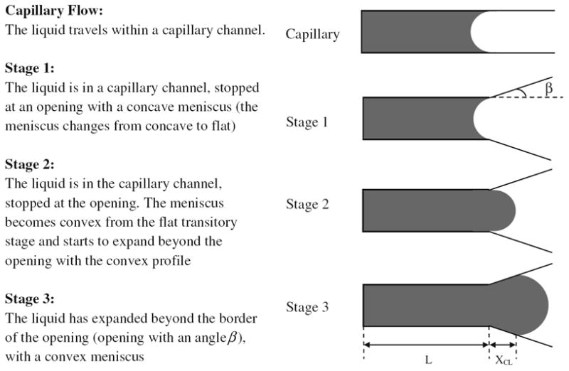
Liquid under capillary flow condition and in various pre-burst conditions (Stage 1, 2 and 3). β is the wedge angle of the channel opening, L is the length of liquid progression in the channel with respect to an arbitrary reference point, and XCL denotes the progress of liquid beyond the channel opening
Fig. 3.
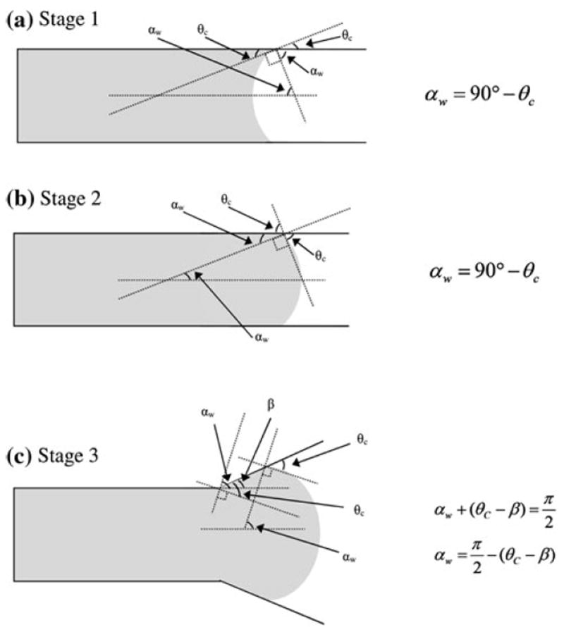
Geometry of meniscus angle for various stages of pre-burst a Stage 1, b Stage 2, and c Stage 3
2.3.1 Stage 1
In Stage 1 the fluid approaches the boundary of the hydrophilic channel opening with a concave meniscus. The total interfacial energy of the system UT, and the volume of the liquid V, for this stage can be expressed as
| (16) |
| (17) |
Chen et al. [4] proposed that the burst pressure can be approximated by simplifying the meniscus dynamics, and assuming that the meniscus curvature in the height dimension is zero (i.e. assuming a 2D meniscus where the meniscus curvature in the height direction is ignored). This assumption requires the condition that the height of the channel is much greater than the width (h ≫ w).1 That assumption uses the geometrical relationships
| (18) |
and
| (19) |
where Rh and Rw are the radii of curvature of the meniscus for the two sides of the rectangular capillary.
Applying Eq. (2) we can derive Stage 1 pressure
| (20) |
Using the equality of αw = 90° − θc (as shown in Fig. 3a) the equation can be presented as
| (21) |
2.3.2 Stage 2
In Stage 2, the pressure increase causes the fluid meniscus to become convex. The minor change in fluid volume due to the meniscus change from concave to convex allows us to determine the transition pressure for Stage 2:
| (22) |
Applying the equality αw = 90° − θc (as shown in Fig. 3b) results in
| (23) |
2.3.3 Stage 3
In Stage 3 increasing the pressure further expands the fluid meniscus beyond the boundary at the channel opening while maintaining a convex meniscus (refer to the supplementary material for a detailed mathematical representation of the meniscus in the width dimension during this stage).
The total interfacial energy of the system, UT and the volume of the fluid, V for this stage can be expressed as
| (24) |
| (25) |
Applying Eq. (2) yields the burst pressure for Stage 3:
| (26) |
To simplify and evaluate this expression, XCL is set to zero (see Fig. 2), and the meniscus curvature in the height direction is ignored [4]. This simplification leads to
| (27) |
For specific designs where h ≫ w Eq. (27) simplifies further to
| (28) |
Applying the condition of β = αw, Eq. (27) becomes
| (29) |
Further using the h ≫ w assumption leads to the final equation for burst pressure:
| (30) |
2.4 Experimental setup and materials
Experimental work was carried out on a custom-made CD spin test system. The system incorporates a laser rpm counter and high-speed camera attached to a computer for data recording. The microfluidic CDs are tested using a mixture of deionized water with red dye (at ratio of 1 part dye to 10 part water) in the experiments. For each experimental work, a total of 10 CDs were fabricated and tested for consistency.
The microfluidic CDs are fabricated from layers of polymethyl methacrylate (PMMA) plastic and a custom-manufactured pressure-sensitive adhesive (PSA) (by FLEXcon, USA). Each CD consists of three layers: two layers of PMMA bound with a layer of PSA (see Fig. 4). A computer numerical control (CNC) machine (model Vision 2525, by Vision Engraving & Routing Systems, USA) is utilized to machine the microfluidic features in the PMMA layers, and a digitally controlled cutting plotter machine (model PUMA II, by GCC, Taiwan) is used to cut the microfluidic features in the PSA layer. The three layers are then aligned and bound together using a custom made press-roller system.
Fig. 4.
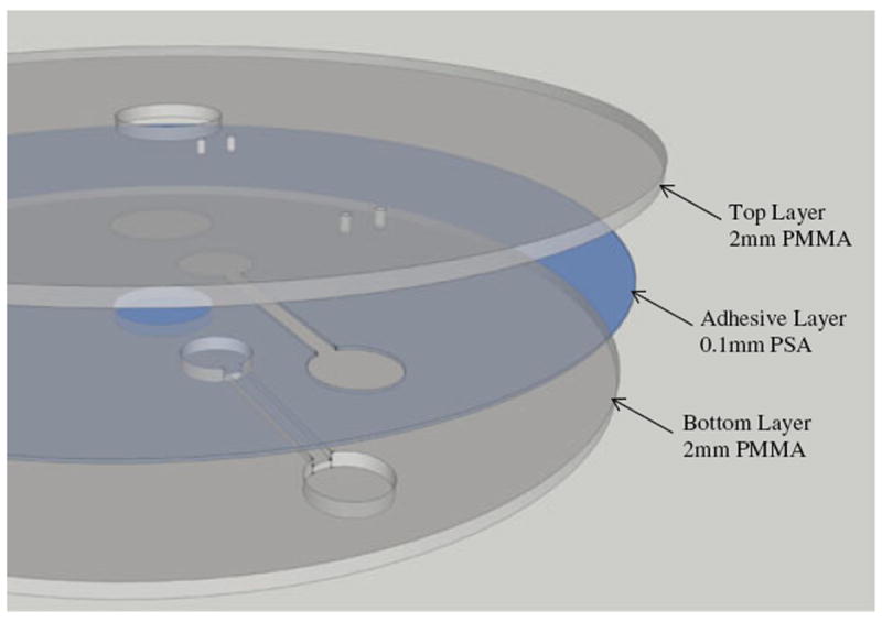
Assembly of the Microfluidic CD
3 Results
In the following, we discuss parameters that are known to affect the magnitude of the burst pressure, such as the hydraulic diameter Dh, the height h and the width w of the channel, and the channel opening wedge angle β. Parameters such as surface tension, γla, and fluid density, ρ, are based on standard values for water at room temperature: 71.97 mN/m and 1,000 kg/m3, respectively, while the contact angle θc for PMMA is measured with DataPhysics Instruments GmbH OCA Machine as 78°. The distance from the top of liquid level in the reservoir to the centre of CD r1, and the distance from the liquid meniscus in the channel to the centre of CD r2 (see Fig. 1) are 27.6 and 31 mm, respectively. The capillary pressure, Stage 1 pressure, Stage 2 pressure, and the burst pressure are evaluated using Eqs. (14), (21), (23) and (29), respectively. A compilation of the theoretical, experimental, and simulation results from the literature are also presented.
3.1 Channel hydraulic diameter
One of the most common CD design parameters is the hydraulic diameter, Dh, which is calculated from the height, h, and width, w, of the channel using Eq. (13). The chart of experimental and theoretical burst “rpm” calculated using Eqs. (7) and (14) versus hydraulic diameter is presented in Fig. 5.
Fig. 5.
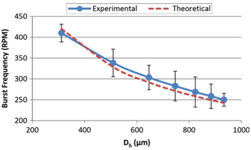
Burst frequency versus hydraulic diameter using Eq. (14) and experimental results (Dh = 300 to 900 μm, γla = 71.97 mN/m, ρ = 1,000 kg/m3, θc = 78°, r1, = 27.6 mm, r2 = 31 mm)
For comparison purposes, some results from the literature are summarized as follows:
Zeng et al. [30] showed that for a rectangular channel, the burst pressure increases when the hydraulic diameter is reduced from 250 to 36 μm. This translates to a decrease in burst “rpm” with an increase in hydraulic diameter.
Glière et al. [11] presented experimental and simulation results that show an increase in burst pressure (and thus increase in the burst “rpm”) as the hydraulic diameter is reduced. They also presented experimental results from Duffy et al. [10] that showed a similar trend.
Chew et al. [6] demonstrated that for circular channels of varying radii (from 140 to 1270 μm), the burst pressure (and consequently, burst “rpm”) decreases non-linearly with an increase in radius.
3.2 Channel height and width
The aspect ratio (AR) of a channel is typically expressed as the ratio of the channel height to its width, h/w. The Stage 1, and Stage 2 theoretical burst “rpm” are evaluated using Eqs. (7), (21) and (23) (for channels’ widths and heights in the range from 20 to 500 μm) and are summarized in Table 2. The chart of experimental and theoretical burst “rpm” using Eqs. (7) and (21) versus AR (for a fixed width of 700 μm, and channels’ heights ranging from 200 to 1,400 μm) is also presented in Fig. 6.
Table 2.
Fig. 6.
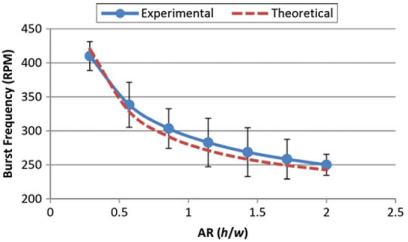
Theoretical burst frequency vs aspect ratio (h/w) using equation Eq. (21) and Experimental results (h = 200 to 1400 μm, w = 700 μm, γla = 71.97 mN/m, ρ = 1000 kg/m3, θc = 78°, r1, = 27.6 mm, r2 = 31 mm)
For comparison purposes, some results from the literature are summarized below:
In a study by Leu and Chang [19], results indicate that the absolute pressure (the calculated pressure is negative) required to burst the liquid changes as the aspect ratio (AR) of h/w changes. For AR < 1 (h is fixed at 30 μm, and w is varied from 30 to 300 μm), the absolute burst pressure (and thus burst “rpm”) increases as AR increases. For AR > 1 (h is varied from 30 to 300 μm, and w is fixed at 30 μm), absolute pressure decreases as AR increases. This translates to a decrease in the burst “rpm” as AR increases. The results show that the maximum burst “rpm” occurs when AR = 1 (h = w).
In a later study by Glière and Delattre [11], simulation of a rectangular channel (h is fixed at 15 μm, and w is varied from 30 to 115 μm) showed that pressure decreases (and the burst “rpm” decreases) as AR decreases from 0.5 to 0.13.
In experimental and theoretical work by Cho et al. [8], as the AR decreases from 10 to 1 (h is fixed at 150 μm, and w varies from 15 to 150 μm), the burst “rpm” decreases.
In a study by Chen et al. in 2007 [4], experimental work was carried out on rectangular channels (300 μm in width and of various heights). It was shown that the burst “rpm” increases as the AR increases from 0.42 to 2.0. In a comparison between the channel widths of 300 and 400 μm the study also showed that for an identical AR, the narrower channel requires higher burst “rpm”.
3.3 Channel opening wedge angle
Another important CD design parameter is the channel opening wedge angle β. Using Eq. (29), the burst “rpm” versus the opening wedge angle (with θc = 40°) is plotted in Fig. 7.
Fig. 7.
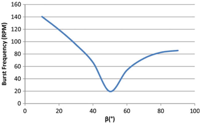
Burst frequency versus wedge angle (β) using Eq. (29) (h = 800 μm, w = 800 μm, γla = 71.97 mN/m, ρ = 1,000 kg/m3, θc = 40°, r1, = 36 mm, r2 = 48 mm, β = 10°–90°)
For comparison purposes, some results from the literature are summarized as follows:
In a study by Leu and Chang [19], experimental data and modelling results showed that absolute pressure increases non-linearly when β increases. This translates to an increase in burst “rpm” as β increases.
In two separate studies by Cho et al. in 2004 and 2007 [7, 8], the experimental results and theoretical calculations showed that the burst pressure and the corresponding “rpm” increase with an increase in the wedge angle β.
In a study by Chen et al. [4], the theoretical burst pressure for varying β values was presented. The study discussed that for β less than 50°, the fluid in the channel is moved forward by a positive capillary force. But as the β increases to values higher than 50°, the positive pressure goes to zero and consequently becomes negative. This negative pressure opposes the fluid flow and increases in magnitude with higher β values. This translates to a burst “rpm” that decreases for β less than 50° and then increases for β greater than 50°.
4 Discussion
4.1 1D, 2D, and 3D models
The simple 1D equation represents the capillary flow condition where theoretical model works for both, hydrophilic and hydrophobic channels. For example, Eq. (14) will work for wetting angles both, greater or less than 90° (hydrophilic and hydrophobic channels, correspondingly), but for hydrophobic channels the sign of the pressure would be negative as cos θc will be negative.
The 2D model was developed to represent Stage 3 with the inclusion of the wedge angle β parameter [24]. However, the 2D model imposes two restrictions. The first restriction is that the channel height, h, must be much greater than the channel width, w, which is not always the case. The second restriction is that XCL is assumed to be 0 (see Fig. 2).
The 3D model was developed as an attempt to further supplement the 2D model by considering meniscus curvature in both directions [4]. However, the present 3D model has limitations. While the 3D model applies the angle geometry of the fluid meniscus from Stage 3 (convex meniscus), the equation itself is derived based on the fluid condition in Stage 1 (with concave meniscus).
Neither the 2D nor the 3D models represent the Stage 3 accurately, where the pressure reaches its peak just prior to bursting.
4.2 Stage 1, Stage 2, and Stage 3 equations
Our Stage 2 equation (Eq. 22) is similar to corresponding equation (Eq. 15) in Chen et al.’s [4]. However, Chen et al.’s Eq. 15 uses a concave meniscus instead of a convex meniscus. Thus in Chen et al.’s Eq. 15 the sign before the “sin αw” should be a minus sign to reflect the convex meniscus in Stage 2. The corresponding Stage 1 and 2 equations in present analysis (Eqs. 20, 22, respectively) are implemented with the correct sign.
Our Stage 3 equation (Eq. 27) is similar to Chen et al.’s Eq. 20 which they meant to represent Stage 3 with [4]. However, Chen et al.’s Eq. 20 uses a concave meniscus instead of a convex meniscus. Note that the sign mistake in various parts of their Eq. 20 is due to applying the wrong meniscus orientation.
For specific cases where h ≫ w, our Stage 3 equation (Eq. 28) matches the 2D model presented by Man et al. [24]. However, this model does not truly represent the conditions in the Stage 3 due to a few discrepancies. The first is the XCL = 0 condition that describes a meniscus that fits Stage 2, and not Stage 3 conditions. The second is the assumption that disregards the meniscus height.
Our burst pressure equation (Stage 3) (Eq. 29) differs from the 3D model of Chen et al.’s Eq. 19 [4]. The reason for the difference is due to the incorrect derivation of the 3D model by substituting the Stage 3 angle equality αw = 90° − (θc − β) (Fig. 3c) into the Stage 1 equation (Eq. 20) (which was incorrectly presented as the Stage 2 equation by Chen et al.).
Overall the Stage 1, 2 and 3 equations attempt to describe the burst pressure of the fluid just prior to the bursting. However, many assumptions have introduced inaccuracies in derivation of these expressions:
The effect of the meniscus change in the height dimension is disregarded.
The meniscus is assumed to take on a perfectly circular arc shape. This assumption imposes the condition that αw = 90° − θc for the Stage 1 and Stage 2, and αw = 90° − (θc − β) for the Stage 3. Furthermore, should the top, bottom and side surfaces of the channel are composed of different materials, the meniscus shape may not be symmetrical.
XCL is set to zero to derive the equation for the Stage 3. This effectively forces the fluid back to the Stage 2 conditions.
The mathematical representation of the meniscus geometry in the Stage 3 results in β = αw. This contradicts with the angle geometry imposed by assumption 2 listed above.
h ≫ w assumption applies only to a limited number of cases.
4.3 Effects of Dh, AR (h/w), and β
As shown in Fig. 5, the burst “rpm” decreases non-linearly when the hydraulic diameter of the channel, Dh increases. This result is in agreement with the results from the literature by Zeng et al. [30], Glière et al. [11], and Chew et al. [6].
The results in Table 2 indicate that using the Stage 1 equation (Eq. 21), the burst “rpm” decreases with increasing AR when height, h, is varied (case I and IV), and the burst “rpm” increases with increasing AR when width, w, is varied (case II and III). When compared with the results from the literature, Leu and Chang’s [19] results match those of case III for AR < 1, and case IV for AR > 1; Glière and Delattre’s [11] results match that of case III for AR < 1 (for increasing trend); while Cho et al.’s [8] results match that of case II. However, Chen et al.’s [4] results do not match any of the cases in Table 2. It is further observed that while Glière and Delattre’s [11] results agree with Leu and Chang’s [19] findings for the case of AR < 1, Cho et al.’s [8] result contradicts with Leu and Chang’s [19] findings for AR > 1. The difference between Cho et al.’s [8] and Leu and Chang’s [19] results for AR > 1 is due to the former applying a fixed width and the later applying a fixed height, respectively. These findings depict the inconsistencies about the effect of channel dimensions on the burst pressure in the microfluidic domain.
As shown in Fig. 6, for a fixed width of 700 μm, and channels’ heights ranging from 200 to 1,400 μm, the experimental burst “rpm” decreases with an increase in AR. This agrees with the theoretical result shown in Table 2 (for case I and IV using Eq. 21).
The results in Table 2 further shows that using the Stage 2 equation Eq. (23) for a fixed width, the burst “rpm” decreases for AR < 1 (case I) and increases for AR > 1 (case IV) with respect to an increasing AR. For a fixed height, the burst “rpm” increases for AR > 1 (case II), and decreases for AR < 1 (case III) with respect to an increasing AR. Compared with the literature, Leu and Chang’s [19] results show opposite trend to those of case III and IV. The results from Glière and Delattre [11] also show no match. However, Cho et al.’s [8] results match those of case II and Chen et al.’s [4] match those of case IV for AR > 1, but for AR < 1 the results show an opposite trend compared with case I.
As shown in Fig. 7, with an increase in the wedge angle β of the channel opening, the burst “rpm” decreases when β is less 50°, and increases when β is greater than 50°. The result in Fig. 7 is not comparable to the results from Leu and Chang [19] and Cho et al. [7, 8], but is in agreement with Chen et al.’s [4] where increasing wedge angles results in negative pressure values representing the pressure that opposes the fluid flow. It is noted that the direct comparison of results with the literature is difficult due to the variety in conclusions with regard to the effects of β with respect to the rotational speed [4, 8], pressure sign (positive [7], or negative [19]), and a combination of both positive and negative pressures [4].
The findings above indicate that the literature contains varying results for the effects of the aspect ratio (h/w) and the wedge angle β for comparison. It is also observed that there is a need to determine a standard method for presenting and interpreting the effect of the wedge angle β on the burst pressure.
4.4 Summary
The theoretical development of the burst frequency equations for capillary valves on the microfluidic CD has been presented. We have defined and presented the capillary fluid flow and the pre-burst equations by analyzing the menisci dynamics in four different stages (with respect to θC, β, αw, and αh). Inconsistencies, limitations and errors in the various models from the literature are also highlighted. The derived equations have also been validated through comparison with experimental and theoretical results from the literature.
While present study concentrates on the theoretical analysis of the burst pressure for hydrophilic passive valves, our future work will address challenges of theoretical predictions of the burst pressure for passive valves.
Supplementary Material
Acknowledgments
This research is financially supported by University of Malaya, Ministry of Higher Education High Impact Research (UM/HIR/MOHE/ENG/05), and University of Malaya Research Grant (UMRG: RG023/09AET).
The first author would like to thank Chua Huang Shen for participating in the initial study of the mathematical models, and Chung Wei Ning, Tiffany for the compilation of the various mathematical models from the literature.
MM, SS and LK would like to acknowledge support of the National Institute of Health (grant 1 R01 AI089541-01). MM also acknowledges support of WCU (World Class University) program (R32-2008-000-20054-0) through the National Research Foundation of Korea funded by the Ministry of Education, Science and Technology.
Footnotes
It should be noted that for the rectangular cross-section we termed the smaller side of the channel “the width”.
Electronic supplementary material The online version of this article (doi:10.1007/s11517-012-1020-7) contains supplementary material, which is available to authorized users.
Contributor Information
Tzer Hwai Gilbert Thio, Medical Informatics and Biological Micro-electro-mechanical Systems (MIMEMS) Specialized Laboratory, Department of Biomedical Engineering, Faculty of Engineering, University of Malaya, 50603 Kuala Lumpur, Malaysia.
Salar Soroori, Medical Informatics and Biological Micro-electro-mechanical Systems (MIMEMS) Specialized Laboratory, Department of Biomedical Engineering, Faculty of Engineering, University of Malaya, 50603 Kuala Lumpur, Malaysia; Department of Biomedical Engineering, University of California, Irvine, Irvine 92697, USA.
Fatimah Ibrahim, Email: fatimah@um.edu.my, Medical Informatics and Biological Micro-electro-mechanical Systems (MIMEMS) Specialized Laboratory, Department of Biomedical Engineering, Faculty of Engineering, University of Malaya, 50603 Kuala Lumpur, Malaysia.
Wisam Al-Faqheri, Medical Informatics and Biological Micro-electro-mechanical Systems (MIMEMS) Specialized Laboratory, Department of Biomedical Engineering, Faculty of Engineering, University of Malaya, 50603 Kuala Lumpur, Malaysia.
Norhayati Soin, Medical Informatics and Biological Micro-electro-mechanical Systems (MIMEMS) Specialized Laboratory, Department of Biomedical Engineering, Faculty of Engineering, University of Malaya, 50603 Kuala Lumpur, Malaysia; Department of Electrical Engineering, Faculty of Engineering, University of Malaya, 50603 Kuala Lumpur, Malaysia.
Lawrence Kulinsky, Department of Mechanical and Aerospace Engineering, University of California, Irvine, Irvine 92697, USA.
Marc Madou, Medical Informatics and Biological Micro-electro-mechanical Systems (MIMEMS) Specialized Laboratory, Department of Biomedical Engineering, Faculty of Engineering, University of Malaya, 50603 Kuala Lumpur, Malaysia; Department of Biomedical Engineering, University of California, Irvine, Irvine 92697, USA; Department of Mechanical and Aerospace Engineering, University of California, Irvine, Irvine 92697, USA; Ulsan National Institute of Science and Technology (UNIST), World Class University (WCU), Ulsan, South Korea.
References
- 1.Abi-Samra K, Hanson R, Madou M, Gorkin RA., III Infrared controlled waxes for liquid handling and storage on a CD-microfluidic platform. Lab Chip. 2011;11:723–726. doi: 10.1039/c0lc00160k. [DOI] [PubMed] [Google Scholar]
- 2.Amasia M, Cozzens M, Madou MJ. Centrifugal microfluidic platform for rapid PCR amplification using integrated thermoelectric heating and ice-valving. Sens Actuator B Chem. 2012;161:1191–1197. [Google Scholar]
- 3.Andersson H, Van der Wijngaart W, Griss P, Niklaus F, Stemme G. Hydrophobic valves of plasma deposited octafluorocyclobutane in DRIE channels. Sens Actuator B Chem. 2001;75:136–141. [Google Scholar]
- 4.Chen JM, Huang PC, Lin MG. Analysis and experiment of capillary valves for microfluidics on a rotating disk. Microfluid Nanofluid. 2008;4:427–437. [Google Scholar]
- 5.Chen QL, Cheung KL, Kong SK, Zhou JQ, Kwan YW, Wong CK, Ho HP. An integrated lab-on-a-disc for automated cell-based allergen screening bioassays. Talanta. 2012;97:48–54. doi: 10.1016/j.talanta.2012.03.061. [DOI] [PubMed] [Google Scholar]
- 6.Chew M, Teo W, Xie L, Premachandran CS, Wong WH, Xu D, Yao Q. Study of a capillary force driven passive valve for a microfluidic package; Proceedings of the 8th electronics packaging technology conference 2006, EPTC ’06; Singapore. Institute of Electrical and Electronics Engineers (IEEE); 2006. pp. 448–453. [DOI] [Google Scholar]
- 7.Cho H, Kim HY, Kang JY, Kim TS. Capillary passive valve in microfluidic systems; Technical proceedings of the 2004 NSTI nanotechnology conference and trade show—NSTI Nanotech 2004; Boston, Massachusetts . Nano Science and Technology Institute (NSTI); 2004. pp. 263–266. [Google Scholar]
- 8.Cho H, Kim HY, Kang JY, Kim TS. How the capillary burst microvalve works. J Colloid Interface Sci. 2007;306:379–385. doi: 10.1016/j.jcis.2006.10.077. [DOI] [PubMed] [Google Scholar]
- 9.Ducrée J, Haeberle S, Lutz S, Pausch S, Von Stetten F, Zengerle R. The centrifugal microfluidic bio-disk platform. J Micromech Microeng. 2007;17:S103–S115. [Google Scholar]
- 10.Duffy DC, Gillis HL, Lin J, Sheppard NF, Jr, Kellogg GJ. Microfabricated centrifugal microfluidic systems: characterization and multiple enzymatic assays. Anal Chem. 1999;71:4669–4678. [Google Scholar]
- 11.Glière A, Delattre C. Modeling and fabrication of capillary stop valves for planar microfluidic systems. Sens Actuator A. 2006:130–131. 601–608. [Google Scholar]
- 12.Gorkin R, Nwankire CE, Gaughran J, Zhang X, Donohoe GG, Rook M, O’Kennedy R, Ducrée J. Centrifugo-pneumatic valving utilizing dissolvable films. Lab Chip. 2012;12:2894–2902. doi: 10.1039/c2lc20973j. [DOI] [PubMed] [Google Scholar]
- 13.Gorkin R, Soroori S, Southard W, Clime L, Veres T, Kido H, Kulinsky L, Madou M. Suction-enhanced siphon valves for centrifugal microfluidic platforms. Microfluid Nanofluid. 2012;12:345–354. [Google Scholar]
- 14.He H, Yuan Y, Wang W, Chiou Nan-Rong NR, Epstein AJ, Lee LJ. Design and testing of a microfluidic biochip for cytokine enzyme-linked immunosorbent assay. Biomicrofluidics. 2009;3:022401. doi: 10.1063/1.3116665. [DOI] [PMC free article] [PubMed] [Google Scholar]
- 15.Ibrahim F, Nozari AA, Jahanshahi P, Soin N, Rahman NA, Dawal SZM, Kahar MKBA, Samra KA, Madou M. Analysis and experiment of centrifugal force for microfluidic ELISA CD platform. Biomedical engineering and sciences (IECBES), 2010 IEEE EMBS conference; 2010. pp. 466–470. [Google Scholar]
- 16.Kim J, Kido H, Rangel RH, Madou MJ. Passive flow switching valves on a centrifugal microfluidic platform. Sens Actuator B Chem. 2008;128:613–621. [Google Scholar]
- 17.Lai S, Wang S, Luo J, Lee LJ, Yang ST, Madou MJ. Design of a compact disk-like microfluidic platform for enzyme-linked immunosorbent assay. Anal Chem. 2004;76:1832–1837. doi: 10.1021/ac0348322. [DOI] [PubMed] [Google Scholar]
- 18.Lee BS, Lee JN, Park JM, Lee JG, Kim S, Cho YK, Ko C. A fully automated immunoassay from whole blood on a disc. Lab Chip. 2009;9:1548–1555. doi: 10.1039/b820321k. [DOI] [PubMed] [Google Scholar]
- 19.Leu TS, Chang PY. Pressure barrier of capillary stop valves in micro sample separators. Sens Actuator A. 2004;115:508–515. [Google Scholar]
- 20.Li G, Chen Q, Li J, Hu X, Zhao J. A compact disk-like centrifugal microfluidic system for high-throughput nanoliter-scale protein crystallization screening. Anal Chem. 2010;82:4362–4369. doi: 10.1021/ac902904m. [DOI] [PubMed] [Google Scholar]
- 21.Lin SIE. Parametric analysis of a novel semi-circular microfluidic CD-ELISA valve. J Biol Eng. 2011;5:1–13. doi: 10.1186/1754-1611-5-15. [DOI] [PMC free article] [PubMed] [Google Scholar]
- 22.Lu C, Xie Y, Yang Y, Cheng MMC, Koh CG, Bai Y, Lee LJ, Juang YJ. New valve and bonding designs for microfluidic biochips containing proteins. Anal Chem. 2007;79:994–1001. doi: 10.1021/ac0615798. [DOI] [PubMed] [Google Scholar]
- 23.Madou M, Zoval J, Jia G, Kido H, Kim J, Kim N. Lab on a CD. Annu Rev Biomed Eng. 2006;8:601–628. doi: 10.1146/annurev.bioeng.8.061505.095758. [DOI] [PubMed] [Google Scholar]
- 24.Man PF, Mastrangelo CH, Burns MA, Burke DT. Microfabricated capillarity-driven stop valve and sample injector; Proceedings of the eleventh annual international workshop on micro electro mechanical systems 1998, MEMS 98; Heidelberg, Germany. Institute of Electrical and Electronics Engineers(IEEE); 1998. pp. 45–50. [DOI] [Google Scholar]
- 25.Messinger RJ. Honor thesis. Ohio State University; Columbus: 2006. Microfluidics: mathematical modeling and empirical analysis of the burst frequencies of a novel fishbone capillary valve and the development of an algorithm to calculate its hold time. [Google Scholar]
- 26.Peyman J, Nozari AA, Soin N, Ibrahim F. Evaluation of pressure changes for capillary and fishbone valves in lab-on-CD systems. Proceedings of international conference for technical postgraduates (TECHPOS) 2009; Kuala Lumpur. Institute of Electrical and Electronics Engineers (IEEE); 2009. pp. 1–5. [DOI] [Google Scholar]
- 27.Pitchaimani K, Sapp BC, Winter A, Gispanski A, Nishida T, Hugh Fan Z. Manufacturable plastic microfluidic valves using thermal actuation. Lab Chip. 2009;9:3082–3087. doi: 10.1039/b909742b. [DOI] [PubMed] [Google Scholar]
- 28.Thio T, Nozari AA, Soin N, Kahar MKBA, Dawal SZM, Samra KA, Madou M, Ibrahim F. In: Osman N, Abas W, Wahab A, Ting H-N, editors. Hybrid capillary-flap valve for vapor control in point-of-care microfluidic CD; 5th Kuala Lumpur international conference on biomedical engineering 2011; Heidelberg: Springer; 2011. pp. 578–581. [Google Scholar]
- 29.Yusoff NA, Soin N, Ibrahim F. Lab-on-a-disk as a potential microfluidic platform for dengue NS1-ELISA. Proceedings of IEEE symposium on industrial electronics & applications(ISIEA) 2009; Kuala Lumpur. Institute of Electrical and Electronics Engineers (IEEE); 2009. pp. 946–950. [DOI] [Google Scholar]
- 30.Zeng J, Banerjee D, Deshpande M, Gilbert JR, Duffy DC, Kellogg GJ. Design analyses of capillary burst valves in centrifugal microfluidics. micro total analysis systems 2000; Proceedings of the uTAS 2000 symposium; Enschede, The Netherlands. 2000. pp. 579–582. [Google Scholar]
- 31.Zeng J, Deshpande M, Greiner KB, Gilbert JR. Fluidic capacitance model of capillary-driven stop valves. MEMS proceedings 2000 ASME international mechanical engineering congress and exposition (IMECE’00); Orlando. 2000. [Google Scholar]
- 32.Zoval JV, Madou MJ. Centrifuge-based fluidic platforms. Proc IEEE. 2004;92:140–153. [Google Scholar]
Associated Data
This section collects any data citations, data availability statements, or supplementary materials included in this article.


