Abstract
This paper presents the design and test of a dual-mode electric and magnetic biological stimulator (EM-Stim). The stimulator generates pulsing electric and magnetic fields at programmable rates and intensities. While electric and magnetic stimulators have been reported before, this is the first device that combines both modalities. The ability of the dual stimulation to target bone and muscle tissue simultaneously has the potential to improve the therapeutic treatment of osteoporosis and sarcopenia. The device is fully programmable, portable and easy to use, and can run from a battery or a power supply. The device can generate magnetic fields of up to 1.6 mT and output voltages of +/−40 V. The EM-Stim accelerated myogenic differentiation of myoblasts into myotubes as evidenced by morphometric, gene expression, and protein content analyses. Currently, there are many patents concerned with the application of single electrical or magnetic stimulation, but none that combine both simultaneously. However, we applied for and obtained a provisional patent for new device to fully explore its therapeutic potential in pre-clinical models.
Keywords: Electrical stimulation, magnetic stimulation, microcontrollers, embedded software, switched-mode power supply, muscle cells, protein synthesis, C2C12 myoblasts, C2C12 myotubes, myogenesis, myogenic differentiation, proliferation, cell area, muscle wasting, sarcopenia
INTRODUCTION
Pulsed electrical stimulation has been extensively employed in muscle stimulation particularly in patients with neuromuscular impairments [1] with the aim that full or partial mobility of limbs can be restored. This type of stimulation is commonly known as functional electrical stimulation or FES. Electrical stimulation has also been used in electro-tactile stimulation to evocate tactile sensation by applying a local electric current through the skin [2] and in stem cell differentiation of muscle cells [3]. Other applications include pain relieving, muscle strengthening, cardiac pacing, and iontophoretic drug delivery [4, 5]. Several electrical stimulators have been reported in the literature and some are available commercially [1, 6–7, 8–12].
On the other hand, magnetic stimulation has been explored in areas ranging from bone repair, osteoporosis, arthritis, pain relieving, psychiatric disorders, brain stimulation and cancer treatment [13, 14]. In magnetic stimulation a sequence of current pulses is applied to a coil which generates corresponding magnetic pulses. The pulse repetition frequency is usually very low (6 Hz to 500 Hz). Magnetic stimulation is especially popular in brain stimulation where detectable physiological and behavioral effects both in humans and in animals have been observed [15]. Another common use of magnetic stimulation is in the treatment of bone conditions such as non-union fractures, failed joint fusions, and congenital pseudoarthroses with success rates of 70% to 95% in double-blind studies [16]. Biological magnetic stimulators for brain and bone stimulation are commercially available [16–20]. Although electrical and magnetic stimulation have been shown to produce quantifiable effect on living organisms, their joint application has not been fully explored and exploited.
In a human or animal body, muscles and bones are intimately interrelated and the loss of function in one has the potential to affect the other. This interrelation is especially evident in persons with bone fractures. While the bone is healing, the muscles lose mass due to the lack of exercise. Furthermore, when skeletal muscles are not exercised, bone mass density decreases. It is very common for sarcopenia and ostestoporosis to manifest as twin diseases. In these situations, muscle mass can be partially maintained if externally stimulated by applying repetitive electric pulses while magnetic pulses can be successfully employed in bone healing. In this paper we present a dual-mode electric and magnetic stimulator prototype that exploits this muscle-bone interrelation to speed up recovery from fractures or muscle mass loss. The proposed device, that we call EM-Stim, has been designed to generate electric pulses of different frequencies to electrically stimulate muscle cells to promote muscle cell growth. It also generates magnetic pulses of variable duration and intensities that can be used to stimulated bone cells and promote their growth. This dual stimulation is a unique feature of the EM-Stim and makes it a promising device in the treatment of bone fractures or muscle injuries. Besides this clinical application, the EM-Stim is being used to study the crosstalk at the cellular level between muscle and bone. At the cellular level, this device will be used to better understand the interplay between bone and muscle cells. Ultimately, our goal is to test this device in animals and humans to fully realize its potential on musculoskeletal injuries and bone and muscle diseases, particularly osteoporosis and sarcopenia, two diseases that are becoming a serious health care concern for industrialized nations.
The rest of this paper is organized as follows: Background presents a literature review of previously reported stimulators. It also discusses the physical principles exploited in electrical and magnetic stimulation and related patents. The next section presents the circuit design of the proposed dual-mode stimulator. Then, the measurements characterizing the outputs of the device and the results of in-vitro stimulation of muscle cells are shown. The last section concludes the paper.
BACKGROUND
Literature Review
A programmable electronic stimulator FES was presented in [10]. The stimulator is programmable, has four output channels and is battery operated. It is able to generate mono-phasic electric pulses of up to 150 V by employing a flyback power converter. The output stage is an optically isolated push-pull circuit. It also has synchronization input and outputs for cascading with other devices. A specially developed computer program running on Windows operating system is required to program the parameters of the stimulator. The programming is performed through a serial port.
A programmable ramp waveform generator for pulsed electromagnetic field (PEMF) stimulation was designed in [11]. The waveform generator is implemented around the ATMEGA 168 microcontroller which generates pulses with selectable duty cycle that are integrated by an integrator circuit to produce ramp waveforms. The slope of the ramp waveform is controlled by the microcontroller through a digital potentiometer. The slope is set according to the desired magnetic field settings. This generator is intended to work with a coil driver to produce a time-varying magnetic field. Two coils of radius 4.25 cm and 6 cm and a number of turns of 120 and 230 respectively were built to cover the targeted field intensity range (0.5 mT to 4.5 mT).
A high-efficiency circuit for electrical muscle stimulation was reported in [12]. The circuit is based on a boost converter topology in which the reference voltage is a square waveform instead of a constant voltage. By virtue of the feedback loop of the boost converter, a high voltage waveform that follows the shape of the low-voltage square reference voltage is generated. This set up allows reaching efficiencies of up to 98.6%.
In [1] a multichannel direct-synthesized electrical stimulator is described. It introduces an element-envelope method for flexible waveform generation. The method is implemented with the digital signal processor TMS320C32. The signal processor also handles the serial communication with a host computer. The generated waveforms are applied to a constant-current output stage. The employed constant-current source is based on the Holland architecture with a Wilson mirror and is able to provide a linear voltage-to-current conversion with high-voltage compliance. A custom Windows-based program was developed to communicate with the stimulator.
Two circuits for FES are described in [21]. The first circuit is based on an oscillator that generates a train of pulses with controlled amplitude, frequency, and pulse width. These pulses are stepped up to the required output voltage by a transformer. The second circuit is based on a resonant converter. The resonant converter is composed of two transistors, a capacitor, and an inductor. The authors conclude that a stimulator based on the resonant converter results in a more compact circuit since no transformer is needed.
A high-voltage constant current stimulator for electrotactile stimulation is described in [2]. The stimulator is based on an improved Holland current pump topology in a bridge configuration to allow high impedances and small currents. A compliance voltage of almost 800 V was achieved using commercially available high-voltage op-amps (Apex PA-85A). A high power supply of +/−430 V was obtained by stacking two 200 V and two 230 V floating supplies. This setup created a common mode latch-up problem. The latch-up problem was averted using high-voltage relays that kept the supplies disconnected until 1 s after power up.
Another programmable electric stimulator for skeletal muscle cardiac assist is reported in [22]. It is built around the MC68HC811 microcontroller which sends the control signals to the analog electronics to generate the desired pulse sequence. It also interfaces with a custom Windows-based program for interaction with the user and to rapidly develop new stimulation sequences. The analog electronics is essentially an R-2R digital-to-analog converter implemented with commercially available op-amps. A boost DC-DC converter based on the MAX633 regulator was employed to generate a voltage +/−15 V to power up the analog part from a 5 V supply.
Interaction between Electro-Magnetic Fields and Cells
Two mechanisms are believed to produce a biophysical response. The first mechanism considers the electric field induced by the time-varying magnetic field. This electric field moves free charges in both the intracellular and extracellular spaces polarizing the cell membranes. This is the same mechanism that electrical stimulation exploits [23]. The other mechanism considers the interaction of the applied magnetic field with the magnetic moments produced by a nucleus, atom or molecule [24]. It is suggested that the magnetic fields are detected by magnetic molecular dipoles [25]. Magnetic fields have been show for example to influence the behavior of free radicals in proteins and DNA environments, which in turn could have biological effects.
Importantly, magnetic stimulation has been shown to be especially effective in the treatment of non-union bone fractures, failed joint fusions and congenital pseudoarthroses with success rates between 70%–90% [14]. Pulsed magnetic stimulation has been shown to stimulate calcification of the fibrocartilage and to increase blood flow due to the effects on ionic calcium channels. Another mechanism that is thought to take place is through the influence of the pulsed magnetic field on the rate of formation by osteoblasts [26], which might help explain the faster healing times.
REVIEW OF PATENTS
Intramuscular Stimulation Therapy Using Localized Electrical Stimulation
(Patent# 6058938/Jennifer Chu et al./ Jan 23, 1998)
This patent is an application of a modality of electrical twitch-obtaining intramuscular stimulation (ETOIS) pain relief therapy through inducing local and focal stimulation to muscle motor end plate zones or regions of adjacent motor end plate zones. The electrical stimulation facilitates the elicitation of strong twitch responses from muscle fibers associated with the stimulated motor end plates, generally without requiring physical needle manipulation following the initial pin insertion. ETOIS induces muscle discharge and contraction, followed by relaxation. This regulation may be the mechanism behind the pain relief caused by it. In lower back pain treatment study, ETOIS showed better results than skin and muscle stimulation in patients. This invention provided a new way for treatment of pains, especially for pains with unknown causes. Compared with other electrical-stimulation techniques, doctors and medical personnel will be able to handle this after shorter time training. Moreover, in a single time treatment session, larger muscle area can be treated.
System and Method for Therapeutic Neuromuscular Electrical Stimulation
(Patent# 8165685/ Jayme S. Knutson et al./ Sep 28, 2006)
This invention is a system for neuromuscular electrical stimulation therapy includes one or more sensors for sensing the position or the muscle contractions of a body part, such as an arm, hand, finger, leg, etc.; a stimulator in communication with the sensor or sensors; and two or more electrodes that can be positioned to activate the paralyzed body part. Based on signals from the one or more sensors, the stimulator can regulate the stimulation provided through the electrodes, including the intensity and duration of the electrical stimulation signal. The sensors can be assembled in a wearable article, such as a glove, sock, or sleeve, to monitor the position or muscle contractions of the healthy body part. The electrodes also may be assembled in a wearable device that allows customized placement of those electrodes. Exercise is important for paralysis recovery, which can strengthen the sensory motor function and prevent muscle lost. However, without help from others, many patients are not able to exercise the paralyzed part. This invention will be helpful to solve this problem, and enables patients to perform self-recovery according to customized therapy regimens.
Method and Apparatus for Electromagnetic Stimulation of Nerve, Muscle, and Body Tissues
(Patent# 6701185/ Daniel Burnett et al./ Feb 19, 2002)
This invention is an electromagnetic stimulation device which is comprised of a plurality of overlapping coils which are able to be independently energized in a predetermined sequence such that each coil will generate its own independent electromagnetic field and significantly increase the adjacent field. The coils are co-planar and are disposed in an ergonomic body wrap, which is properly marked to permit an unskilled patient to locate the body wrap, on a particular part of the body, of the patient so that the stimulation coils will maximize the electromagnetic stimulation on the selected nerves, muscles, and/or body tissues near the treated area. The device can be used to treat medical conditions including: muscular atrophy, neuropathic bladder and bowel, musculoskeletal pain, arthritis, as well as possible future applications in the prevention of deep vein thrombosis and weight reduction. Electromagnetic stimulation is commonly used for the treatment of inflammation, pain and neurological diseases. Its effect is associated with the upregulation of nitrogen monoxide synthesis in the body, which is involved in many important intracellular signaling pathways. In 2008, the FDA approved the application of electromagnetic treatment for patients nonresponsive to one or more antidepressant drugs. The Mayo Clinic is one of the hospitals currently able to do this treatment. More recently, electromagnetic stimulation is being tested for seizure therapy. This apparatus is portable and user-friendly, and able to provide quick and individual customized electromagnetic treatment.
Other selected patents related to single electrical/magnetic stimulation are listed in Table 1.
Table 1.
List of Selected Single Electrical Stimulation or Magnetic Stimulation Patents.
| Patent No. | Title and brief Description | Inventors | Issue Date |
|---|---|---|---|
| US 2004/0098065 A1 | Transcutaneous nerve and muscle stimulator and method of using the same. Portable electrical stimulator that can provide multiple stimulations through the skin. It also can be customized by computer through a programming pod. | James T. Hagglof, Chad E. Abercrombie, Scott D. Rosenquist | 2003 |
| US6871100 | Apparatus for the diagnosis and therapy of neuro-muscular and other tissue disorders. An instrument can deliver micro-level electrical stimulation for muscle or muscle groups for non-invasive diagnosis and treatment of neuro-muscular diseases. | Roberto Ciaff | 2005 |
| US7254447 | Resonant muscle stimulator. By implanting electrode(s) into the customized garments, this invention can combine the electrical stimulation with the movement to generate synergistic effect. | James M. Campos, Bruce D. Rowe | 2007 |
| US7613518 | Interferential and neuromuscular electrical stimulation system and apparatus. This is a handheld multi-mode system with automatic switchover for providing interferential stimulation, muscle stimulation, and pulsed DC stimulation for pain management and muscle rehabilitation. | Li Qin, Gary L. Moore | 2009 |
| US7756585 | Muscle stimulation method and system to improve walking. Electrical stimulation therapy for patient with impaired gait. Stimulation is controlled by a sensor by determining the signal form the heel and forepart of the leg. | David G. Embrey, Samuel F. Augsburger | 2010 |
| US6086525 | Magnetic nerve stimulator for exciting peripheral nerves. This device can induce deeper excitation of nerves than air-core stimulators. It can be used in rehabilitation of large amount of muscles or weight loss. | Kent R. Davey, Charles M. Epstein | 2000 |
| US6261221 | Flexible coil pulsed electromagnetic field (PEMF) stimulation therapy system. This invention is a high-efficiency single coil system to generate bi-phasic stimulation for healing skeletal bone or other tissues’ problems. | John C. Tepper, Peter Kuo, William Winstrom | 2001 |
| US7367935 | Muscle stimulating device and method for diagnosing and treating a breathing disorder. This apparatus combines a physiological sensor and an energized magnetic coil to improved the diminished muscle ton for management of a breathing disorder. | Douglas M Mechlenburg, Rodger P Gaumond | 2008 |
| US7658704 | Apparatus and methods for delivery of transcranial magnetic stimulation. A Transcranial Magnetic Stimulation (TMS) coil is used to induce a strong magnetic field by passing a brief and strong current through the coil. It would regulate the activities of neural fibers for treatment of brain disorders. | Peter Fox, Jack Lancaster | 2010 |
EM-STIM: DEVELOPMENT AND TESTING
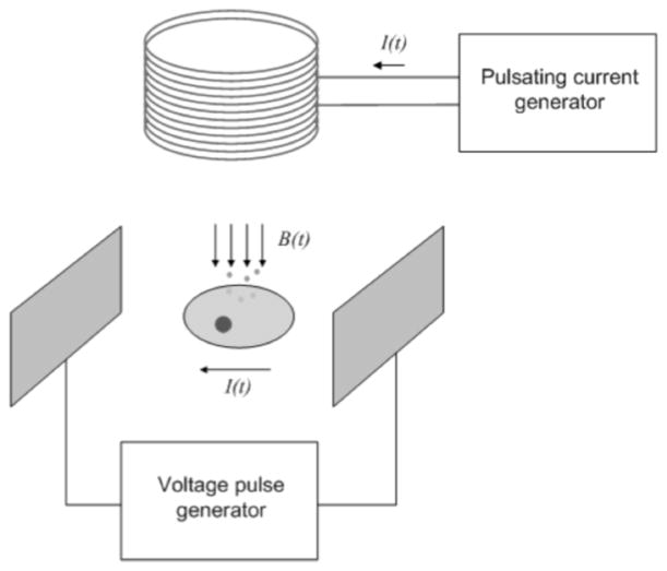
In this work we combine the benefits of electrical and magnetic stimulation in a single device. Fig. (1) depicts the basic setup of the proposed stimulator. It generates time-varying magnetic fields by applying a pulsating current through a coil. The stimulator also generates an electric field across two electrodes by creating a potential difference of +/−40 V between them and it is able to source up to 200 mA when these electrodes are submerged in a culture media. The stimulator is primarily intended for in-vitro dual stimulation of cultured cells, although it can also be used in in-vivo stimulation studies as well. Previous studies suggest that muscle cells respond better to electrical stimulation while bone cells respond better to magnetic stimulation. Thus, the dual stimulator will provide scientists with a tool to study in more detail the pathophysiological crosstalk between bone and muscle and possibly exploiting it for more efficient therapy practices.
Fig. 1.
Dual electrical and magnetic cell stimulation.
STIMULATOR DESIGN
Overall Design
A review of the literature on pulsed magnetic stimulation shows that a wide range of magnetic field intensities have been employed for bone healing ranging from 0.034 μT to 15 mT [13, 14]. The current levels that are needed to generate such magnetic fields intensities can be calculated from Ampere’s Law. Considering a coil of N turns and radius R, the magnetic field B at a distance r from the center of the coil is given by:
| (1) |
where μ0 is the permeability of free space and is equal to 4π×10−7 H/m and I is the current through the coil. To obtain a magnetic field of 15 mT at a distance of 1 cm with a coil of 3cm of radius and 100 turns, a current of 8.4 A is needed. Considering a DC coil resistance of 0.2 Ω, a voltage of 1.7 V will be needed to produce a current of 8.4 A through the coil. Hence, the magnetic stimulation requires a voltage source of relatively low output voltage but with high current drive. These two requirements can be achieved with a high-efficiency and high-current buck converter.
On the other hand, the requirements of the electrical stimulation circuit are: high output voltages (between +/−40 V to +/−60 V) and relatively low output currents (0 to 200 mA). To meet these requirements, a boost converter is employed. Oftentimes, to avoid the buildup of charges in one electrode, electrical stimulation requires bi-phasic pulses. In the proposed stimulator bi-phasic pulses are produced with the help of an H-bridge, thus, avoiding the need of dual voltage polarity circuits.
Hardware Design
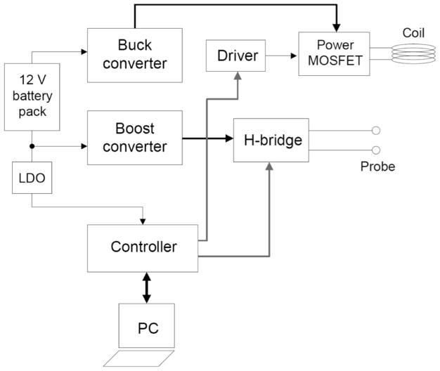
Fig. (2) shows a block diagram of the dual-mode stimulator. The main components of the stimulator are a controller, a buck converter, a boost converter and an output stage composed by an H-bridge and a power MOSFET. The H-bridge is connected to a probe for electrical stimulation and the power MOSFET is connected to a coil to generate a pulsating magnetic field. The buck and the boost converters translate the voltage from the battery pack to voltages levels that are suitable to for the generation of the targeted magnetic and electric fields. The controller provides an interface with the user through a personal computer and generates the control signals that drive the output stage of the stimulator. The controller also monitors the current through the H-bridge to detect short circuit conditions. If an excessively large current (>200 mA) is detected, the controller shuts off the H-bridge. The controller also drives an LCD display for immediate feedback of current through the bridge and the battery voltage. Low-dropout regulators (LDOs) are also included to down-convert the 12 V battery voltage to 3.3 V and 5 V respectively to power up the controller and other ICs in the prototype.
Fig. 2.
Block diagram of the dual-mode cell stimulator.
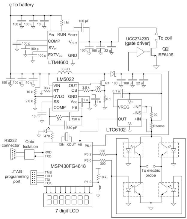
Fig. (3) shows a detailed circuit schematic of the stimulator. The controller is implemented with the low-power MSP430FG4618 microcontroller. A buck converter with a maximum current output of 10 A was built around the LTM4600. The LTM4600 is a high efficiency, high density switch-mode step-down power module [27]. Its input voltage ranges from 4.5 V to 20 V and has a programmable output voltage from 0.6 V to 5 V. It also integrates input and output filters, only bulk input and output capacitors are needed yielding a simple PCB layout. The boost converter was implemented with the integrated circuit LM5022. The LM5022 is a high voltage low-side N-channel MOSFET regulator [28]. Output voltage regulation is based on current-mode control, which eases the design of loop compensation while providing inherent input voltage feed-forward. It includes a start-up regulator that operates over a wide input range of 6V to 60V and a PWM controller designed for high speed capability including an oscillator frequency range up to 2 MHz. Additional features include an error amplifier, precision reference, line under-voltage lockout, slope compensation and thermal shutdown.
Fig. 3.
Detailed schematic diagram of the stimulator.
The current-sense amplifier LTC6102 is employed to monitor the current through the H-bridge. The LTC6102 monitors current via the sense resistor Rsense of 0.05 Ω. The small voltage developed across the sense resistor is converted by the LTC6102 to an output current at pin OUT that flows through ROUT (10 kΩ) creating an output voltage proportional to the current through the bridge. This set up allows a small sense signal on a large common mode voltage to be translated to a ground-referred signal. The output voltage from the current-sense amplifier is read by the microcontroller’s internal ADC. The battery voltage is also monitored via a resistive voltage divider whose output voltage is fed to an input channel of the microcontroller’s internal ADC.
The H-bridge is formed by four opto-isolated bipolar transistors (OPIA 600). The bridge is controlled by two I/O pins from the microcontroller (P6.2 and P6.0). If a bi-phasic stimulation is selected by the user, the transistors Q1-Q3 and Q2-Q4 are turned on in an alternated manner to produce positive and negative flowing currents through the probe. If mono-phasic stimulation is selected, only the Q1-Q3 branch is activated. The power MOSFET is a high-current high-voltage switch (IRF640S) that is controlled by the microcontroller through a gate driver circuit (UCC27423). The stimulator circuit also includes a JTAG programming port for firmware updates, an LED power-on indicator, a reset switch and a RS-232 serial port for communications with a computer.
Firmware Design
The user interacts with the stimulator through menus generated by the microcontroller. The menus and the user inputs are transmitted through the serial port and displayed on a terminal emulation program on the PC. Thus, no special program needs to be installed on the computer. Besides handling the serial communications and the current and battery voltage monitoring, the microcontroller’s main function is to generate a train of pulses with the timing requested by the user. The pulse parameters that can be set by the user are: pulse repetition, pulse duration, time between pulses and rest period. These parameters can be applied independently to both the electric and magnetic stimulation.
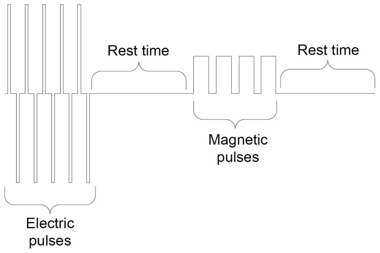
Fig. (4) illustrates the pulse timing. A sequence of electric pulses is generated first by energizing the corresponding transistors of the H-bridge (Q1-Q3 or Q2-Q4). These pulses are followed by a rest period. After the rest period, the coil is energized to generate the magnetic pulses. The widths of the magnetic pulses are modulated from 0% to 100% to offer an additional level of control over the average intensity of the generated magnetic field. The magnetic pulses are followed by a second rest period and the entire sequence is repeated again.
Fig. 4.
Intracellular Timing of output waveforms.
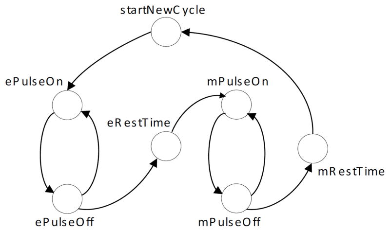
To ensure accurate pulse timing, the microcontroller relies on its internal timer. This timer uses a very stable clock signal generated from a 32 kHz crystal. The pulse sequence is generated by the state machine shown in Fig. (5). At each state the timer is reprogrammed with a new period. When the timer expires, an interruption is triggered and the state machine advances to the next state. The combined usage of the timer and the interruption results in a reliable pulse generation and allows the microcontroller to perform other tasks simultaneously such as serial communications and current and voltage monitoring. The firmware was written in C and has an interrupt-driven architecture.
Fig. 5.
State machine diagram.
RESULTS
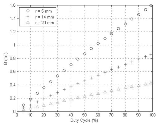
The electric and magnetic outputs of the EM-Stim were characterized individually. The strength of the magnetic field was measured using a gaussmeter (Model 421 Gaussmeter, Lake Shore Cryotronics, Inc., Westerville, OH) at different distances from the center of the coil and at different excitation voltages. Fig. (6) shows the intensity of the measured magnetic field. The intensity was varied by changing the duty cycle of the pulse-width modulated signal that drives the power MOSFET. This method results in a linear relationship between the field intensity and the duty cycle. The duty cycle can be setup by the user through the serial interface. The coil was built using enameled copper wire #30 AWG. The coil has 100 turns and was placed at 5 mm, 14 mm and 20 mm from the gaussmeter probe. The maximum magnetic field is 1.6mT for an excitation voltage of 1.8 V (output voltage of the LTM4600 buck converter). Higher magnetic fields can be obtained by setting higher excitation voltages but that leads to higher currents through the coil which results in heating of the coil. At an excitation voltage of 1.8 V the DC current through the coil is around 0.65 A. The heating problem can be alleviated by using a thicker coil wire or by cooling the coil [29].
Fig. 6. Intensity of the magnetic field produced by the stimulator.
The intensity varies linearly with the duty cycle and is inversely proportional to the distance from the coil.
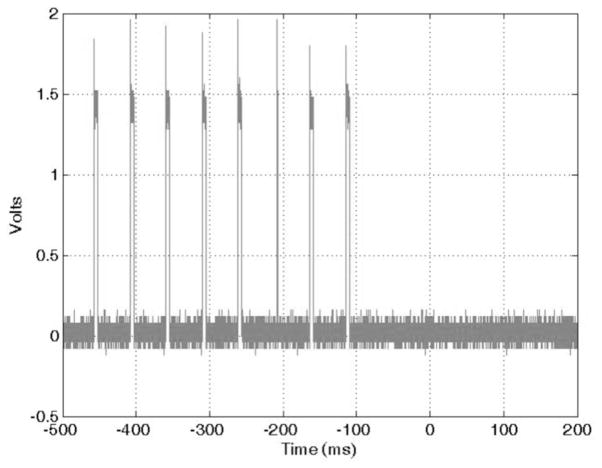
The electric stimulation output was tested by submerging two carbon electrodes in a cell culture media. The multiwell C-Dish (IonOptix, Milton, MA) culture dish assembly was employed for this setup. The C-Dish provides six wells where different cell cultures can be placed and stimulated. The C-Dish electrodes are made of pure carbon to reduce build-up of toxic waste products. An amount of 10 ml of culture media was placed on each well and the EM-Stim was set to generate a train of 10 pulses on its electric stimulation output. Each pulse had duration of 5 ms and a repetition period of 50 ms. The output of the current sense amplifier (LTC6102) was monitored with an oscilloscope (Tektronix MSO 3032). Fig. (7) shows the voltage output of the current sense amplifier. From this voltage waveform, the peak current through the culture media can be calculated. The voltage output of the LTC6102 current sense amplifier is given by:
| (2) |
where Vsense = Isense × Rsense. Thus,
Fig. 7.
Voltage at the output of the current sense amplifier.
| (3) |
Replacing the values of Rsense = 0.05 Ω, Rout = 10 kΩ and Rin = 47 Ω, we obtain a peak current of 140 mA.
Biological Testing and Validation of the EM-Stim
A myogenic cell line of C2C12 cells is being used to test the effects of the electric and magnetic pulses. Variables such as pulse repetition, field strength and rest period duration have been evaluated. Our laboratory has vast expertise with culture of this cell line and primary muscle cells for functional, biochemical, and cell-molecular biological approaches. C2C12 myoblasts were seeded in 6-well plates at a density of 1×10⁵ cells/per well, cultured for 48–72h in Dulbecco’s Modified Eagle Medium (DMEM) media containing 10% fetal bovine serum (FBS) (Growth Medium, GM) until reaching 60% confluence. To induce differentiation, FBS was replaced with 2% horse serum (Differentiation Medium, DIFF). Under these conditions myotubes start to develop within 48–72 h and are fully matured within 120–168 h (5–7 days). To test the effects of our new EM-Stim device, we employed 4 experimental groups: a) naïve control, b) electrical stimulation (ES), c) electromagnetic stimulation (EM), and d) ES + EM. In a series of pilot studies we detected significant cell death when ES was comprised of either long duration pulses that were longer than 20 ms or stimulatory trains longer than 200 ms. To prevent cell death, the following parameters were used in all experiments shown here: 15 V, 20 Hz, stimulatory train of 50 ms, individual pulses of 1 ms, periodicity of 10 min. Under our experimental conditions we have not observed electromagnetic induced cell death with magnetic fields of up to 1.6 mT. For all results presented here EM was set at 1.0 mT also with a periodicity of 10 min. When cells were exposed with both ES and EM, EM stimulation occurred 5 min after ES. Under all conditions stimulation paradigms were maintained for 12 h. In addition, we routinely perform MTT assays for determination of toxicity and under the conditions presented here we did not observe any toxic effects of ES or EM alone and/or both combined. We did observe toxic effects to the cells when either very long electrical pulses or long stimulatory trains were used, likely due to membrane cell damage leading to cell death.
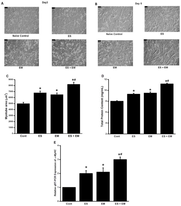
In Fig. (8), the adaptive responses of C2C12 cells to ES, EM, and ES + EM are summarized. Sixty hours after differentiation was induced with DIFF, C2C12 myoblasts were exposed for 12 h to one of each of our 4 experimental conditions, and this process was repeated again at 96 h for another 12 h, and cells allowed differentiating until a total time of 120 h (5 days). These experiments were performed in duplicates and repeated 6 times. Fig. (8A) shows representative phase contrast images of myoblasts in DIFF under each experimental condition at 72 h, thus, after the first bout of 12 h of ES or EM or ES + EM. Fig. (8B) shows representative phase contrast images of myoblasts in DIFF under each experimental condition at 120h, thus, after the second bout of 12 h of ES or EM or ES + EM. Fig. (8C) shows summarized statistical data for myotube cell area at the 120 h time point. For cell area determination, C2C12 myotubes were imaged using a Leica DM 4000B (Leica Microsystems Inc., Buffalo Grove, IL) microscope. Cell areas of individual cells were determined using the Leica Application Suite Advanced Imaging and Fluorescence software package (Leica Microsystems Inc., Buffalo Grove, IL) by defining cells as regions of interest, and then areas were automatically calculated in micrometers squared (μm2) by the Leica software. Both ES and EM significantly increased cell area and synergistic effects were detected when ES + EM were used concomitantly, since the increase in cell area with ES + EM was significantly higher than the individual effects of ES or EM. Immediately after morphological data was gathered for each experiment, one of the duplicate samples was processed for RNA extraction and the other for protein extraction following our own protocols [30–35]. Total RNA was extracted from the myotubes using a standard trizol-based extraction method (Sigma Aldrich, St. Louis, MO), quantified in a Nanodrop spectrophotometer (Thermo Scientific, Wilmington, DE) by determining absorbance at 260 nm in triplicates. Our RNA purity was very high as indicated by the A260/280 nm absorbance ratio of 1.92–2.08. Using 1 μg/μl of RNA, each sample was reverse transcribed in a 20 μl reaction volume with a commercial Quantitec Reverse Transcription Reagents kit (Qiagen Inc, Valencia, CA) according to the manufacturer’s instructions. The expression of α-MHC and GAPDH (reference gene) was investigated using a customized Mouse RT2 Profiler™ PCR Array system (SABio-sciences, Qiagen, Inc., Valencia, CA). qPCR was performed using the Step-OnePl™ Real-Time PCR System (ABI, Foster City, CA, USA) via standard fluorescent methodology and thermal cycling conditions following the manufacture’s recommendations, including a threshold of 0.2 and validation of each gene tested by the identification of single peaks in melting curves. The real-time PCR reaction mixture contained 1 μl of 50 ng of cDNA, 12.5 μl of the RT2 Real-Time TM SYBR Green/Rox PCR master mix, 1 μl of primer pairs and 10.5 μl of RNase free water to a complete reaction of 25 μl. Data was analyzed using RT2 Profiler™ PCR Array software, and relative amounts were calculated by the 2−ΔΔCT method [22]. The CT value of α-MHC was normalized to GAPDH because we also investigated the expression levels and variability for five candidate reference genes (B2m, GAPDH, Hprt1, Rplp1 and Actb), both control and experimental conditions. CT values from GAPDH showed an average of 0.28 cycle difference and an efficiency of 95%; therefore, this gene was selected for normalization purposes.
Fig. 8. EM-Stim promotes C2C12 proliferation and myogenic differentiation.
A) Representative phase contrast images of C2C12 myoblasts cultured 72 h in DIFF that were exposed for 12 h (60–72 h) to control, ES, EM, and ES + EM conditions. B) Essentially the same data shown in panel A, but at 120h. Here cells were stimulated from 96 h to 108 h. C) Summarized cell area data for the myotubes at 120 h, after the 2 bouts of stimulation protocols. D) Total protein content of myotubes at 120h, after the 2 bouts of stimulation protocols. E) α-MHC qRT-PCR summary data for all 4 experimental conditions. In summary while both ES and EM had similar enhancing effects on myogenic differentiation, combination of ES + EM produced synergistic effects in enhancing myogenic differentiation. The black bars on each figure are a calibration bar representing 100μm.
To properly determine total protein concentration myo-tubes were washed three times with PBS and lysed with RIPA Cell extraction buffer (Sigma Aldrich, St. Louis, MO) supplemented with a cocktail of protease and phosphatase inhibitors (Sigma Aldrich, St. Louis, MO). The protein concentrations were quantified using the Micro BCA Protein assay Kit (Pierce, Thermo Fisher Scientific, Rockford, IL) with BSA as standards and quantified by optical density at 562 nm using a Bio-TEK micro-plate reader.
Therefore, to confirm the information gathered from our morphological studies, we measured total protein content as detailed above (Fig. 8D) and quantitative real time gene expression as aforementioned (qRT-PCR; Fig. 8E) of alpha-myosin heavy chain (α-MCH or MyHC6) to confirm both at the protein and gene expression levels the molecular effects of ES, EM, and ES + EM. The results summarized in (Figs. 8D–E) indicate that myogenic differentiation is accelerated by both ES and EM with again the confirmation at the molecular level that ES and EM produce synergistic effects. Our goals now are to extend the stimulation time of C2C12 muscle cells, repeat these experiments in primary muscle cells from animals and humans and perform similar experiments in in-vivo models.
CURRENT AND FUTURE DEVELOPMENTS
A dual-mode electric and magnetic biological stimulator has been presented. The motivation of using dual-mode stimulation comes from the observation that some cells such as muscle cells respond better to electric stimulation and some other cells such as bone cells respond better to magnetic stimulation. Thus, by employing both modalities it is possible to target both types of cells. Furthermore, our results suggest that the combination of ES + EM has synergistic effects in promoting myogenic differentiation of C2C12 myoblasts. Moreover, dual stimulation will allow scientists to study the complex interplay between muscle and bone cells in a controlled environment as well as studying the potentially complex interactions of these different forms of energy. Having a single device that is able to generate both types of stimulation simplifies the setup of experiments and occupies less space on the bench. However, dual-stimulation has potential benefits beyond experimental cell biology studies as it can provide alternative therapy options for degenerative diseases such as sarcopenia and osteoporosis. In this paper we have reported the design and characterization of a dual-mode stimulator dubbed EM-Stim. This stimulator employs commercial-off-the-shelf highly-efficient electronic integrated circuits to generate time-varying magnetic and electric fields. The stimulator is powered up by a 12 V battery or power supply. The supply voltage is transformed by high-efficiency buck and boost converters to generate voltages that feed the output stages of the stimulator. The output stages are controlled by a microcontroller that generates precise timing signals according to the parameters set by the user. The user interacts with the stimulator using a simple terminal emulator program and a serial RS-232 port. A future addition to this stimulator would be to incorporate thermal stimulation to test the effects of hyperthermia in addition to electrical and electromagnetic stimulations.
Acknowledgments
This work was supported with grants from the UMKC Center of Excellence for the Study of Mineralized Tissue, the Missouri Life Sciences Research Board, and a National Institutes of Health-NIH Grand Opportunities (GO) NIAMS 1RC2AR058962-01 to MB, and an NIH P01 National Institutes of Aging grant AG039355-01A1 to LFB and MB.
Footnotes
CONFLICT OF INTEREST
Authors Leon-Salas, Hatem Rizk, Chenglin Mo, and Marco Brotto are also authors of a provisional patent secured by the UMKC Technology Transfer Office with the United States Patent and Trademark Office under application #61/743,500 with a filling receipt of 10/02/2012.
PATIENT CONSENT
Not applicable since no studies were conducted in humans.
Send Orders of Reprints at reprints@benthamscience.net
References
- 1.Wu HC, Young ST, Kuo TS. A versatile multichannel direct-synthesized electrical stimulator for FES applications. IEEE Transactions on Instrumentation and Measurement. 2002;51:2–9. [Google Scholar]
- 2.Poletto CJ, Van Doren CL. A high voltage, constant current stimulator for electrocutaneous stimulation through small electrodes. IEEE Transactions on Biomedical Engineering. 1999;46:929–936. doi: 10.1109/10.775402. [DOI] [PubMed] [Google Scholar]
- 3.Genovese JA, Spadaccio C, Garcia-Rivello H, Todyoda Y, Pate AN. Electrostimulated bone marrow human mesenchymal stem cells produce follistatin. Cytotherapy. 2009;11:448–456. doi: 10.1080/14653240902960445. [DOI] [PubMed] [Google Scholar]
- 4.Weber RJ. Functional neuromuscular stimulation. In: Practice JA DeLisa., editor. Rehabilitation Medicine: Principles. Lippincott; Philadelphia, PA: 1993. [Google Scholar]
- 5.Reilly JP. Applied Bioelectricity: From Electrical Simulations to Electropathology. New York: Springer-Verlag; 1998. [Google Scholar]
- 6.Fujita H, Nedachi T, Kanzaki M. Accelerated de novo sarcomere assembly by electric pulse stimulation in C2C12 myotubes. Experimental cell research. 2007;313:1853–1865. doi: 10.1016/j.yexcr.2007.03.002. [DOI] [PubMed] [Google Scholar]
- 7.IonOptix. Cell culture pacing. 2010 [cited 12/07/2010]; Available from: http://www.ionoptix.com/products/chronic_pacing_systems.
- 8.LGMedSupply. Electronic muscle stimulators. 2010 [cited 12/07/2010]; Available from: http://www.lgmedsupply.com/mustun.html.
- 9.Brandel. Electrical stimulators. 2010 [cited 12/07/2010]; Available from: http://www.brandel.com/estimulator.html.
- 10.Ilic M, Vasiljevic D, Popovic DB. A programmable electronic stimulator for FES systems. IEEE Transactions on Rehabilitation Engineering. 1994;2:234–239. [Google Scholar]
- 11.Jahns M, Durdle N, Lou E, Raso VJ. A programmable ramp waveform generator for PEMF exposure studies on chondrocytes. 28th Annual International Conference of the IEEE Engineering in Medicine and Biology Society: EMBS ‘06; 2006. [DOI] [PubMed] [Google Scholar]
- 12.McNulty MJ, Fogarty P. Design of a highly efficient circuit for electrical muscle stimulation. IEEE Biomedical Circuits and Systems Conference: BioCAS 2006; 2006; 2006. [Google Scholar]
- 13.Markov MS. Magnetic Field Therapy: A Review. Electromagnetic Biology and Medicine. 2007;26:1–23. doi: 10.1080/15368370600925342. [DOI] [PubMed] [Google Scholar]
- 14.Shupak NM. Therapeutic uses of pulsed magnetic-field exposure: a review. Radio Science Bulletin. 2003;307:9–32. [Google Scholar]
- 15.Thomas AW, Drost DJ, Prato FS. Human subjects exposed to a specific pulsed (200 uT) magnetic fields: effects on normal standing balance. Neuroscience Letters. 2001;297:121–124. doi: 10.1016/s0304-3940(00)01688-8. [DOI] [PubMed] [Google Scholar]
- 16.Bassett CAL. Beneficial effects of electromagnetic fields. Journal of Cellular Biochemistry. 1993;51:387–393. doi: 10.1002/jcb.2400510402. [DOI] [PubMed] [Google Scholar]
- 17.MagVenture. Transcranial magnetic stimulation. 2010 [cited 12/07/2010]; Available from: http://www.magventure.com/
- 18.NeuroStar. Transcranial magnetic stimulation (TMS) 2010 [cited 12/07/2010]; Available from: http://www.neurostartms.com/Home.aspx.
- 19.Schneider MB, Mishelevich DJ. Transcranial magnet stimulation of deep brain targets. 8267850. US. 2012
- 20.Orthofix. Cervical-stim is a non-invasive, bone growth stimulator for spine surgery. 2010 [cited 12/07/2010]; Available from: http://www.orthofix.com/products/spine_cervstim.asp?cid=37.
- 21.Cheng KWE, Yan L, Kai-Yu T, Rad AB, Chow DHK, Sutanto D. Development of a circuit for functional electrical stimulation. IEEE Transactions on Neural Systems and Rehabilitation Engineering. 2004;12:43–47. doi: 10.1109/TNSRE.2003.819936. [DOI] [PubMed] [Google Scholar]
- 22.Cheever EA, Thompson DR, Cmolik BL, Santamore WP, George DT. A versatile microprocessor-based multichannel stimulator for skeletal muscle cardiac assist. IEEE Transactions on Biomedical Engineering. 1998;45:56–67. doi: 10.1109/10.650352. [DOI] [PubMed] [Google Scholar]
- 23.Ruohonen J, Ravazzani P, Grandori F. Functional magnetic stimulation: theory and coil optimization. Bioelectrochemistry and Bioenergetics. 1998;47:213–219. [Google Scholar]
- 24.Polk C. Dosimetry of extremely low frequency magnetic fields. Bioelectromagnetics Supplement. 1992;1:209–235. doi: 10.1002/bem.2250130720. [DOI] [PubMed] [Google Scholar]
- 25.Prato FS, Carson JJL, Ossenkopp KP, Kavaliers M. Possible mechanisms by which extremely low frequency magnetic fields affect opioid function. The Federation of American Societies for Experimental Biology Journal. 1995;9:807–814. doi: 10.1096/fasebj.9.9.7601344. [DOI] [PubMed] [Google Scholar]
- 26.Luben RA. Effects of low-energy electromagnetic fields (pulsed and DC) on membrane signal transduction processes in biological systems. Health Physics. 1991;61:15–28. doi: 10.1097/00004032-199107000-00002. [DOI] [PubMed] [Google Scholar]
- 27.Linear. LTM4600-10A high efficiency DC/DC micro-module. 2010 [cited 12/07/2010]; Available from: http://www.linear.com/pc/productDetail.jsp?navId=H0,C1,C1003,C1424,P14812.
- 28.National. LM5022 -60V low side controller for boost and SEPIC. 2010 [cited 12/07/2010]; Available from: http://www.national.com/pf/LM/LM5022.html#Overview.
- 29.Bessho K, Yamada S, Kooto M, Masahashi M, Nakano M. Characteristics of a multilayer eddy-current-type ac magnetic coil with a cooling system. Journal of Applied Physics. 1988;64:6020–6022. [Google Scholar]
- 30.Tjondrokoesoemo A, Li N, Lin PH, et al. Type 1 inositol (1,4,5)-trisphosphate receptor activates ryanodine receptor 1 to mediate calcium sparks signaling in adult mammalian skeletal muscle. J Biol Chem. 2012 Dec 5; doi: 10.1074/jbc.M112.425975. [DOI] [PMC free article] [PubMed] [Google Scholar]
- 31.Romero-Suarez S, Mo C, Touchberry C, et al. Hyperthermia: From Diagnostic and Treatments to New Discoveries. Recent Pat Biotechnol. 2012;6 (3):172–183. doi: 10.2174/1872208311206030172. [DOI] [PMC free article] [PubMed] [Google Scholar]
- 32.Mo C, Romero-Suarez S, Bonewald L, Johnson M, Brotto M. Pros-taglandin E2: From Clinical Applications to Its Potential Role in Bone-Muscle Crosstalk and Myogenic Differentiation. Recent Pat Biotechnol. 2012;6 (3):223–229. doi: 10.2174/1872208311206030223. [DOI] [PMC free article] [PubMed] [Google Scholar]
- 33.Tremblay JP, Goudenege S, Huot NB, Lebel C. Myogenic Differentiation Of Stem Cells And And Uses Thereof. 20130004466A1. US. 2013
- 34.Jähn K, Lara-Castillo N, Brotto L, et al. Skeletal muscle secreted factors prevent glucocorticoid-induced osteocyte apoptosis through activation of β-catenin. Eur Cell Mater. 2012 Sep 12;24:197–209. doi: 10.22203/ecm.v024a14. discussion 209–10. [DOI] [PMC free article] [PubMed] [Google Scholar]
- 35.Haldar SM, Jeyaraj D, Anand P, et al. Kruppel-like factor 15 regulates skeletal muscle lipid flux and exercise adaptation. Proc Natl Acad Sci U S A. 2012 Apr 24;109(17):6739–44. doi: 10.1073/pnas.1121060109. Epub 2012 Apr 9. [DOI] [PMC free article] [PubMed] [Google Scholar]


