Abstract
A wide range of devices is used to obtain intracranial electrocorticography recordings in patients with medically refractory epilepsy, including subdural strip and grid electrodes and depth electrodes. Penetrating depth electrodes are required to access some brain regions, and 1 target site that presents a particular technical challenge is the first transverse temporal gyrus, or Heschl gyrus (HG). The HG is located within the supratemporal plane and has an oblique orientation relative to the sagittal and coronal planes. Large and small branches of the middle cerebral artery abut the pial surface of the HG and must be avoided when planning the electrode trajectory.
Auditory cortex is located within the HG, and there are functional connections between this dorsal temporal lobe region and medial sites commonly implicated in the pathophysiology of temporal lobe epilepsy. At some surgical centers, depth electrodes are routinely placed within the supratemporal plane, and the HG, in patients who require intracranial electrocorticography monitoring for presumed temporal lobe epilepsy. Information from these recordings is reported to facilitate the identification of seizure patterns in patients with or without auditory auras.
To date, only one implantation method has been reported to be safe and effective for placing HG electrodes in a large series of patients undergoing epilepsy surgery. This well-established approach involves inserting the electrodes from a lateral trajectory while using stereoscopic stereotactic angiography to avoid vascular injury. In this report, the authors describe an alternative method for implantation. They use frameless stereotaxy and an oblique insertion trajectory that does not require angiography and allows for the simultaneous placement of subdural grid arrays. Results in 19 patients demonstrate the safety and efficacy of the method.
A variety of intracranial electrode types and implantation strategies have been used to identify seizure foci in patients with medically refractory epilepsy. The specific device and implantation technique used are influenced by what brain region is targeted. Grid and strip electrodes are well suited for recording ECoG activity from surface cortical structures, but penetrating depth electrodes are required to access subcortical brain regions.
Depth electrodes have been used for more than 50 years to target sites throughout the brain. Each site requires an implantation strategy that maximizes the accuracy and safety of the procedure. One target site that presents a particular technical challenge is the first transverse temporal gyrus, or the HG. The HG is located within the supratemporal plane and has an oblique orientation relative to the sagittal and coronal planes. Large and small branches of the middle cerebral artery abut the pial surface of the HG and must be avoided when planning the electrode trajectory.
To date, only 1 implantation method has been reported to be safe and effective for placing HG electrodes in epilepsy surgery patients.1–3,8,9,12 This well-established technique involves inserting depth electrodes into the superior temporal gyrus from a lateral approach by using stereoscopic stereotactic angiography to avoid vascular injury.
This direct lateral approach was pioneered by Bancaud and Talairach > 40 years ago as part of an SEEG strategy designed to place large numbers of depth electrode recording contacts in widely distributed brain locations.6
This allows for simultaneously records from anatomical sites within, and at set locations away from, the presumed epileptic focus. By temporally correlating the electrophysiological progression of epileptiform activity at many different brain sites with the patient’s seizure semiology, the results of SEEG monitoring are used to determine whether, and to what extent, resection will be performed.
Published results demonstrate the safety and efficacy of this depth electrode–based method, and some SEEG proponents suggest that this approach may be superior to pial surface recording techniques.2,9 In recent reports of patients with TLE undergoing SEEG evaluation, depth electrodes were placed within the superior temporal gyrus in all cases, including those with foci subsequently localized to mesial structures. Information gathered from the distributed network of recording contacts, including those outside of the seizure focus, enhanced the ability of the clinical team to classify seizure subtypes and formulate the optimal surgical treatment plan.1,8,9
In the present report, we describe a safe and effective alternative method for placing a depth electrode into the cortex of the supratemporal plane, specifically the HG. This approach does not require angiography and is compatible with simultaneous placement of surface grid arrays over the sylvian fissure. The intent is to capitalize on the advantages of both the depth electrode SEEG and pial surface recording strategies. Results are described for 19 patients.
Methods
Prior to surgery, each patient’s case is reviewed at a multidisciplinary epilepsy conference, and a consensus decision is reached regarding the surgical treatment plan. At our center, the majority of patients with TLE have concordant presurgical diagnostic findings consistent with a unilateral mesial temporal lobe focus, and these patients undergo temporal lobe resection without preoperative intracranial ECoG monitoring. Heschl gyrus depth electrode placement is considered if there is evidence of possible lateral neocortical involvement in the patient’s seizure disorder. In that setting, our usual strategy is to place arrays of recording devices to achieve comprehensive coverage of the anterior and middle temporal lobe. Anterior and ventral neocortical sites are accessed with strip electrodes. Mesial regions (for example, the amygdala and hippocampus) are targeted with a combination of depth and strip electrodes. The lateral surface is covered with at least 1 grid array, and recordings from the dorsal temporal lobe surface (supratemporal plane) are obtained by using an HG depth electrode. The anatomy of the HG is such that a multicontact electrode positioned along the long axis of the gyrus provides field potential recordings extending from an anterolateral to a posteromedial portion of the supratemporal plane. In unusual cases of complex auditory auras, or lesions in the dorsal temporal lobe associated with epilepsy, > 1 depth electrode may be inserted in the supratemporal plane, typically posterior to the HG electrode (that is, the planum temporale). Depth electrode implantations are carried out using a frameless stereotactic system (Stealth Navigation, Medtronic).
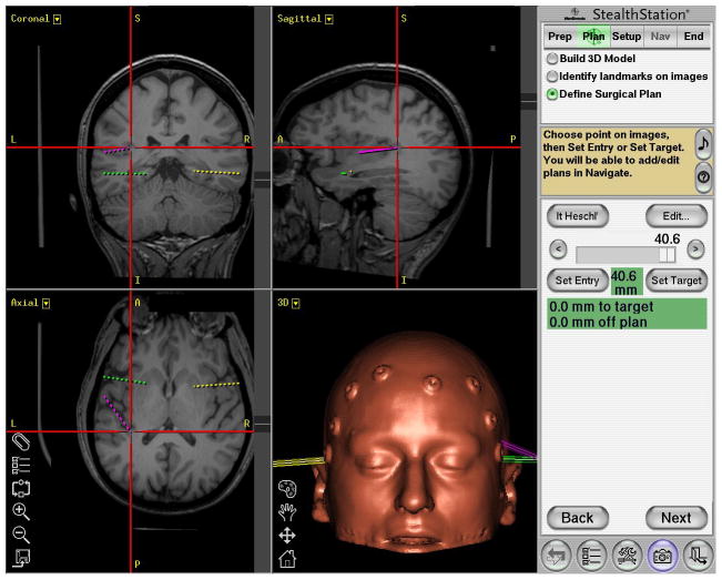
The HG electrode trajectory is determined using the StealthStation. Preoperative thin-slice CT images of the brain taken with 10 surface fiducial points are coregistered and merged with high-resolution MR images. Using the merged images, we select and register an entrance point at the anterior lateral margin of the gyrus, as well as an end point at the posterior medial margin of the gyrus (Fig. 1). The planned electrode trajectory line connecting these 2 points is oriented in such a way that as the electrode enters the HG, it penetrates the gyrus at the level of the gray matter–white matter junction, then shifts slightly upward (dorsal) further into the gray matter of the crest of the gyrus. The tip of the electrode is targeted to end at the level of the HG pial surface. This slight “tilting” of the electrode trajectory is designed to ensure that the recording electrodes are within the gray matter but do not violate the HG pial surface and damage blood vessels in the subarachnoid space. The navigation software calculates an estimated distance from the entry point to the end point, which is typically between 40 and 50 mm.
Fig. 1.
Sample planned of the left HG depth electrode (purple), in addition to left amygdala (green) and right amygdala(yellow), planned using StealthStation. The red cross-hairs center on the left HG trajectory end point, which is typically between 40 and 50 mm from the cortical surface (as seen here at 40.6 mm). The contralateral HG is clearly visible in the axial plane. The orientation of the HG is typically anteroinferolateral to posterosuperomedial. (Note: as with all standard stereotactic planning images, in the coronal and axial plane, the left side of the patient’s anatomy appears on the left side of the image.)
Patients are placed supine. The head is secured in a lateral position with a Mayfield three-pin fixation system. Fiducial points are registered to the stereotactic system with a goal of attaining < 3 mm of estimated error on the StealthStation monitor panel. A large craniotomy is performed to provide access to the hemispheric surface and perisylvian brain regions. Because of the oblique orientation of the HG, it is necessary to expose the temporal lobe to the anterior margin of the sylvian fissure, and the temporalis muscle must be reflected sufficiently to allow positioning of the electrode insertion device.
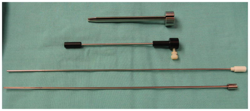
After the craniotomy is performed, a Guide Frame DT StealthStation guide tube (Medtronic Navigation) is positioned over the proposed entrance site and oriented to align the guide tube with the proposed electrode trajectory. The guide tube is then fixed using a flexible fixation device to secure the assembly in the desired position. A custom-made slotted cannula sleeve guide (Ad-Tech Medical Instrument Co.) is inserted into the Guide Frame DT guide tube (Fig. 2). The pial surface overlying the entrance site is coagulated and opened sharply. The estimated distance from the HG entry point to end point is marked on the stylet. A 2.11-mm-diameter, 2-piece slotted cannula (Ad-Tech Medical Instrument Co.), with a blunt-tipped stylet in place, is slowly advanced through the cannula sleeve guide, into the brain and along the electrode trajectory. When the tip of the cannula has reached the estimated depth, the blunt stylet is removed while the cannula is held in place manually. A multicontact depth electrode (Ad-Tech Medical Instrument Co.) that contains a thin flexible stylet is then inserted into the cannula until the tip of the electrode reaches the end of the probe. Prior to insertion, the intended depth of electrode insertion is also marked on the electrode shaft. The electrode stylet, slotted cannula, slotted cannula sleeve guide, and Guide Frame DT guide tube are then carefully removed leaving the depth electrode in position. The flexible electrode shaft is secured to the dura with 4-0 Nurolon suture, and the connector lead is tunneled through the scalp via a separate puncture site. Following implantation surgery, MR imaging is performed to identify the locations of intracranial recording contacts, including the HG contacts.
Fig. 2.
Photograph of the intraoperative guide tube assembly devices for depth electrode placement. From top to bottom: the custom-built slotted cannula sleeve guide, StealthStation needle guide, blunt-tipped stylet, and 2-piece slotted cannula.
Results
To determine the safety and accuracy of this implantation method, we analyzed the medical records and postimplantation imaging studies of all patients who underwent HG depth electrode implantation at our institution from May 2005 to March 2009.
During this 4-year period, 19 HG electrodes were targeted (11 left sided, 8 right) in 19 patients (12 women and 7 men; median age 33 years [range 19–56 years]).
Postoperative MR images were available in 17 cases. Of these 17 cases, there was 1 patient in whom intraoperative StealthStation navigation failed and required freehand passage of the electrode. Of the remaining 16 cases, in 94% of these cases (15 of 16), all, or the majority of electrode contacts were positioned within the gyrus. By comparison, the rate of successful electrode placement in the HG in a series of 7 patients who underwent implantation prior to 2005 and in whom a frame-based method was used, was only 57%. In the 1 case of poor placement that involved the frameless approach, the electrode traversed the arachnoid membranes of the sylvian fissure and entered the cortex of the superior bank of the sylvian fissure. This error occurred during the second case in the frameless series and led to our strategy of using a slightly tilted electrode trajectory, as described in Methods. Since that methodological adjustment, there have been no HG electrode penetrations through the arachnoid of the sylvian fissure.
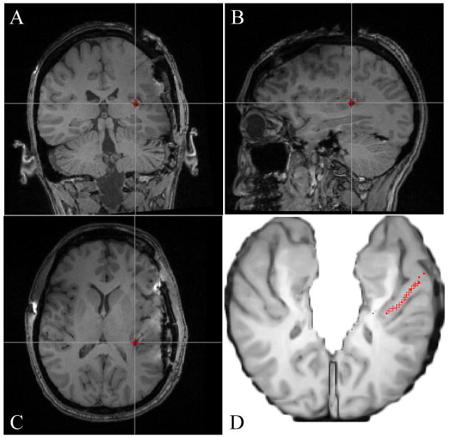
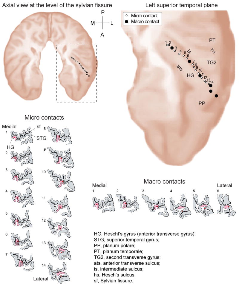
In a representative case, MR images show the electrode artifact, and scaled line drawings demonstrate the locations of electrode contacts along the gyrus (Figs. 3 and 4).
Fig. 3.
A–C: Postimplantation MR images showing a medial HG electrode contact (red cross) in coronal (A), sagittal (B), and axial (C) planes. D: Axial schematic of the supratemporal plane with the HG electrode trajectory marked in red, after coregistration of pre- and postimplantation MR images.
Fig. 4.
Reconstructed trajectory of a left-sided HG depth electrode based on coregistration of pre-and postimplantation MR images, showing the axial projection in the supratemporal plane. Line drawings showing 14 high-impedance microcontacts and 6 low-impedance macrocontacts, from medial to lateral.
On review of the postoperative images, there were no cases of hemorrhage noted along the HG electrode trajectory. On review of the postoperative clinical course, no patients exhibited neurological deficits referable to placement of the HG electrodes. The hybrid nature of the microelectrode and macroelectrode recording allowed detection of multiunit neuronal activity. Detection of multiunit activity on the high impedance microcontacts throughout the recording period suggests viable cortex within ~ 100 μm of the electrode shaft.4,5
Our preliminary observations regarding the clinical usefulness of supratemporal plane recordings are consistent with those reported in larger European series.1–3,8,9 In the 15 patients with accurate MR imaging–confirmed HG placements, electrode-derived data contributed corroborating information that led to a decision not to proceed with resection in 3 patients. In 1 patient, HG electrode data influenced the decision to resect a portion of the superior temporal gyrus. In another patient with auditory auras, seizure onsets were found to involve only mesial temporal lobe structures, and a superior temporal gyrus resection was not performed.
Discussion
The gross anatomy of the human supratemporal plane is complex. This brain region forms the inferior bank of the sylvian fissure and contains obliquely oriented gyri with morphological features that vary significant among individuals and between hemispheres. The most consistently identifiable gyrus is the first transverse temporal gyrus, or the HGs. The auditory cortex is located within HG and the surrounding neocortex of the supratemporal plane. Extensive functional connections exist between these auditory cortical regions and the mesial temporal lobe (for example, the amygdala) in the primate, and auditory auras are sometimes reported in patients with TLE.3,6,8,11,17 Proponents of the SEEG method of intracranial monitoring have contended that depth electrodes placed in the supratemporal plane of patients with TLE provide valuable diagnostic information, irrespective of the presence or absence of auditory auras.1–3,8,9
A number of anatomical factors must be considered when placing electrodes in this brain region. Branches of the middle cerebral artery located within the sylvian fissure are adjacent to the pial surface of the HG, and these vessels must not be injured when implanting a depth electrode. European neurosurgery groups have reported extensive experience with using lateral electrode trajectories, coupled with stereoscopic stereotactic angiography, to place recording contacts in the HG.1–3,6,8,9,12 With this method, the electrode trajectory is oriented obliquely to the long axis of the HG. The electrodes are introduced through small bur holes, advanced through the superior temporal gyrus, and penetrate the lateral boarder of HG at an oblique angle. A relatively short segment of the electrode is positioned within HG, and this segment records from a restricted subregion of the gyrus. In some clinical settings, as many as 4 separate superior temporal gyrus depth electrodes are placed via this lateral approach to achieve the desired coverage of the HG and the supratemporal plane.3,6 Information from the preoperative angiogram enables the surgeon to choose a trajectory that avoids the sylvian fissure and sulcal vessels that are visualized on the imaging study.
The safety of this angiography-based approach has been demonstrated in several clinical series.1–3,6,8,9,12 In a report of 149 patients who underwent epilepsy surgery and in whom depth electrodes were implanted, the HG was targeted in 120 cases (43%). There were no cases of symptomatic hemorrhage or new neurological deficits.12 Numerous studies of human auditory cortex physiology have been conducted using this implantation method, attesting to the functional integrity of these HG electrodes.7
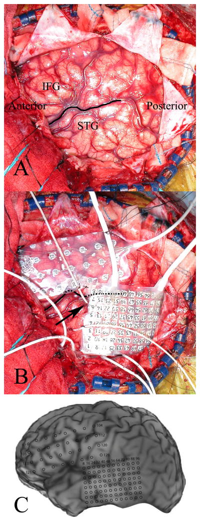
The alternative method described in the current report was developed for several reasons. We wanted to eliminate the need for an angiogram and hypothesized that by introducing the electrode along the full length of this obliquely oriented gyrus, sulcal and sylvian fissure vessels would be avoided. This would also provide better ECoG coverage of the entire gyrus, which has functionally distinct fields located along its length. As with other groups, at our institution we often use both grid and depth electrodes.16 By using an oblique insertion method, the HG entry point is located far enough anteriorly to allow concomitant placement of a lateral surface grid that spans the perisylvian region (Fig. 5). This grid is used to obtain lateral ECoG recordings and for functional mapping, and covers the portion of the superior temporal gyrus that would be used as an entrance point for a lateral electrode trajectory targeting the HG.
Fig. 5.
A: Left hemisphere craniotomy exposing the perisylvian brain regions. The sylvian fissure (dark line), posterior aspect of the inferior frontal gyrus (IFG), and superior temporal gyrus (STG) are all well visualized. B: The HG depth electrode entrance site (arrow) is positioned anteriorly along the superior temporal gyrus, allowing for concomitant placement of a lateral temporal lobe grid. C: The locations of recording contacts are shown on the patient’s 3D surface-rendered MR image.
Our results demonstrate the safety and accuracy of this approach. No clinically significant complications were observed in response to HG electrode placement. As described in previous reports, the frameless stereotaxic system was effective in aligning an electrode guide tube along the desired trajectory, and the flexibility of the positioning system was particularly well suited to this clinical application.10,13–15 All electrodes were confirmed to be within the HG on postoperative imaging studies.
Our preliminary findings regarding the clinical utility of HG recordings in guiding clinical decision-making appear consistent with those reported by investigators who have used the SEEG method.1–3,8,9 However, a larger patient series will be required to reach definitive conclusions regarding the relative utility of this approach compared with monitoring strategies that do not involve accessing the dorsal surface of the temporal lobe.
Conclusions
In this report we describe a safe and accurate method for placing depth electrodes within the HG. This method results in the positioning of electrode contacts along the entire length of the gyrus. It also allows for the combined use of depth and grid electrodes.
Acknowledgments
The authors thank Carol Dizack for artwork. They also thank their patient volunteers for making this generous scientific contribution.
Disclosure
This work was supported by funding from the National Institutes of Health (grant nos. DC-04290 and M01-RR00059).
Abbreviations used in this paper
- ECoG
electrocorticography
- HG
Heschl gyrus
- SEEG
stereoelectroencephalography
- TLE
temporal lobe epilepsy
References
- 1.Bartolomei F, Chauvel P, Wendling F. Epileptogenicity of brain structures in human temporal lobe epilepsy: a quantified study from intracerebral EEG. Brain. 2008;131:1818–1830. doi: 10.1093/brain/awn111. [DOI] [PubMed] [Google Scholar]
- 2.Bartolomei F, Wendling F, Vignal JP, Kochen S, Bellanger JJ, Badier JM, et al. Seizures of temporal lobe epilepsy: identification of subtypes by coherence analysis using stereo-electroencephalography. Clin Neurophysiol. 1999;110:1741–1754. doi: 10.1016/s1388-2457(99)00107-8. [DOI] [PubMed] [Google Scholar]
- 3.Gavaret M, Badier JM, Marquis P, McGonigal A, Bartolomei F, Regis J, et al. Electric source imaging in frontal lobe epilepsy. J Clin Neurophysiol. 2006;23:358–370. doi: 10.1097/01.wnp.0000214588.94843.c2. [DOI] [PubMed] [Google Scholar]
- 4.Howard MA, Volkov IO, Noh MD, Granner MA, Mirsky R, Garell PC. Chronic microelectrode investigations of normal human brain physiology using a hybrid depth electrode. Stereotact Funct Neurosurg. 1997;68:236–242. doi: 10.1159/000099931. [DOI] [PubMed] [Google Scholar]
- 5.Howard MA, III, Volkov IO, Granner MA, Damasio HM, Ollendieck MC, Bakken HE. A hybrid clinical-research depth electrode for acute and chronic in vivo microelectrode recording of human brain neurons. Technical note. J Neurosurg. 1996;84:129–132. doi: 10.3171/jns.1996.84.1.0129. [DOI] [PubMed] [Google Scholar]
- 6.Kahane P, Landre E, Minotti L, Francione S, Ryvlin P. The Bancaud and Talairach view on the epileptogenic zone: a working hypothesis. Epileptic Disord. 2006;8(2 Suppl):S16–S26. [PubMed] [Google Scholar]
- 7.Liegeois-Chauvel C, Musolino A, Badier JM, Marquis P, Chauvel P. Evoked potentials recorded from the auditory cortex in man: evaluation and topography of the middle latency components. Electroencephalogr Clin Neurophysiol. 1994;92:204–214. doi: 10.1016/0168-5597(94)90064-7. [DOI] [PubMed] [Google Scholar]
- 8.Maillard L, Vignal JP, Gavaret M, Guye M, Biraben A, McGonigal A, et al. Semiologic and electrophysiologic correlations in temporal lobe seizure subtypes. Epilepsia. 2004;45:1590–1599. doi: 10.1111/j.0013-9580.2004.09704.x. [DOI] [PubMed] [Google Scholar]
- 9.McGonigal A, Bartolomei F, Regis J, Guye M, Gavaret M, Trebuchon-Da Fonseca A, et al. Stereoelectroencephalography in presurgical assessment of MRI-negative epilepsy. Brain. 2007;130:3169–3183. doi: 10.1093/brain/awm218. [DOI] [PubMed] [Google Scholar]
- 10.Mehta AD, Labar D, Dean A, Harden C, Hosain S, Pak J, et al. Frameless stereotactic placement of depth electrodes in epilepsy surgery. J Neurosurg. 2005;102:1040–1045. doi: 10.3171/jns.2005.102.6.1040. [DOI] [PubMed] [Google Scholar]
- 11.Morris JS, Friston KJ, Dolan RJ. Experience-dependent modulation of tonotopic neural responses in human auditory cortex. Proc Biol Sci. 1998;265:649–657. doi: 10.1098/rspb.1998.0343. [DOI] [PMC free article] [PubMed] [Google Scholar]
- 12.Munari C. Depth electrode implantation at Hôpital Sainte Anne, Paris. In: Engel J Jr, editor. Surgical Treatment of the Epilepsies. New York: Raven Press; 1987. pp. 583–588. [Google Scholar]
- 13.Olivier A, Germano IM, Cukiert A, Peters T. Frameless stereotaxy for surgery of the epilepsies: preliminary experience. Technical note. J Neurosurg. 1994;81:629–633. doi: 10.3171/jns.1994.81.4.0629. [DOI] [PubMed] [Google Scholar]
- 14.Ross DA, Brunberg JA, Drury I, Henry TR. Intracerebral depth electrode monitoring in partial epilepsy: the morbidity and efficacy of placement using magnetic resonance image-guided stereotactic surgery. Neurosurgery. 1996;39:327–334. doi: 10.1097/00006123-199608000-00018. [DOI] [PubMed] [Google Scholar]
- 15.Shenai MB, Ross DA, Sagher O. The use of multiplanar trajectory planning in the stereotactic placement of depth electrodes. Neurosurgery. 2007;60:272–276. doi: 10.1227/01.NEU.0000255390.92785.A4. [DOI] [PubMed] [Google Scholar]
- 16.Spencer SS, So NK, Engel J, Jr, Williamson PD, Levesque MF, Spencer DD. Depth electrodes. In: Engel J Jr, editor. Surgical Treatment of the Epilepsies. 2. New York: Raven Press; 1993. pp. 359–376. [Google Scholar]
- 17.Yukie M. Connections between the amygdala and auditory cortical areas in the macaque monkey. Neurosci Res. 2002;42:219–229. doi: 10.1016/s0168-0102(01)00325-x. [DOI] [PubMed] [Google Scholar]


