Abstract
Background
Neurosurgical procedures involving tumor resection require surgical planning such that the surgical path to the tumor is determined to minimize the impact on healthy tissue and brain function. This work demonstrates a predictive tool to aid neurosurgeons in planning tumor resection therapies by finding an optimal model-selected patient orientation that minimizes lateral brain shift in the field of view. Such orientations may facilitate tumor access and removal, possibly reduce the need for retraction, and could minimize the impact of brain shift on image-guided procedures.
Methods
In this study, preoperative magnetic resonance images were utilized in conjunction with pre- and post-resection laser range scans of the craniotomy and cortical surface to produce patient-specific finite element models of intraoperative shift for 6 cases. These cases were used to calibrate a model (i.e., provide general rules for the application of patient positioning parameters) as well as determine the current model-based framework predictive capabilities. Finally, an objective function is proposed that minimizes shift subject to patient position parameters. Patient positioning parameters were then optimized and compared to our neurosurgeon as a preliminary study.
Results
The proposed model-driven brain shift minimization objective function suggests an overall reduction of brain shift by 23 % over experiential methods.
Conclusions
This work recasts surgical simulation from a trial-and-error process to one where options are presented to the surgeon arising from an optimization of surgical goals. To our knowledge, this is the first realization of an evaluative tool for surgical planning that attempts to optimize surgical approach by means of shift minimization in this manner.
Background
As current standard of care, neurosurgical intervention involving tumor resection is performed with the aid of neuronavigation systems. The basis of these neuronavigation systems consists of the use of a localizer and a computer system to relate position and orientation of a tracked surgical instrument to features of interest in a preoperative tomographic image, enabling what is known as image-guided surgery (IGS). IGS systems improve spatial orientation during the intraoperative planning phase as well as assist in performing resection. The current commercial IGS systems used in neurosurgery make the underlying assumption that the patient’s head and its contents behave as a rigid body. However, studies have shown [1,2] that this assumption is invalid owing to significant positional error in the brain between the time of imaging and the time of the interventional procedure after opening the skull. Often referred to as ‘brain shift’, the nonrigid deformation of the brain occurring upon performing a craniotomy is due to a variety of mechanisms including hyperosmotic drugs, edema, gravity-induced sagging, and surgical manipulation such as from retraction and tissue resection [1,3,4].
Strategies for the compensation of intraoperative brain shift have fallen into two categories—active intraoperative imaging [4–7] and preoperative image updates based upon the estimated displacements derived from biomechanical models [8–13]. With the latter, many approaches have been proposed with variations usually dependent on the data used to constrain the models. For example, the work by Ferrant et al. [10] used intraoperative magnetic resonance imaging data and biomechanical models to achieve volumetric intraoperative transforms, while the work by Chen et al. [14] was solely driven by cortical surface deformation data. Typically, data-driven computer models can compensate for 70–80%of the brain shift on average depending on the study [14]. This degree of compensation for intraoperative brain shift suggests that a biomechanical simulation environment may be considered sufficiently capable of translating complex surgical events into accurate estimates of tissue response. The potential for using such models in a predictive sense for determining the effects of surgical decisions is intriguing.
With an effective preoperative planning tool based on biomechanical modeling, the possibility exists for anticipating and optimizing the surgical orientation to mitigate guidance degradation or to enhance access. In this paper, we hypothesize that it may be possible to parameterize the planning variables to minimize the deleterious effects of shift after the surgeon has selected the approach. In addition, although not presented in this paper, we also hypothesize that computer models combined with surgical parameter optimization can generate ‘favorable’ brain shifts that facilitate visualization and presentation of the tumor for resection. To summarize, the goal of this paper is to present a framework that obtains an ‘optimal’ orientation to minimize shift, and in so doing, a potential tool is created to further investigate surgical therapy planning.
Methods
As indicated above, the methods to be introduced represent an initial optimization framework that provides guidance to surgeon- elected intraoperative presentation variables to achieve best respective outcome. As determining the optimal surgical orientation is currently a subjective assessment, this was provided by our veteran neurosurgeon [RCT]. To qualify, [RCT] is currently Professor and Chairman of the Department of Neurological Surgery, Director of Neurosurgical Oncology, Director of the Vanderbilt Brain Tumor Center. [RCT] has over 20 years of neurosurgical experience and has performed over 3,000 craniotomies—themajority of which are for brain tumors. This work reflects the creation of a predictive tool based upon those experiences and awaits further accrual to confirm those ‘optimal’ surgical orientations. Prior to relaying the optimization framework, the biomechanical model for modeling brain deformation must be calibrated such that it encompasses the widest possible parameter space reflective of intraoperative conditions.
Calibrated computational model
Building upon previous work [9], preoperative images were used to generate computational models for six patients. The preoperative MR images were acquired on Philips Achieva Dual Nova 1.5T using three-dimensional spoiled gradient recalled echo (3D-SPGR) sequences that are typical for neurosurgical image-guidance with 1 mm in-plane resolution and 1.2 mm slice thickness. Image segmentation was achieved using an automatic approach that uses an adaptive basis algorithm [15]. From segmented surfaces, a subject-specific 3D finite element computational model is generated, which has been shown to predict deformations as a result of various patient head orientations during surgery [16]. This model is capable of simulating the effects of hyperosmotic drugs, gravity-induced deformation, retraction, resection, and swelling from edema. The model treats soft tissues as a poroelastic medium according to Biot’s consolidation equations. The equations associated with mechanical equilibrium and continuity are as follows
| (1) |
| (2) |
with the details reported extensively in [9,17,18]. Important to the realization in this paper, kcapp is the capillary permeability and pcapp the intracapillary pressure. The right hand sides of equations (1) and (2) describe terms used to simulate brain sag due to gravitational forces, and the volume-reducing tissue contraction associated with hyperosmotic drugs such as mannitol [9]. The material properties used for clinical cases are listed in Table 1.
Table 1.
Model material properties
| Symbol | Description | Value | Units |
|---|---|---|---|
| G, white and gray | Shear modulus | 724 | N/m2 |
| ν | Poisson’s ratio | 0.45 | Unitless |
| ρt | Tissue density | 1,000 | kg/m3 |
| ρf | CSF density | 1,000 | kg/m3 |
| g | gravity constant | 9.81 | m/s2 |
| α | Saturation constant | 1 | Unitless |
| 1/S | Compressibility constant | 0 | 1/Pa |
| kwhite | Hydraulic conductivity of white matter | 1× 10⁻¹⁰ | m3s/kg |
| kgray | Hydraulic conductivity of gray matter | 5 × 10⁻¹² | m3s/kg |
| kcapp, white and gray | Capillary permeability | Variable | 1/(Pa s) |
| pcapp, mannitol | Intracapillary pressure | −3,633 | Pa |
As part of the process of calibrating a ‘general’ model subject for surgical prediction, it was found that varying capillary permeability kcapp values (associated with swelling and hyperosmotic drugs) produced improved results in model-fitting of the surgical parameters to the laser range scan (LRS) deformation data over a series of clinical cases. To determine a general functional relationship, kcapp calibration curves were fit via manual optimization for six different clinical cases based on the best shift predictions for each case. Table 2 reports the values found in the fitting process. Ageneral model for the best-fit kcapp across cases was found,
| (3) |
where V is the volume of the tumor in cm3, and kcapp has units of Pa−1 s−1. With respect to the fit to data, the squared correlation coefficient value was R2 = 0.88.
Table 2.
The data points for 6 cases used to establish the kcapp versus tumor volume curves
| Case | Tumor volume (cm3) | Tumor radius (m) | k capp, forces |
|---|---|---|---|
| 1 | 63.6103 | 0.024756 | 3.00E-08 |
| 2 | 60.2338 | 0.025640 | 3.75E-08 |
| 3 | 10.7679 | 0.014384 | 7.00E-09 |
| 4 | 22.9275 | 0.017897 | 2.10E-08 |
| 5 | 5.2989 | 0.012820 | 8.00E-09 |
| 6 | 27.6589 | 0.018485 | 1.50E-08 |
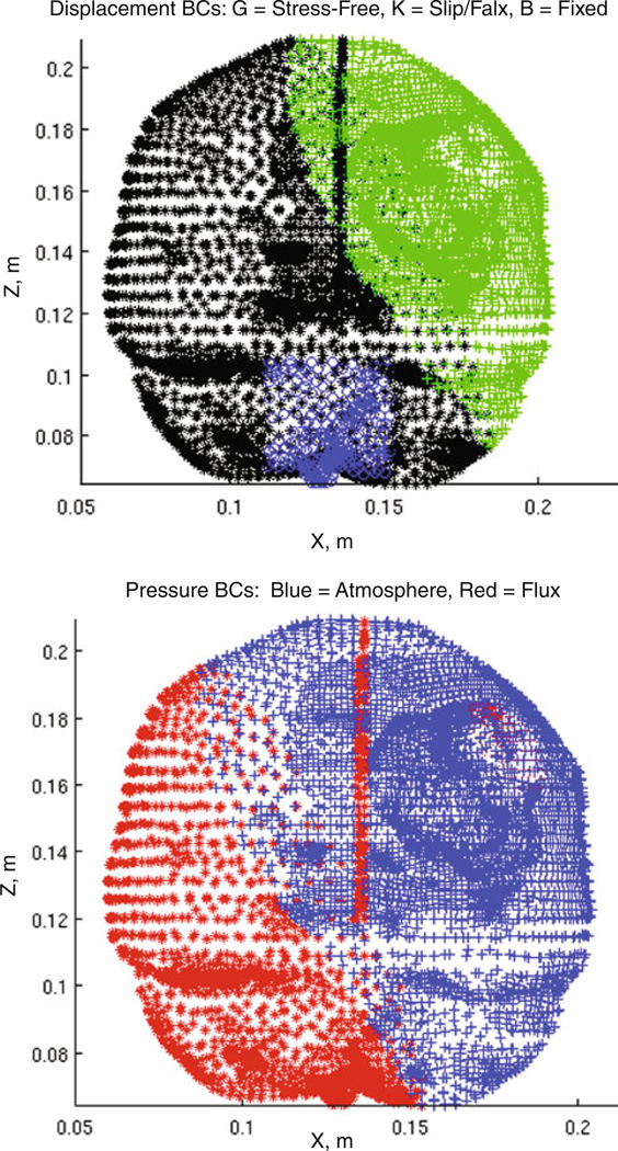
The last aspect to define a predictive computational biomechanical model is to prescribe boundary conditions. In previous work, Dumpuri et al. in [16] developed a framework to automatically deploy boundary conditions as a function of the head orientation. Briefly, once the head was oriented, boundaries at high elevations relative to gravity were free to deform, boundaries at lower elevations were allowed to slide along the cranial wall but not allowed to move normal to the wall (i.e., a slip condition), and boundaries near the brain stem were fixed. With respect to interstitial pressure, boundaries above cerebrospinal fluid drainage levels were open to atmosphere, while boundaries below were prescribed no drainage conditions. An example boundary condition set is shown in Fig. 1 (boundary conditions reflect a head rotation about the cranial-caudal axis with some rotation about the ventral-dorsal axis).
Fig. 1.
Example boundary conditions, Example boundary conditions of an orientation within an atlas set where (top) green crosses are stress-free (free to deform in x-, y-, and z-), black stars are slip nodes (no movement in the normal direction), and blue circles are fixed nodes. (bottom) The CSF drainage level for the example set is shown where red stars indicate submersion of the mesh element and blue crosses indicate atmospheric pressure
Objective function and optimization
With the model prescribed, a general platform for the prediction of brain deformations during tumor resection is provided. With respect to our participating neurosurgeon, (RCT), it was common practice to select head orientations minimizing the impact of brain shift. More specifically, (RCT) would often choose alignments using the falx membrane to provide support and reduce anterior–posterior shift induced by gravity. This shift minimization strategy suggests the establishment of displacement-based metrics of the cortical surface as a primary component within our optimization framework. Two such metrics were found useful: (1) minimization of the lateral shift of the tumor center as viewed along the line of sight established by the surgical ‘approach’ vector to the tumor and (2) an area-based measure consisting of minimization of the change to the field of view in the craniotomy proved relevant. Quantification of the change in the field of view was achieved by the classification of the cortical area within the craniotomy. The cortical area map before intervention was established based on the proposed site of the craniotomy and estimated radius as prescribed by (RCT) in preoperative planning. Using model predictions within the context of our optimization framework, the area in the craniotomy was reassessed to determine regions common before and after deformation.
Based on this, an objective function was created for least squared error minimization of brain shift metrics. These metrics varied with respect to the spherical angles phi and theta (see Appendix for further coordinate system details) associated with changing patient orientation. The objective function combining the metrics is written as
| (4) |
where A is the area of the craniotomy, and Ao is the area that remains visually the same in the field of view such that A–Ao is the area leaving the craniotomy, υ⃗ is the surgical ‘approach’ vector, and δ⃗ = [δx, δy, δz] are the tumor center x-, y-, and z-displacement components. The expression δ⃗ − δ⃗·υ⃗ represents the lateral component of the tumor displacement as viewed along the line of sight of the ‘approach’ vector. Owing to the difference in the measures associated with each brain shift metric, each metric required parameter scaling to prevent one measure from being unduly emphasized in the optimization method. Additionally, the measures could be further weighted for relative importance. Consequently, the scalars λi in Eq. (4) were empirically weighted factors that were scaled with the inverse of variance associated with each factor over a range of solutions. The optimization method used to find the minimum was the secant method (SM). The derivatives for the Jacobian matrix were constructed using backward finite difference approximations. The optimization terminated when the absolute difference between objective function evaluations for successive orientations achieved a tolerance.
Experimental testing
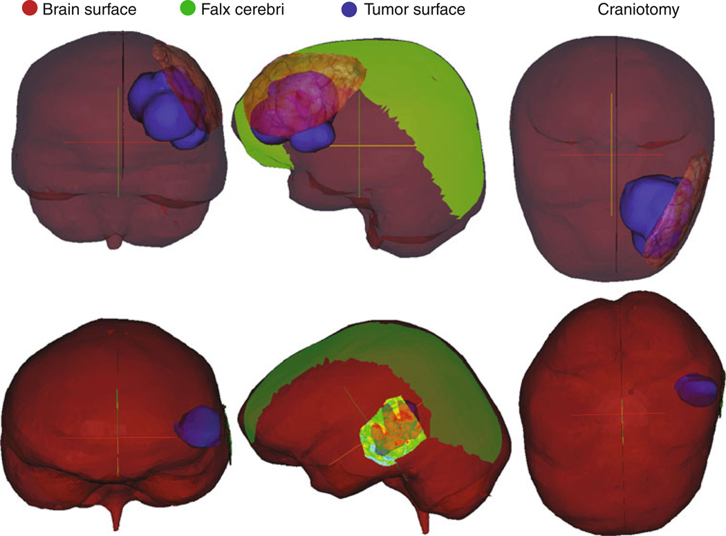
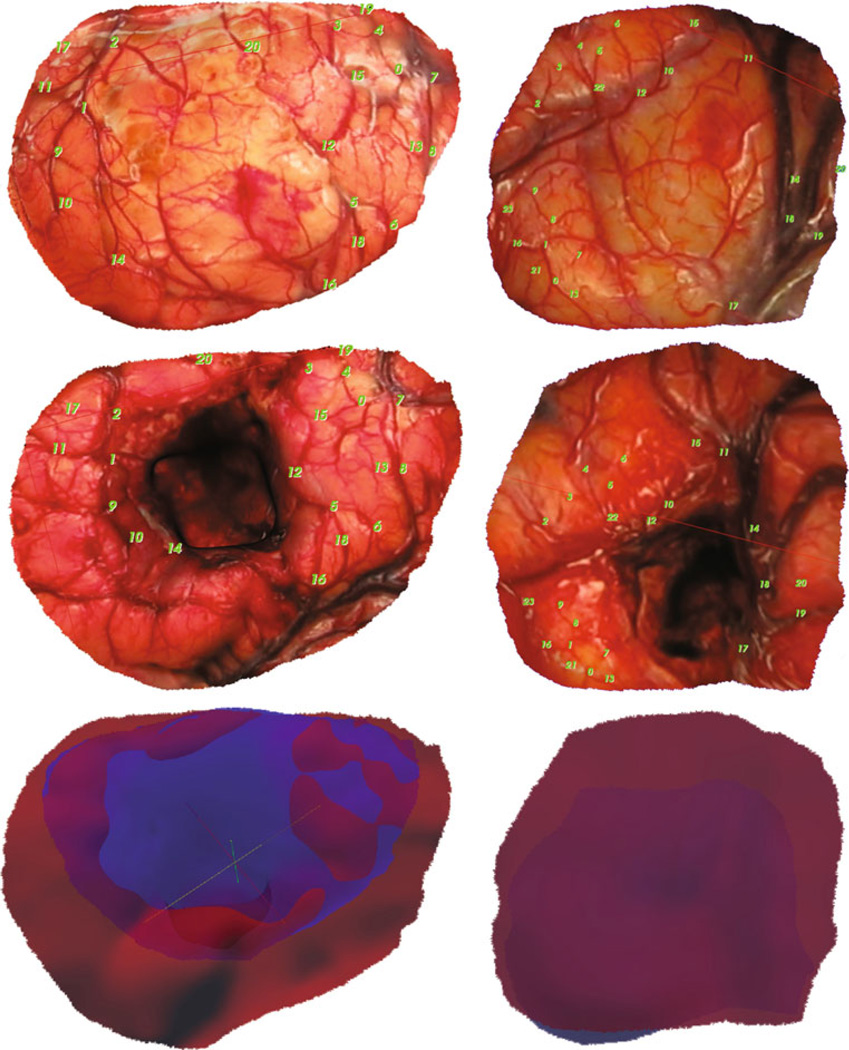
LRS data of the cortical surface before and after deformation were acquired for six clinical cases. All data acquired for patients were done so under an approved protocol by the Vanderbilt University Institutional Review Board (IRB #010520). Prior to any acquisition and analysis, a signed informed consent was obtained from the participant by (RCT). Texture-mapped LRS point clouds taken pre- and post-resection of the operative field and transformed to the same physical space were fit with radial basis function (RBF) surfaces. For each case, these RBF surfaces were segmented to produce cortical surfaces and were used to define the craniotomy area and shape (Fig. 2). As can be seen in Fig. 3, homologous points at vessel intersections identifiable in both the pre- and post-resection cortical surfaces could be selected and used as measurements of brain deformation. These cases were used as a means to generate our ‘generic’ model predictive framework, for example, the generation of Eq. (3) to account for mannitol effects. With each case, an exhaustive search of the model parameter space was done to generate the surgical presentation parameters for the best possible fit of the deformation data as derived from intraoperative LRS. These would represent a best model-fit of surgical parameters as executed by [RCT] in an effort to minimize brain shift based on surgical experience. While direct measurements of some surgical parameters, for example, head orientation, would be better than that determined by a best model-fit, it should be noted that this is very difficult in practice; that is, often during the course of a procedure, elevations and head tilts are changed through manipulations of the surgical bed. In some respect, the parameters derived in this search represent a best average fit over the range of parameters experienced during a case. With respect to analysis, from this fit, the shift of targeted landmarks as predicted by the model could then be compared to the shift of the same landmarks resulting from use of the surgical parameters as determined by the optimization framework. This allows us to compare our optimized surgical parameter set to that used clinically by [RCT], as well as to provide a model estimate to the degree an optimized approach might be better than [RCT]’s clinical results.
Fig. 2.
Patient-specific modeling. Coronal, sagittal, and axial views of case 1 (top) and case 3 (bottom) as examples showing the patient-specific model features where brain surface is red, the tumor surface is blue, falx is green, and the textured preoperative LRS surface indicates the craniotomy placement: (left) coronal (middle) sagittal (right) axial
Fig. 3.
LRS Registration and Area Mapping, (left column) case 1 and (right column) case 6 with (top) examples of homologous control point selection on the preresection LRS, and (middle) the post-resection LRS surfaces that result after thin-plate spline image registration using these control points. Also shown (bottom) are overlays of the deformed pre- LRS surface in blue and the post-surface in red
Objective function optimization proceeded with creating a sampling of patient orientations defining an extent of the parameter space for each metric, that is, an atlas of parameterized deformations. The atlas extent included the orientations by [RCT]. As an initial condition for orientation from which to begin optimization, the default patient position consisted of gravity directed along the anterior–posterior axis with the patient lying supine (head neutral) —a presentation that is often adopted by many practicing neurosurgeons. This supine patient position also served as the neutral position for rotation angles in a spherical coordinate system defined as ϕ = 0° for rotation about the cranial–caudal axis and θ = 0° for tilting the head about the ventral-dorsal axis (see Appendix for coordinate system details). Given Eq. (4), the optimal solution that minimized shift subject to the surgical parameters of the patient-specific model geometry solution distribution was determined.
Results
Calibrated model
The clinical case analysis proceeded with patient-specific models constructed from the six sets of image tomograms and LRS scan data. Figure 2 illustrates frontal lobe (case 1) and temporal lobe (case 3) descriptions of example models. The coronal, sagittal, and axial views detail the brain surface, the extent and shape of the patient-specific falx inserted into the model, the craniotomy used as the field of view, and the tumor. The defined craniotomy encompassed the maximum cortical surface area with surface features clearly visible in the LRS data. Figure 3 shows the homologous points mentioned previously, for example, cases 1 and 6 and the thin-plate spline fitting of the preresection cortical surface to the post-resection cortical surface using those points as controls. The point distribution sought to capture the extent of intraoperative brain shift around the edges of the resection cavity and surrounding tissue. This type of data was collected for all cases and used in the model calibration process. Observing Table 3, columns 9–13 report the best possible fit using our model to the LRS data as procedurally executed by [RCT] over the 6 cases. The average overall cortical displacement of the best model-fit of the surgical parameters for the cases is 11.2 mm, or 93 % of the measured LRS deformation data, and the lateral shift component of the cortical surface landmarks is 5.5 mm, or 86%of the LRS values. While these magnitudes of shift are representative, the accuracy of prediction of the best-fit parameters reflected 74.2 %, which is comparable to studies reported in the literature.
Table 3.
Best surgical and model orientations with LRS deformation data
| Case Number |
Tumor Location |
LRS shift of cortical Surface points (mm) |
Lateral shift LRS cortical Surface points (mm) |
SM Optimized | Model shift of cortical Surface points(mm) |
Lateral shift model cortical Surface points (mm) |
Best surgical | Model shift of cortical Surface points (mm) |
Lateral shift model cortical Surface points(mm) |
|||
|---|---|---|---|---|---|---|---|---|---|---|---|---|
| phi,◦ | theta,◦ | phi,◦ | theta,◦ | % shift prediction |
||||||||
| 1 | LF | 14.3 | 8.0 | 88.1 | 31.9 | 13.2 | 4.8 | 74.2 | −16.5 | 66.9 | 13.2 | 7.8 |
| 2 | LF | 22.2 | 17.9 | 74.2 | 32 | 10.3 | 3.3 | 103.8 | 12.3 | 67.7 | 18.4 | 14.5 |
| 3 | LT | 8.8 | 3.0 | 89.7 | 0 | 9.7 | 1.2 | 74.8 | −22.4 | 87.4 | 9 | 2.8 |
| 4 | LT | 11.8 | 1.6 | 84.9 | −8 | 9 | 0.7 | 75 | −24.4 | 89.8 | 12.1 | 1.6 |
| 5 | RT | 8.6 | 1.8 | −107.1 | −16 | 7.1 | 0.4 | −76.2 | −14.1 | 77.7 | 9.2 | 1.4 |
| 6 | LTP | 6.9 | 5.8 | 90.7 | 18.3 | 6.5 | 1.1 | 96.1 | −4.8 | 55.5 | 5.5 | 4.8 |
| Average | 12.1 | 6.4 | 9.3 | 1.9 | 74.2 | 11.2 | 5.5 | |||||
Optimization characterization and performance
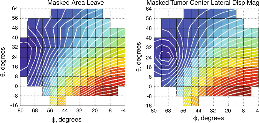
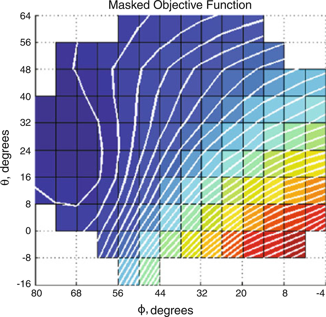
Post-processing of the atlas displacement solutions produced the fitted parameter space for finding optimal orientation per metric (Fig. 4, case 2 shown). Objective function evaluations for the atlas orientations similarly formed a parameter space (Fig. 5) whose minimum could be found by the secant method.
Fig. 4.
Atlas results for shift metrics. Brain shift metric surfaces derived from masked orientation atlases for case 2 (left) indicating area leaving (m2) and (right) representing tumor center lateral displacement magnitude (m)
Fig. 5.
Atlas-derived objective function. Masked objective function for case 2. (left) is objective function consisting of area and tumor center lateral shift measures equally weighted. Darker areas are smaller objective function values
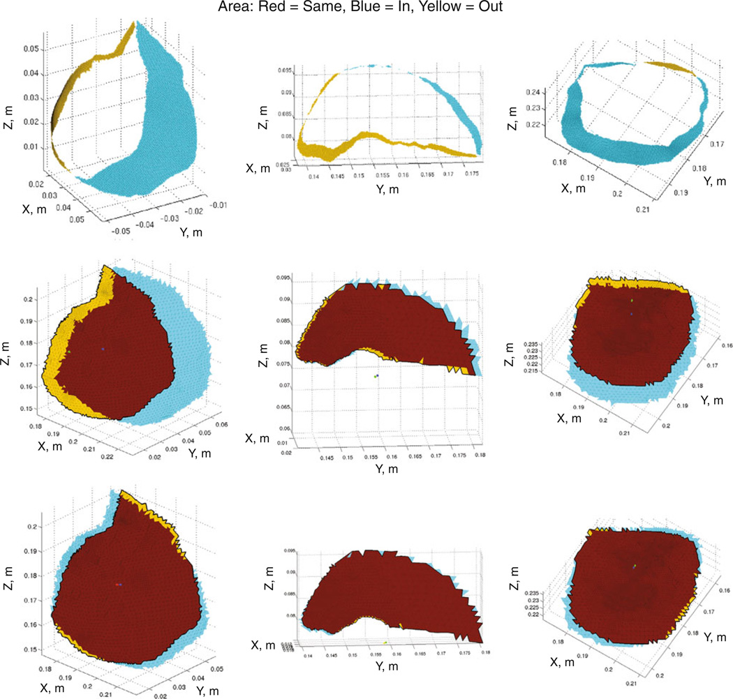
Table 3 also describes the orientations converged upon by SM optimization of the objective function (columns 5, 6, 7, 8), which can be directly compared to the best model-fit of the surgical parameters (columns 9, 10, 12, 13), thus providing displacement-based quantification of the optimization frame-work with respect to the intraoperatively measured LRS deformation data. Figure 6 displays three examples (cases 2, 5, and 6 in each column, respectively) of the area classification mapping produced from the LRS data (top row), the best model-fit orientations of the surgical parameters (middle row), and the SM optimization orientations minimizing brain shift (bottom row). Table 4 records the quantification of the measures displayed in Fig. 6. It was found that the SM optimization orientations correspond to an overall reduction in brain shift in comparison with the LRS deformation data on the basis of both change of cortical surface area and lateral shift of the tumor center.
Fig. 6.
Area classification maps. Area classification maps wherein yellow denotes area leaving the craniotomy, blue shows area entering the craniotomy, and red indicates cortical surface area staying visible. Columns correspond to cases 2, 5, and 6, which span the range of tumor volumes. The 1st row consists of the LRS area mapping, 2nd row the best model-fit of the surgical parameters, and 3rd row the SM optimized orientation
Table 4.
Quantitative area metrics and the magnitude of tumor center lateral displacement
| Measure | Case 1 | Case 2 | Case 3 | Case 4 | Case 5 | Case 6 |
|---|---|---|---|---|---|---|
| Craniotomy area (cm2) | 42.3 | 23.8 | 10.5 | 10.6 | 5.8 | 15.5 |
| % Change in area* (LRS) | 41 % | 47 % | 16 % | 31 % | 21 % | 32 % |
| % Change in area* (Best surgical) | 44 % | 71 % | 21 % | 20 % | 13 % | 33 % |
| % Change in area* (SM optimized) | 19 % | 19 % | 12 % | 9 % | 3 % | 11 % |
| Lateral shift (mm) (Best surgical) | 8.5 | 13.8 | 2.4 | 1.5 | 0.6 | 5.0 |
| Lateral shift (mm) (SM optimized) | 1.0 | 1.2 | 1.6 | 0.2 | 0.4 | 0.8 |
Change in area ΔA = (AEnter + ALeave)/A0
With respect to the six cases, the average differences between orientation angles (ϕ and θ) determined using our model-derived SM optimized prediction and the best model-fit of the surgical parameters as determined from the LRS deformation data [and as executed by (RCT)] were 8.2° ± 3.7° and 14.7° ± 9.3°, respectively, for head rotation and tilt. It should be noted that the fitted LRS deformation data are not necessarily the optimum for intraoperative shift minimization, but rather the orientation selected by (RCT) as optimum (an experiential orientation thought to minimize shift).
Discussion
Given the distinctive nature of the cortical surface area with its pattern of blood vessels and sulci that serve as visual landmarks of location, its classification into regions newly visible, shifting out of view, or remaining visible constitutes a logical and significant metric to qualify shift. Area remaining visible corresponds to maintaining the presence of landmarks conducive to surgical guidance, suggesting its maximization. Proper model area classification of cortical surface visible in the craniotomy requires fidelity in the LRS deformation data. The target landmark points used to assess shift prediction are sparse measures and do not represent a comprehensive measure of fidelity. Consequently, it is difficult to use their evaluation for the sole assessment of optimization performance. Trying to maintain the original area within the craniotomy may not physically be a complete measure but is more comprehensive. However, further investigation of more clinical cases toward this end is necessary to determine its robustness and does serve as an important limitation to this work at this time. Nevertheless, the results reported here using these shift metrics do suggest considerable strength to the framework.
Closer examination of the shift prediction percentages showed the temporal lobe cases had better predictions because the homologous points were observed to displace intraoperatively more uniformly in direction than in the other cases which the model less easily matched. The frontal lobe cases had large movements of tissue into the resection cavities. Case 6 was unusual in that the tumor lay close to the falx and considerable contraction of the surrounding cortical surface into the resection cavity occurred, more so than in any other case. With the recent work intraoperatively, it has been observed that model-predicted displacements provided by our framework do not completely account for contraction toward the resection cavity, which is caused by the removal of the supportive tumor mass, as well as the stress-relieving tumor debulking process [14]. Visual examination of the cortical area distributions in Fig. 3 demonstrates this contraction of tissue. Since collapsing of tissue into a resection cavity appears an inevitable surgical phenomenon upon removal of the supportive tumor mass, the addition of debulking stress seems a sound direction to pursue to attain a more accurate measure of area remaining visible. Modeling the resection cavity decompression through application of these debulking stresses is currently under investigation [19,20], but validation of the shift predictions by the model is still an area of future work.
As reported in the Results, the average model cortical shift for each case in Table 3 intriguingly shows high fidelity to the LRS deformation data if the model is allowed to search the surgical parameter space to achieve the best-model fit of brain shift based on available data. Similarly, the SM optimized orientations’ average overall cortical shift of 9.3 mm compared with the best surgical match of 12.1 mm in Table 3 suggests that optimization of the parameter space could reduce shift procedurally by about 23 % overall. Furthermore, the general lateral shift reduction of the cortical landmarks was 63 %. Case 2 demonstrated an 8 mm shift reduction, or 44 % overall, with a 77 % reduction in lateral shift. Table 4 shows the average reduction in change of cortical area in the craniotomy amounted to 60 % less change relative to the processed LRS deformation data. The average lateral shift of the tumor center in comparison with the best model-fit of the surgical parameters saw a similar reduction of 70 % in shift across cases. The reduction in change of cortical area can be attributed to the displacements being more downward along the surgical ‘approach’ vector than lateral to it. This is corroborated by the 60–70 % reduction in lateral shift of the cortical surface landmarks and the tumor center.
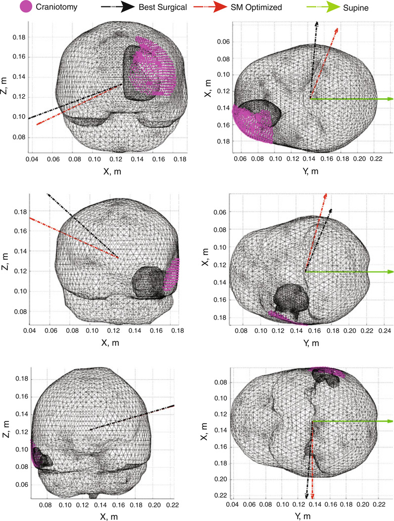
Comparison of the SM optimized orientations with the best fit of the surgical parameter space highlights several features of note. The angular differences reported suggest better agreement of the optimal orientation with the surgical orientation in the rotation angle ϕ than in the tilt angle θ. This suggests that minimization of the anterior–posterior (A-P) shift of the brain on the part of [RCT] may be a higher priority in selecting orientation. Accordingly, [RCT] likely chooses to tilt the head to facilitate ease of surgical access and alleviate patient safety concerns with jugular venous return blood flow rather than to minimize shift per se. The orientation angles also suggest an overall trend whereby tumor locations that vary from frontal to temporal lobe indicate a lateral decubitus position on the side contralateral to the tumor hemisphere is desirable from the standpoint of reducing A-P shift. This position uses the support of the falx membrane as a natural constraint to prevent displacement across the falx while rotating the head sufficiently perpendicular to gravity to minimize the A-P shift. Examination of tilt angles for the optimal orientations revealed a relationship between the center of the craniotomy and the volumetric centroid of the brain given a lateral decubitus position. For tumors above the level of the brain centroid (approximately between the two hemispheres at the level superior to the ears), the head should be tilted down toward the shoulder contralateral to the tumor, and for tumors below that level in general, the head should be tilted up. Thus, the Table 3 angular data, shown in Fig. 7 for cases 2, 4, and 5, suggest a reasonable approximation of the head rotation angle would be to align gravity along the vector from the craniotomy center to the brain centroid.
Fig. 7.
Patient orientations, cases 2, 4, and 5 shown with the supine orientation (green), the best model-fit of the surgical parameters as executed by [RCT] (black), and the SM optimized orientation (red) from the angular data in Table 3
Minimal shift of the tumor center appears to occur when the area distribution is located concentrically within the craniotomy. The optimal atlas orientations in Fig. 6 provide support for this idea. The area entering and leaving the field of view of the craniotomy displays a notable degree of symmetry about the craniotomy perimeter in their distributions and quantity. The perimeter of the shape formed by the area entering and the area remaining the same in the field of view exhibits an intriguing degree of concentricity with the craniotomy perimeter. This concentricity is apparent in Fig. 6. Measurement of shift of the tumor center during surgery would be challenging, whereas movements of the cortical surface are readily achieved. The coincidence of the occurrence of minimum lateral shift with a concentric area distribution suggests a possible method of ascertaining how close to optimum a surgical orientation manages to achieve. With area entering with a symmetric distribution and little area leaving for the optimal orientation, the implication is that the optimal orientation likely occurs where there is an increased amount of compression of the tumor surface by the surrounding healthy tissue. This hypothesis could be tested in future work.
Conclusions
Conceptualizing a framework whereby biomechanical models could suggest orientations to the surgeon to influence the impact of shift seems promising. Furthermore, the work presented here addresses the deformation correction problem associated with image-guided neurosurgery from the perspective of preoperative planning. It is intriguing in that this work recasts surgical simulation from a trial-and-error process to one where options are presented to the surgeon arising from an optimization of surgical goals (in this case minimization of brain shift). In the future, one could possibly envision situations where the surgeon may desire brain shift to help illuminate an approach into the disease focus. Ultimately, this represents a very different realization of guidance whereby computer models can assist in the delivery of therapy by providing additional predictable surgical manipulations. To our knowledge, this is the first realization of an evaluative tool for surgical planning that attempts to optimize surgical approach by means of shift minimization in this manner. The results presented demonstrate exciting clinical potential for aiding surgeons in the delivery of surgical therapies for tumors.
Acknowledgments
This research was supported by NIH-National Institute for Neurological Disorders and Stroke Grant # R01NS049251. The authors wish to thank the participating neurosurgeon RCT and the operating room staff for their time and assistance
Appendix
Spherical coordinate system reference
For head orientation purposes, a spherical coordinate system was used. When overlaid on a set of Cartesian axes, the default orientation of the patient lying supine corresponds to the gravity vector being aligned along the positive y axis while possessing rotation angles in spherical coordinates of [0°] for phi and theta. For purposes of nomenclature, the angle phi is considered to indicate the degree of rotation of the head, whereas theta is considered to specify tilt. A positive rotation in phi of +90° for a left hemisphere tumor, therefore, results in the patient lying in a lateral decubitus position on the side contralateral to the tumor with the gravity normal to the plane of the falx. From this position, a positive theta tilts the head down, and a negative theta tilts the head up.
Footnotes
Conflict of interest The authors declare that they have no conflict of interest
Contributor Information
Aaron M. Coffey, Department of Biomedical Engineering, Vanderbilt University, P.O. 1631, Station B, Nashville, TN 37235, USA
Michael I. Miga, Email: michael.miga@vanderbilt.edu, michael.i.miga@vanderbilt.edu, Department of Biomedical Engineering, Vanderbilt University, P.O. 1631, Station B, Nashville, TN 37235, USA; Department of Neurological Surgery, Vanderbilt University Medical Center, T-4224MCN/VUMC, Nashville, TN 37232 2380, USA; Department of Radiology and Radiological Sciences, Vanderbilt University Medical Center, CCC-1106MCN/VUMC, Nashville, TN 37232 2675, USA.
Ishita Chen, Department of Biomedical Engineering, Vanderbilt University, P.O. 1631, Station B, Nashville, TN 37235, USA.
Reid C. Thompson, Department of Neurological Surgery, Vanderbilt University Medical Center, T-4224MCN/VUMC, Nashville, TN 37232 2380, USA
References
- 1.Hartkens T, Hill DLG, Castellano-Smith AD, Hawkes DJ, Maurer CR, Martin AJ, Hall WA, Liu H, Truwit CL. Measurement and analysis of brain deformation during neurosurgery. IEEE Trans Med Imaging. 2003;22(1):82–92. doi: 10.1109/TMI.2002.806596. [DOI] [PubMed] [Google Scholar]
- 2.Roberts DW, Hartov A, Kennedy FE, Miga MI, Paulsen KD. Intraoperative brain shift and deformation: a quantitative analysis of cortical displacement in 28 cases. Neurosurgery. 1998;43(4):749–758. doi: 10.1097/00006123-199810000-00010. [DOI] [PubMed] [Google Scholar]
- 3.Hastreiter P, Rezk-Salama C, Soza G, Bauer M, Greiner G, Fahlbusch R, Ganslandt O, Nimsky C. Strategies for brain shift evaluation. Med Image Anal. 2004;8(4):447–464. doi: 10.1016/j.media.2004.02.001. [DOI] [PubMed] [Google Scholar]
- 4.Nimsky C, Ganslandt O, Cerny S, Hastreiter P, Greiner G, Fahlbusch R. Quantification of, visualization of, compensation for brain shift using intraoperative magnetic resonance imaging. Neurosurgery. 2000;47(5):1070–1079. doi: 10.1097/00006123-200011000-00008. [DOI] [PubMed] [Google Scholar]
- 5.Butler WE, Piaggio CM, Constantinou C, Niklason L, Gonzalez RG, Cosgrove GR, Zervas NT. A mobile computed tomographic scanner with intraoperative and intensive care unit applications. Neurosurgery. 1998;42(6):1304–1310. doi: 10.1097/00006123-199806000-00064. [DOI] [PubMed] [Google Scholar]
- 6.Letteboer MMJ, Willems PWA, Viergever MA, Niessen WJ. Brain shift estimation in image-guided neurosurgery using 3-D ultrasound. IEEE Trans Biomed Eng. 2005;52(2):268–276. doi: 10.1109/TBME.2004.840186. [DOI] [PubMed] [Google Scholar]
- 7.Ji SB, Wu ZJ, Hartov A, Roberts DW, Paulsen KD. Mutual-information-based image to patient re-registration using intraoperative ultrasound in image-guided neurosurgery. Med Phys. 2008;35(10):4612–4624. doi: 10.1118/1.2977728. [DOI] [PMC free article] [PubMed] [Google Scholar]
- 8.Castellano-Smith AD, Hartkens T, Schnabel JA, Hose DR, Liu AK, Hall WA, Truwit CL, Hawkes DJ, Hill DLG. Constructing patient specific models for correcting intraoperative brain deformation. In: Niessen WJ, editor. Medical image computing and computer assisted intervention. vol 2008. Utrecht: Springer; 2001. pp. 1091–1098. [Google Scholar]
- 9.Dumpuri P, Thompson RC, Cao AZ, Ding SY, Garg I, Dawant BM, Miga MI. A fast and efficient method to compensate for brain shift for tumor resection therapies measured between preoperative and postoperative tomograms. IEEE Trans Biomed Eng. 2010;57(6):1285–1296. doi: 10.1109/TBME.2009.2039643. [DOI] [PMC free article] [PubMed] [Google Scholar]
- 10.Ferrant M, Nabavi A, Macq B, Black PM, Jolesz FA, Kikinis R, Warfield SK. Serial registration of intraoperative MR images of the brain. Med Image Anal. 2002;6(4):337–359. doi: 10.1016/s1361-8415(02)00060-9. [DOI] [PubMed] [Google Scholar]
- 11.Hagemann A, Rohr K, Stiehl HS, Spetzger U, Gilsbach JM. Biomechanical modeling of the human head for physically based, nonrigid image registration. IEEE TransMed Imaging. 1999;18(10):875–884. doi: 10.1109/42.811267. [DOI] [PubMed] [Google Scholar]
- 12.Skrinjar O, Nabavi A, Duncan J. Model-driven brain shift compensation. Med Image Anal. 2002;6(4):361–373. doi: 10.1016/s1361-8415(02)00062-2. [DOI] [PubMed] [Google Scholar]
- 13.Lunn KE, Paulsen KD, Liu FH, Kennedy FE, Hartov A, Roberts DW. Data-guided brain deformation modeling: evaluation of a 3-D adjoint inversion method in porcine studies. IEEE Trans Biomed Eng. 2006;53(10):1893–1900. doi: 10.1109/TBME.2006.881771. [DOI] [PubMed] [Google Scholar]
- 14.Chen I, Coffey AM, Ding SY, Dumpuri P, Dawant BM, Thompson RC, Miga MI. Intraoperative brain shift compensation: accounting for dural septa. IEEE Trans Biomed Eng. 2011;58(3):499–508. doi: 10.1109/TBME.2010.2093896. [DOI] [PMC free article] [PubMed] [Google Scholar]
- 15.D’Haese PF, Duay V, Merchant TE, Macq B, Dawant BM. Medical image computing and computer-assisted intervention— Miccai. Pt 2. Vol. 2879. Berlin: Springer; 2003. Atlas-based segmentation of the brain for 3-dimensional treatment planning in children with infratentorial ependymoma; pp. 627–634. [Google Scholar]
- 16.Dumpuri P, Thompson RC, Dawant BM, Cao A, Miga MI. An atlas-based method to compensate for brain shift: preliminary results. Med Image Anal. 2007;11(2):128–145. doi: 10.1016/j.media.2006.11.002. [DOI] [PMC free article] [PubMed] [Google Scholar]
- 17.Miga MI, Paulsen KD, Lemery JM, Eisner SD, Hartov A, Kennedy FE, Roberts DW. Model-updated image guidance: initial clinical experiences with gravity-induced brain deformation. IEEE Trans Med Imaging. 1999;18(10):866–874. doi: 10.1109/42.811265. [DOI] [PubMed] [Google Scholar]
- 18.Paulsen KD, Miga MI, Kennedy FE, Hoopes PJ, Hartov A, Roberts DW. A computational model for tracking subsurface tissue deformation during stereotactic neurosurgery. IEEE Trans Biomed Eng. 1999;46(2):213–225. doi: 10.1109/10.740884. [DOI] [PubMed] [Google Scholar]
- 19.Coffey AM. Prediction of patient orientation with minimized lateral shift for brain tumor resection therapies. Nashville: Vanderbilt University; 2010. [Google Scholar]
- 20.Coffey AM, Garg I, Miga MI, Thompson RC. An evaluative tool for preoperative planning of brain tumor resection. In: Wong KW, Miga MI, editors. SPIE medical imaging 2010: visualization, image-guided procedures, and modeling. Vol. 7625. San Diego: SPIE; 2010. pp. 762531-1–762531-12. [Google Scholar]


