Abstract
This study characterized thoracoabdominal response to posterolateral loading from a seat-mounted side airbag. Seven unembalmed post-mortem human subjects were exposed to ten airbag deployments. Subjects were positioned such that the deploying airbag first contacted the posterolateral thorax between T6 and L1 while stationary (n = 3 × 2 aspects) or while subjected to left lateral sled impact at ΔV = 6.7 m/s (n = 4). Chestband contours were analyzed to quantify deformation direction in the thoracic x–y plane (zero degrees indicating anterior and 180° indicating posterior), magnitude, rate, and viscous response. Skeletal injuries were consistent with posterolateral contact; visceral injuries consisted of renal (n = 1) or splenic (n = 3) lacerations. Deformation direction was transient during sled impact, progressing from 122 ± 5° at deformation onset to 90° following maximum deflection. Angles from stationary subjects progressed from 141 ± 9° to 120°. Peak normalized deflections, peak rates, and VCmax ranges were 0.075 – 0.171, 3.7 – 12.7 m/s, and 0.3 – 0.6 m/s with stationary airbag, respectively; ranges were 0.167 – 0.297, 7.4 – 18.3 m/s, and 0.7 – 3.0 m/s with airbag sled impact, respectively. Peak deflections were measured at angles between 99° – 135° and 98° – 125° for stationary and dynamic conditions, respectively. Because of deflection angle transience and localized injury response, both posterolateral and lateral injury metrics may be required for this boundary condition. Contrasted with flat rigid or anterolateral loading, biomechanical response to side airbag interaction may be augmented by peak normalized deflection or VCmax at 130°.
Keywords: Biomechanics, Side airbags, Sled impact, Chestbands, Thorax Injuries, Oblique Loading
INTRODUCTION
Because the motor vehicle crash environment subjects occupants to a diverse set of loading modalities, many studies have examined the relationship between thoracoabdominal biomechanics and different boundary conditions. Primate specimens and post mortem human subjects (PMHS) were exposed to lateral thoracic and abdominal loading with flat and wedge-shaped impactors (Stalnaker et al., 1973). Specimens subjected to dynamic whole-body impacts sustained greater injury severity than stationary specimens with “equivalent” biomechanical input. Using a 10 kg flat rigid pendulum impactor, thoracoabdominal response to lateral impact was examined in primates, canines, and PMHS (Nusholtz et al., 1980). Examining visceral biomechanical response via cineradiography, it was observed that in vivo subjects sustained greater injury severity than post-mortem subjects.
Rabbit specimens (n = 117) were subjected to lateral abdominal impacts with parametric variation of piston velocity and compression magnitude (Rouhana et al., 1985). With velocities of 3 – 15 m/s and 10 – 50% compression, it was demonstrated that visceral injury risk was related to the product of forced compression and velocity. The Abdominal Injury Criterion (AIC) was proposed with AIC = 4.9 – 5.5 m/s for right- and left-side impact representing 50% risk of serious injury, i.e., Abbreviated Injury Scale (AIS) ≥ 3. Porcine specimens (n = 14) and PMHS (n = 14) were subjected to rigid 23.4 kg pendulum impacts to the lateral thorax (Lau and Viano, 1986; Viano et al., 1989a; Viano, 1989). Free pendulum velocity was 4.5, 6.7, or 9.4 m/s. The relationship between peak compression, deformation rate, and observed risk of injury was reported for these larger subjects as the Viscous Criterion (VC). Similar to the AIC, the VC is the instantaneous product of compression and deformation rate. Tolerance for lateral thoracic impact was proposed as VCmax = 1.5 m/s, representing 25% risk of serious injury.
Utilizing drop tests, PMHS were exposed to flat rigid impacts, padded pelvis and thorax offsets, and contoured interior door geometry (Tarriere et al., 1979). Chest compression equal to 30% of full chest breadth corresponded to serious injury. Sled tests utilizing PMHS were conducted at velocities between ΔV = 25 and 43 km/h with either a flat rigid wall or contoured padded structure (Kallieris et al., 1981; Melvin et al., 1976). Polystyrene foam, fiberglass, and APR padding materials were investigated; the accelerometer response was reduced by presence of padding. Further injury analysis found that average AIS was decreased by approximately one level with padding and that wall reaction force was decreased by 15%. Using porcine specimens, the influence of a lateral boundary gap of width 20.3 cm was examined in a sled environment (Rouhana and Kroell, 1989). In impacts between ΔV = 7.2 and 15.0 m/s, the gap boundary condition was found to significantly increase the severity of liver, kidney, and spleen injuries. Similar findings have been noted when the boundary condition includes a positive abdominal or armrest-type offset (Cavanaugh et al., 1996; Kuppa et al., 2003). In these studies, PMHS were subjected to impact velocities between ΔV = 6.7 and 9.1 m/s.
In addition to the physical characteristics of the load application, loading direction with respect to the anatomy represents an important parameter. Recent studies of oblique loading to the thorax characterized biomechanical and injury response with emphasis on comparisons between traditional loading, i.e., anterior and/or lateral, and anterolateral loading. Comparing PMHS response to loading directions of anterior, lateral, and 45° with respect to mid-sagittal plane, it was reported that a single parameter such as uniaxial deflection may be insufficient to characterize thoracic response to blunt impact (Nusholtz et al., 1980), although deflections were not reported. Other pendulum impacts performed at 60° (Viano, 1989) were observed to produce force magnitudes similar to earlier lateral, i.e., 90°, impacts (Eppinger et al., 1978). However the obliquely loaded thorax, i.e., 15°, demonstrated greater deflections compared to anterior sternal thoracic loading when equal impactor velocities were compared (Yoganandan et al., 1996; Yoganandan et al., 1997). Similarly, reduced stiffness and greater deflections were observed under oblique loading, i.e., 60°, compared to lateral thoracic loading when equal energy impacts were compared (Shaw et al., 2006). Internal and external thoracic deformation response was also investigated in anterior, lateral, and 60° loading for relationships to observed skeletal injury outcomes (Trosseille et al., 2008; Trosseille et al., 2009). An increased number of rib fractures were reported in lateral compared to oblique loading.
These anterolateral loading modalities have been demonstrated in full scale side impact vehicle crash tests into rigid poles (Pintar et al., 2007). Consequently, anterolateral thoracoabdominal loading has been studied in a dynamic sled environment at ΔV = 6.7 m/s (Yoganandan and Pintar, 2008; Yoganandan et al., 2008). Using sled boundary conditions at 20° or 30° with respect to lateral, chest deflections under oblique loading were found to exceed deflections from lateral loading at similar ΔV (Maltese et al., 2002). Because the thorax and abdomen are asymmetric and heterogeneous, differing impact angles load anatomical structures in manners unique to each boundary condition. Thus injury criteria specific to oblique boundary conditions may be required.
Few studies have attempted to characterize the biomechanical response of the thorax and/or abdomen to posterolateral loading. One study varied impact angle posteriorly by 15° for anthropomorphic test device validation (Morgan and Waters, 1980). While crashes resulting in 4 – 5 or 7 – 8 o’clock principal directions of force appear to be rarer than other lateral impact variants (Dischinger et al., 1993; Zaouk et al., 2001), seat-mounted side airbags may provide a common posterolateral thoracic and abdominal loading mechanism. Torso-interacting airbags are available in up to 70% of automobiles and light trucks (IIHS, 2009); the vast majority of these are mounted within the seat back and posterolateral to the occupant. While deformations in the posterolateral region were found to result from side airbag deployment in a preliminary PMHS chestband analysis (Hallman et al., 2009), the interaction between deploying seat-mounted airbag and the posterolateral thorax has not been delineated fully. Therefore, the objective of the present study was to characterize the biomechanical and injury response of the thorax and abdomen to a posterolateral loading modality similar to that found in a real vehicle environment.
METHODS
The protocol was designed to characterize thoracoabdominal response to seat-mounted torso-interacting side airbags.1 Stationary and dynamic (sled) test setups were developed in which posterolateral contact from torso side airbags occurred. Injury response from two dynamic tests has been described in lesser detail previously (Hallman et al., 2010). An airbag was selected from a subset of popular vehicles as determined by U.S. sales (Automotive News, 2008). The chosen airbag inflated from a spiral fold pattern to a volume of approximately 11 liters within 14 ms following activation. The bag fabric had no vent holes, extended approximately 44 cm from the inflator, and measured 40 cm in the occupant z-axis. To characterize the potential loading capabilities of the airbag, a previous study deployed a variety of bags against an instrumented rigid surface 6 cm away (Hallman et al., 2009). The chosen airbag exerted 4 kN peak force against this surface, which was the maximum tested and over 60% greater than the mean.
Subject Preparation
Unembalmed PMHS were screened for HIV and Hepatitis A, B, and C. Anthropomorphic data and pre-test radiographs were obtained according to established procedures (Pintar et al., 1997). Specimens were dressed in tight-fitting leotards and masked to cover the head and face. Following surgical exposure of the femoral artery within the femoral triangle, a Foley catheter was inserted proximally through the iliac artery and fixed in the abdominal aorta by inflating the balloon. A tracheostomy was performed and pulmonary edematous fluid was removed. Carotid arteries were occluded by ligature. Accelerometers were rigidly fixed to the spine at the locations of T1, T12, and the sacrum; axes were in accordance with SAE J211.
Experimental Procedure
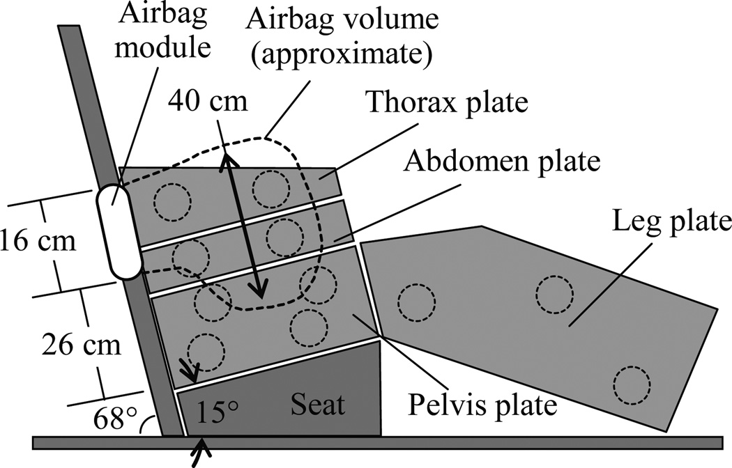
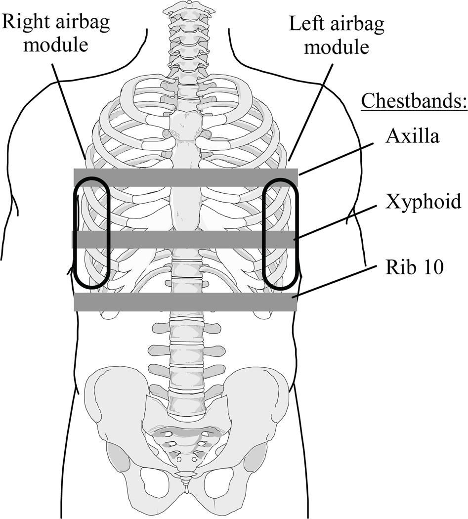
PMHS were subjected to stationary airbag deployment or dynamic lateral impact with close-proximity airbag boundary condition. In both instances, subjects were placed on a Teflon-coated bench seat with 2.5 cm square tubular supports for the lumbar and thoracic regions. The seat assembly included a 15° seat pan angle and a 68° seat back angle (Fig. 1). Further details have been described in the literature (Yoganandan et al., 2007). Prior to testing, chestbands were placed on the torso circumferentially. For stationary tests, one 59-channel chestband was placed at the xyphoid level. In dynamic tests, two 59-channel chestbands were placed at levels corresponding to the xyphoid and tenth rib (Fig 2). In one dynamic test, a chestband was placed at the axilla level in lieu of the tenth rib level. Using palpation, the band locations overlying the spine and sternum centerlines were determined. Chestbands were wrapped with metallic shielding and sealed with conductive adhesive tape. This treatment minimized signal interference from electrostatic discharge induced by rapid airbag fabric deployment. Shielding was overlaid with a cotton garment to maintain realistic interaction between the subject and the deploying airbag. After the chestbands and overlying materials were in place, subjects were positioned upright on the seat assembly in a normal forward-facing posture. Care was taken to ensure that the head Frankfort plane was horizontal, legs were extended forward in a normal driving posture, and the dorsal spine maintained normal curvature. To maximize thoracic exposure to airbag deployment characteristics, both arms were oriented forward and away from the lateral thorax. This maintained an unprotected thorax throughout the event. Specimen vasculature was pressurized to normal mean arterial pressure (approximately 90 mmHg) with a heparin and dye solution by means of the Foley catheter; lungs were exercised immediately prior to testing and left open to atmosphere.
FIGURE 1.
Bench seat apparatus with seat-mounted side airbag placement. Additional details provided in Yoganandan et al. (2007)
FIGURE 2.
Chestband locations with respect to specimen anatomy and airbag module locations; only xyphoid chestband was placed on stationary test specimens.
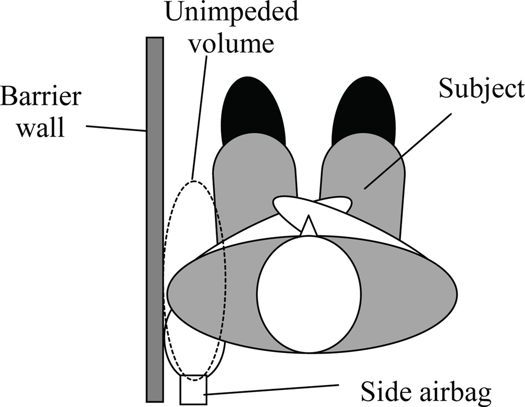
For stationary airbag deployments, a rigid wall was attached to the seat assembly such that the superior edge was at a height of 450 mm above the seat. This corresponded to a level just inferior to the shoulder complex. The torso side airbag was mounted approximately 130 mm away from the wall. Subjects were positioned adjacent to the wall with the unmodified folded airbag approximately 1.0 cm from the posterolateral thorax between the T6 and L1 levels. No trim pieces or seat subcomponents were included. The airbag was the only source of energy to interact with the subject. Left- and right-side deployments were performed on each subject.
For dynamic impacts, the bench seat and back support were fixed to the platform of an acceleration sled with pneumatic actuation and hydraulic control (ServoSled®, Seattle Safety, Kent, WA). A four-plate force-instrumented load wall configuration was located on the left end of the seat assembly (Fig. 1) and has been described elsewhere (Yoganandan et al., 2007). Wall adjustments were made to ensure the superior edge of the thorax plate corresponded to a level just inferior to the shoulder complex for all specimens. Thus, no shoulder engagement occurred. The unmodified torso side airbag was mounted posterior to the subject at a distance of 150 mm from the wall. The subjects were positioned 400 mm from the load wall, a distance sufficient for the sled to achieve and maintain ΔV = 6.7 m/s between airbag activation and wall contact. Sled acceleration was recorded using a uniaxial accelerometer. The side airbag was activated when the outboard edges of the module and subject torso were coincident in the frontal plane. This deployment time ensured that the deploying airbag interacted with the posterolateral region of the subject thorax and abdomen.
Ten PMHS tests were completed. Three PMHS were subjected to stationary airbag deployment with both aspects exposed, and four PMHS were subjected to dynamic lateral impacts with airbag (Table 1). Mean subject age was 60.6 yrs; mean height and mass were 170 cm and 72.1 kg. Following testing, radiographs were taken and full-dissection necropsy was performed by a board-certified pathologist to obtain a detailed assessment of trauma to hard and soft tissues. Injuries were recorded and scaled in accordance with the AIS 2005 edition (AAAM, 2005).
TABLE 1.
Specimen specifications and test configuration.
| Specimen | ID | Config | Gender | Age (yrs) |
Height (cm) |
Weight (kg) |
Chest depth* (cm) |
Chest breadth* (cm) |
|---|---|---|---|---|---|---|---|---|
| 1 | S-1 | Static, L | M | 37 | 166 | 64 | 27.5 | 34.3 |
| S-2 | Static, R | |||||||
| 2 | S-3 | Static, L | M | 83 | 174 | 86 | 29.7 | 38.4 |
| S-4 | Static, R | |||||||
| 3 | S-5 | Static, R | F | 50 | 164 | 57 | 22.9 | 30.8 |
| S-6 | Static, L | |||||||
| 4 | D-1 | Dynamic | F | 81 | 150 | 50 | 25.7 | 33.7 |
| 5 | D-2 | Dynamic | M | 64 | 176 | 84 | 28.9 | 38.9 |
| 6 | D-3 | Dynamic | M | 63 | 162 | 56 | 24.9 | 30.5 |
| 7 | D-4 | Dynamic | M | 46 | 201 | 108 | 29.5 | 41.3 |
Measured at the xyphoid level.
Data Collection and Processing
All signals were gathered at 12.5 kHz and processed in accordance with SAE J211 specifications. High speed videography was recorded at a minimum of 2.5 kHz from four views: frontal, front oblique, overhead, and rear oblique.
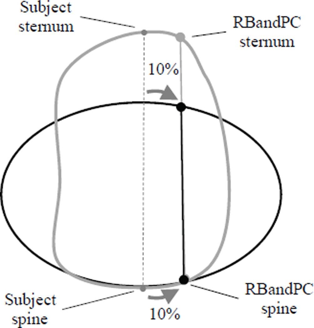
Chestband signals were filtered according to CFC180 to remove airbag electrostatic interference and processed using RBandPC (ver. 3.0a). As defined in RBandPC, the spine and sternum locations represent unique contour boundary conditions. The spine location represents the contour origin. The sternum location is constrained at y = 0 (as defined by spine) but may rotate and translate in the subject x-axis. For solution stability in posterolateral loading, artificial spine and sternum locations were assigned in RBandPC processing as follows. Contour locations overlying subject spine and sternum locations were identified. When imported into RBandPC, artificial spine and sternum locations were offset from subject spine and sternum in the contralateral direction by 10% of total chestband circumference (Fig. 3). This methodology ensured that no boundary artifacts were generated by posterolateral loading in the vicinity of the subject spine location. Contours were generated at frequencies of 12.5 kHz throughout the event.
FIGURE 3.
RBandPC analysis methodology for chestband contour generation with side airbag boundary condition.
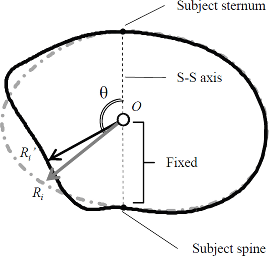
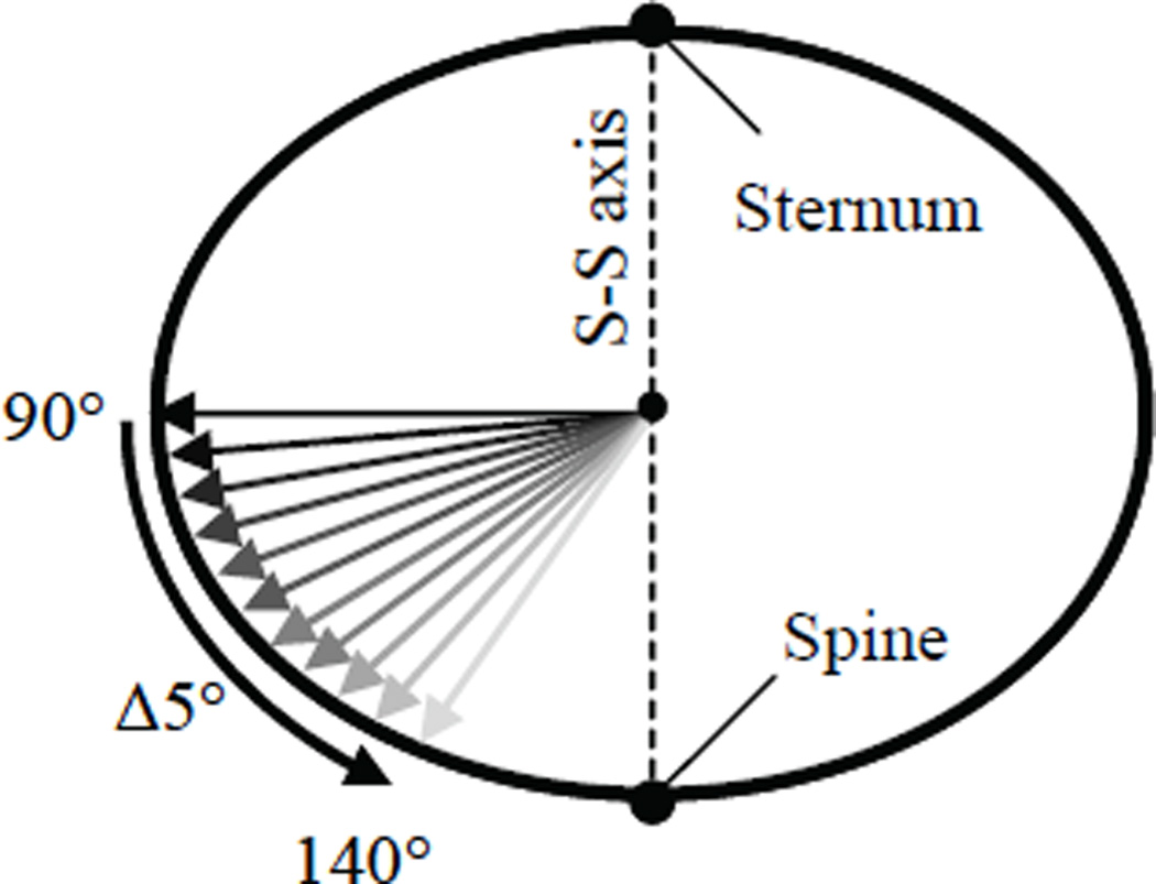
Contour outputs from RBandPC were postprocessed using MATLAB (R2008a). The spine and sternum contour locations were returned to the centerlines of the subject spine and sternum; the spine-sternum (S-S) axis was defined by these anatomical locations (Fig. 4). Contour origin (O) was defined as the midpoint between the spine and sternum contour locations in the undeformed state (t = 0). As deformation progressed, O remained coincident with the S-S axis and maintained a fixed distance from the spine. Vectors for deformation measurement were defined between O and points around the perimeter of the contour. Discrete points were obtained at approximately 2 mm intervals circumferentially (Ri). Deflections were quantified as the scalar subtraction of the instantaneous vector length O’Ri’ from the initial undeformed vector length ORi. Deflections were normalized to chest breadth and a CFC 180 filter was applied. The deformation direction for each point Ri was defined as the non-reflex angle (θ = 0 – 180°) between the S-S axis and each initial vector ORi, measured from the forward (anterior) direction. Left-side impacts were measured in the counterclockwise direction; right-side impacts were measured in the clockwise direction. Time traces of normalized deflection vectors were examined between θ = 90° and 140°. Deflection rate and its instantaneous product with normalized deflection, i.e., VC (Lau and Viano, 1986), were also calculated.
FIGURE 4.
Chestband post-processing methodologies for oblique deflection analysis.
RESULTS
Airbag Behavior
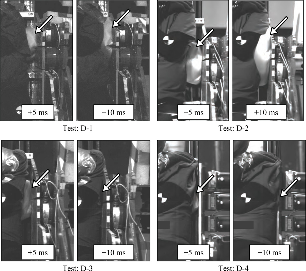
High-speed videography was examined to verify airbag boundary conditions. In stationary deployments, the inflating airbag first contacted the posterolateral torso approximately between the T6 and L1 levels. As inflation progressed, the bag fabric unfolded in the forward and lateral directions around the torso where the bag contacted the rigid boundary (Fig. 5). In these tests, a portion of airbag volume “escaped” in the inferior or superior direction, potentially reducing the membrane loading applied to the subject. For dynamic tests, the observed airbag deployment sequence is shown in Figure 6. PMHS were first contacted by the airbag in a manner similar to stationary deployments. Following initial contact, the airbag fabric unfolded forward and lateral around the torso into the space between the subject and the load wall. Relative motion continued between the subject and the impact apparatus. This motion narrowed the space between the torso and the load wall as the airbag was simultaneously expanding within this space. Shown in Figure 7 are videographic frames from the four dynamic tests and the degree of forward airbag expansion into the lateral space. Despite similar deployment conditions, deployment variability was observed. In tests D-1 and D-2, the bag fabric completely surrounded the thoracoabdominal region and, in D-2, prevented the thorax from directly contacting the load wall. Tests D-3 and D-4 exhibited less expansion before the moving torso obstructed further forward movement; in these tests airbag coverage extended approximately to the mid-axillary line. As load wall interaction was maximized at the end of airbag gas generation, rigid contact occurred through the deflated fabric.
FIGURE 5.
Stationary airbag deployment scenario.
FIGURE 6.
Dynamic late deployment side airbag scenario: (a) prior to airbag activation, (b) posterolateral thoracoabdominal interaction with airbag inflation, and (c) load wall interaction with subject following airbag deployment.
FIGURE 7.
Still frames from videography (frontal view) depicting variability in airbag deployment expansion for the four dynamic occupant tests. Duration following airbag activation is noted. Arrows indicate visible airbag fabric.
Injury Observations
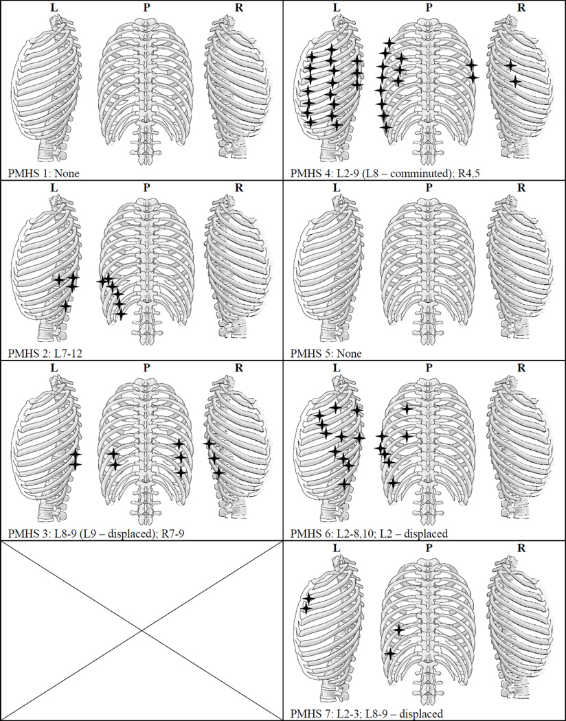
Shown in Table 2 are the injuries observed during necropsy and AIS assessment. Skeletal injuries were observed in PMHS 2 and 3 (stationary tests) and PMHS 4, 6, and 7 (dynamic tests). Rib fractures are indicated anatomically in Figure 8. In stationary tests, rib fractures were noted in posterolateral region between ribs 7 – 12; skeletal injury was AIS 3 for two of three tests. In dynamic tests, rib fractures ranged from none (PMHS 5) to twenty rib fractures (bilateral) with probable flail chest (PMHS 4). PMHS 7, a dynamic test subject, was subjected to two impacts due to a malfunction in the airbag deployment test setup. Palpation was performed prior to and following the second impact; fractures were noted following the second test but were not noted following the first test. Further, post-test necropsy indicated only four rib fractures to this subject.
TABLE 2.
Injury Results
| PMHS | Config. | Injury Description | Skeletal AIS | Visceral AIS |
|---|---|---|---|---|
| 1 | Static L & R | None | 0 | 0 |
| 2 | Static L & R | 6 left rib fxs | 3 | 0 |
| 3 | Static L & R | 2 left rib fxs; 3 right rib fxs; splenic lac: 0.3 cm | 3 | 2 |
| 4 | Dynamic | 18 left rib fxs w/ flail chest and pleural tear; 2 right rib fxs; 3 splenic lac: 2.8 cm, 1.9 cm, 1.1 cm left inferior labrum tear | 4 | 3 |
| 5 | Dynamic | Renal lac: 1.3 cm | 0 | 2 |
| 6 | Dynamic | 11 left rib fxs; left clavicle fx | 4 | 0* |
| 7 | Dynamic | 4 left rib fxs; splenic lac: 1.1 cm | 3 | 2 |
Subject perimortem splenectomy
FIGURE 8.
Rib fracture patterns observed during post-test necropsy as viewed from left (L), posterior (P) and right (R) aspects.
Visceral injuries were observed in PMHS 3 (stationary test) and PMHS 4, 5, and 7 (dynamic tests). A left kidney laceration was observed in PMHS 5 consisting of a 1.3 cm capsular disruption on the posterior lip of the renal cortex which ran in a transverse direction. Splenic injuries were observed on the diaphragmatic surface in PMHS 3, 4, and 7. In PMHS 4, three splenic lacerations were observed and ranged 1.1 – 2.8 cm in length. Two of these lacerations were near the anterior border and ran perpendicular to the superior border in a cranial-caudal direction. The longest laceration was near the posterior end and ran parallel to the superior border in a medial-lateral direction. In PMHS 7, a single capsular tear was noted on the apex of the posterior end. The tear measured 1.1 cm and ran in a cranial-caudal direction. In PMHS 3, a laceration was noted near the anterior end; this laceration measured 0.3 cm and ran in a cranial-caudal direction.
Force and Acceleration
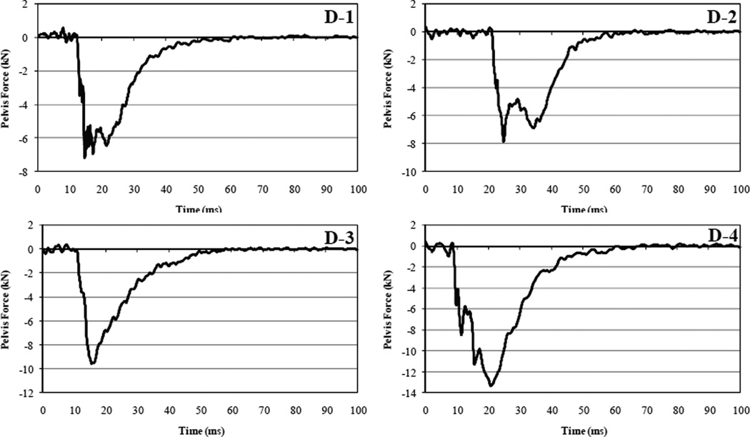
Peak signals and time of attainment are shown for the dynamic close-proximity airbag (Table 3) and the stationary airbag (Table 4) tests. Signal plots are included in the Appendix. For each test t = 0 represented airbag activation. Peak accelerometer signals were negative for tests S-2, S-4, and S-5 due to the right aspect loading. Peak T12 acceleration occurred as early as 2.0 ms following airbag activation; sequentially peak T12 accelerations occurred prior to T1 and sacrum peaks.
TABLE 3.
Signal peaks from accelerometers and load plates in dynamic tests.
| Test | T1 y (g) time (ms) |
T12 y (g) time (ms) |
Sac y (g) time (ms) |
Thorax force (N) time (ms) |
Abdomen force (N) time (ms) |
Pelvis Force (N) time (ms) |
|---|---|---|---|---|---|---|
| D-1 | 61.6 | 51.3 | 50.0 | −4547.1 | −2699.6 | −9184.7 |
| 22.7 | 12.7 | 18.6 | 5.3 | 14.2 | 14.8 | |
| D-2 | 36.5 | 34.8 | 61.3 | −5584.4 | −2254.7 | −7271.7 |
| 29.4 | 30.1 | 33.3 | 29.8 | 28.9 | 24.8 | |
| D-3 | 48.4 | 64.4 | 61.5 | −6310.4 | −2498.6 | −11640.0 |
| 28.7 | 11.0 | 17.1 | 20.7 | 17.4 | 15.5 | |
| D-4 | 37.6 | 60.3 | 82.2 | −7314.0 | −3185.2 | −10476.4 |
| 10.2 | 30.8 | 20.9 | 29.2 | 19.8 | 20.8 | |
TABLE 4.
Signal peaks from accelerometers in stationary tests
| Test | T1 y (g) time (ms) |
T12 y (g) time (ms) |
Sac y (g) time (ms) |
|---|---|---|---|
| S-1 | 4.1 | 19.4 | 3.8 |
| 6.7 | 6.1 | 12.2 | |
| S-2 | −34.3 | −22.6 | −4.0 |
| 12.9 | 11.8 | 20.3 | |
| S-3 | 10.7 | 26.4 | 3.2 |
| 15.2 | 4.6 | 13.6 | |
| S-4 | −7.9 | −25.0 | −3.1 |
| 13.2 | 2.0 | 12.3 | |
| S-5 | −34.7 | −19.1 | −2.8 |
| 15.6 | 2.5 | 13.8 | |
| S-6 | 8.4 | 31.9 | - |
| 15.6 | 2.1 | - | |
Chestband Analysis
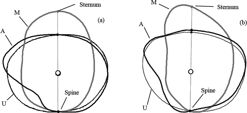
Shown in Figures 9 and 10 are exemplar chestband contours. For stationary tests (Fig. 9), contours are shown in undeformed and maximally deformed states. For dynamic tests (Fig. 10), contours are shown in undeformed states, intermediate states of posterolateral airbag interaction, and states of maximum total lateral deformation. Deformations initially occurred in the posterolateral region of the thorax and abdomen due to airbag interaction in similar manners for both stationary and dynamic test results. With dynamic impact progression, the airbag expanded between the thorax and load wall until inflator gases were fully exhausted. Following gas exhaustion, wall contact governed the chest deformation in the lateral region through deflated airbag fabric.
FIGURE 9.
Chest contours from stationary airbag test demonstrating deformation pattern in posterolateral direction: (a) left aspect deployment (S-3) and (b) right aspect deployment (S-4).
FIGURE 10.
Chest contours from dynamic test (D-1) demonstrating deformation pattern progressing from undeformed (U) to posterolateral airbag interaction (A) to maximum lateral deformation (M): (a) xyphoid and (b) axilla chestbands.
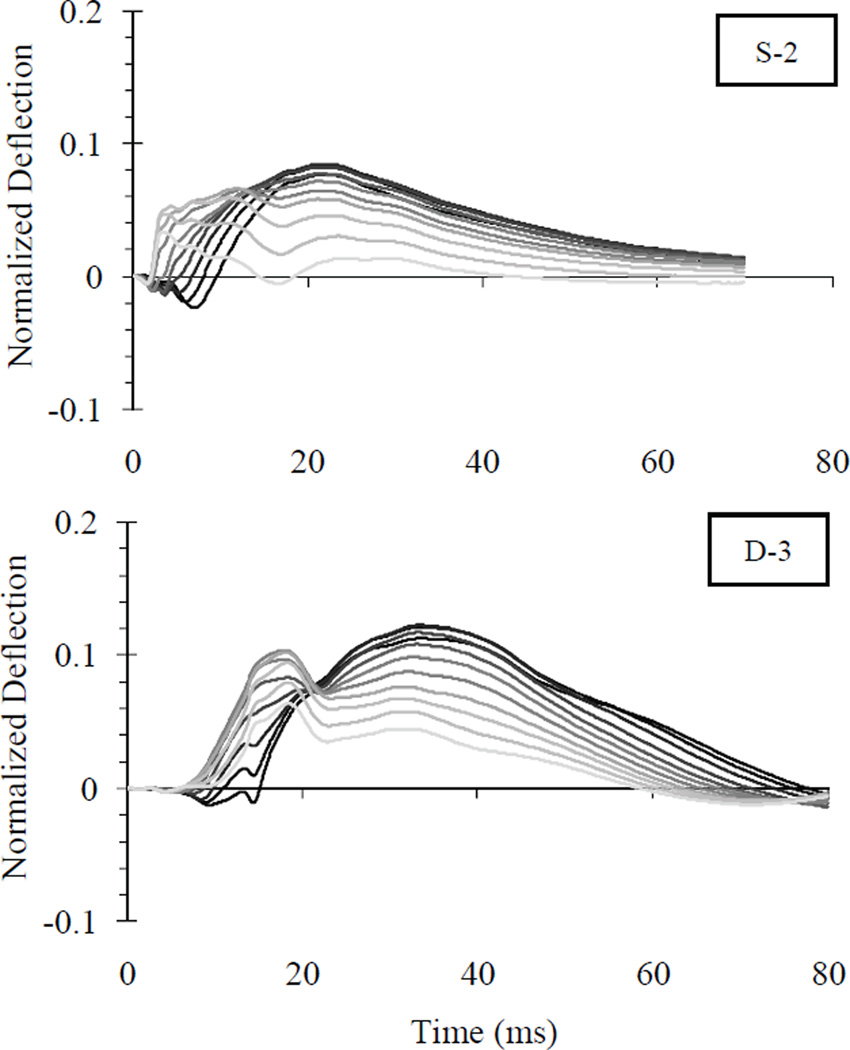
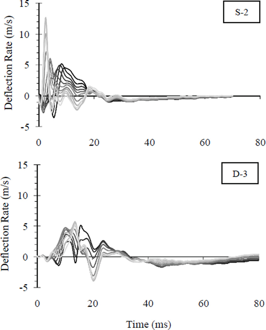
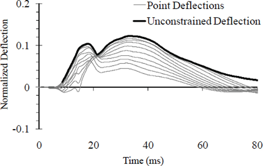
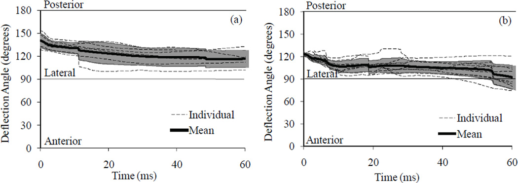
Normalized deflections were plotted along vectors between 90° and 140° (Fig. 11). Exemplar plots are shown in Figure 12; time zero was considered airbag activation. Deflections were characterized by two phases: initial contact (t < ~10 ms) and maximum deflection response (t > 10 ms). During initial contact, greater deflections were observed along oblique angles, i.e., θ > 110°, indicated by paler lines. Following initial contact with dynamic airbag interaction, deflections along lateral angles, i.e., θ < 110°, surpassed posterolateral deflection only with impact progression (t > 10 ms). Overall peak deflections were typically observed between 100° and 110° in sled impacts and between 115° and 135° in stationary tests. Airbag interaction was also characterized by high deflection rate (Fig. 13). With stationary interaction, peak rates were observed generally between 115° and 130°. With dynamic interaction, peak rates were observed between 90° and 135°; the greatest instance, 18.3 m/s was observed at 135°. Tables 5–7 contain peak normalized deflections, peak deflection rates, and VCmax for each chestband and angles in increments of 5°. To represent the transient locus of deformation response, a novel “unconstrained” deflection array was defined as the instantaneous peak deflection for each sample time (Fig. 14). The location of this instantaneous peak was defined by θ(t), which characterized the angle between the anterior direction and the transient deflection locus in time. Mean θ(t) response was determined for stationary airbag and dynamic airbag boundary conditions (Fig. 15). Time zero represented deformation onset, i.e., point at which measured deflection from at least one chestband first exceeded 4 mm. Angle of deformation onset was 141 ± 9° (mean ± SD) for contours from stationary tests and 122 ± 5° for contours from dynamic tests. Corridors are also depicted, which represent instantaneous average angle response for all contours ± 1 SD. Following initial airbag contact in stationary tests, deformation angle deviated toward 120° with respect to the S-S axis. Dynamic airbag contact induced deformations which deviated toward pure lateral, i.e., 90° with respect to S-S axis, with impact progression. Sixty milliseconds following deformation onset, the average angle was within 5° of a lateral deformation vector.
FIGURE 11.
Grayscale palate representing plotting of oblique deflection measurements.
FIGURE 12.
Exemplar normalized deflection traces for 90° through 140° vectors. Grayscale palate is depicted in Figure 11.
FIGURE 13.
Exemplar deflection rate traces for θ = 90° through 140° vectors. Grayscale palate is depicted in Figure 11.
TABLE 5.
Peak normalized deflection obtained from posterolateral oblique measurement vectors
| Test | Location | Vector Angle (°) | ||||||||||
|---|---|---|---|---|---|---|---|---|---|---|---|---|
| 140 | 135 | 130 | 125 | 120 | 115 | 110 | 105 | 100 | 95 | 90 | ||
| D-1 | Xyphoid | 0.121 | 0.136 | 0.153 | 0.165 | 0.176 | 0.187 | 0.196 | 0.199 | 0.200 | 0.197 | 0.188 |
| Axilla | 0.162 | 0.174 | 0.184 | 0.191 | 0.197 | 0.201 | 0.201 | 0.198 | 0.189 | 0.176 | 0.153 | |
| D-2 | Rib 10 | 0.093 | 0.112 | 0.129 | 0.143 | 0.159 | 0.174 | 0.185 | 0.192 | 0.194 | 0.193 | 0.186 |
| Xyphoid | 0.095 | 0.123 | 0.152 | 0.186 | 0.216 | 0.248 | 0.270 | 0.289 | 0.297 | 0.295 | 0.283 | |
| D-3 | Rib 10 | 0.064 | 0.080 | 0.094 | 0.102 | 0.104 | 0.099 | 0.108 | 0.117 | 0.123 | 0.121 | 0.113 |
| Xyphoid | 0.086 | 0.105 | 0.124 | 0.145 | 0.157 | 0.173 | 0.179 | 0.171 | 0.147 | 0.119 | 0.112 | |
| D-4 | Rib 10 | 0.086 | 0.106 | 0.114 | 0.115 | 0.113 | 0.114 | 0.111 | 0.104 | 0.094 | 0.083 | 0.069 |
| Xyphoid | 0.095 | 0.114 | 0.128 | 0.140 | 0.150 | 0.160 | 0.166 | 0.167 | 0.158 | 0.142 | 0.123 | |
| S-1 | Xyphoid | 0.117 | 0.119 | 0.117 | 0.110 | 0.100 | 0.084 | 0.062 | 0.035 | 0.023 | 0.019 | 0.015 |
| S-2 | Xyphoid | 0.033 | 0.047 | 0.059 | 0.066 | 0.065 | 0.072 | 0.077 | 0.0.82 | 0.085 | 0.083 | 0.077 |
| S-3 | Xyphoid | 0.132 | 0.142 | 0.143 | 0.136 | 0.121 | 0.107 | 0.091 | 0.075 | 0.057 | 0.037 | 0.021 |
| S-4 | Xyphoid | 0.089 | 0.103 | 0.111 | 0.109 | 0.097 | 0.077 | 0.054 | 0.028 | 0.026 | 0.021 | 0.016 |
| S-5 | Xyphoid | 0.051 | 0.059 | 0.067 | 0.072 | 0.075 | 0.075 | 0.074 | 0.073 | 0.070 | 0.065 | 0.057 |
| S-6 | Xyphoid | 0.149 | 0.163 | 0.170 | 0.170 | 0.162 | 0.147 | 0.126 | 0.104 | 0.078 | 0.051 | 0.028 |
TABLE 7.
Peak viscous response (m/s) obtained from posterolateral oblique measurement vectors
| Test | Location | Vector Angle (°) | ||||||||||
|---|---|---|---|---|---|---|---|---|---|---|---|---|
| 140 | 135 | 130 | 125 | 120 | 115 | 110 | 105 | 100 | 95 | 90 | ||
| D-1 | Xyphoid | 0.54 | 0.62 | 0.65 | 0.62 | 0.53 | 0.59 | 0.75 | 0.86 | 0.87 | 0.81 | 0.71 |
| Axilla | 0.59 | 0.57 | 0.53 | 0.49 | 0.45 | 0.40 | 0.39 | 0.42 | 0.40 | 0.34 | 0.31 | |
| D-2 | Rib 10 | 0.28 | 0.32 | 0.37 | 0.41 | 0.45 | 0.49 | 0.49 | 0.48 | 0.47 | 0.46 | 0.44 |
| Xyphoid | 0.29 | 0.55 | 0.87 | 1.28 | 1.71 | 2.22 | 2.64 | 3.02 | 3.22 | 3.20 | 2.96 | |
| D-3 | Rib 10 | 0.20 | 0.29 | 0.38 | 0.42 | 0.41 | 0.34 | 0.23 | 0.21 | 0.24 | 0.23 | 0.20 |
| Xyphoid | 0.24 | 0.32 | 0.42 | 0.49 | 0.58 | 0.65 | 0.64 | 0.54 | 0.54 | 0.46 | 0.28 | |
| D-4 | Rib 10 | 0.34 | 0.48 | 0.53 | 0.51 | 0.48 | 0.44 | 0.40 | 0.36 | 0.33 | 0.30 | 0.24 |
| Xyphoid | 0.35 | 0.44 | 0.47 | 0.51 | 0.50 | 0.66 | 0.96 | 1.26 | 1.41 | 1.33 | 1.07 | |
| S-1 | Xyphoid | 0.49 | 0.55 | 0.60 | 0.63 | 0.61 | 0.44 | 0.21 | 0.06 | 0.02 | 0.02 | 0.03 |
| S-2 | Xyphoid | 0.21 | 0.39 | 0.44 | 0.28 | 0.14 | 0.11 | 0.11 | 0.13 | 0.14 | 0.14 | 0.15 |
| S-3 | Xyphoid | 0.31 | 0.31 | 0.34 | 0.34 | 0.31 | 0.25 | 0.18 | 0.11 | 0.06 | 0.06 | 0.09 |
| S-4 | Xyphoid | 0.25 | 0.34 | 0.40 | 0.39 | 0.33 | 0.22 | 0.12 | 0.04 | 0.02 | 0.02 | 0.05 |
| S-5 | Xyphoid | 0.05 | 0.07 | 0.10 | 0.12 | 0.13 | 0.13 | 0.10 | 0.08 | 0.07 | 0.07 | 0.08 |
| S-6 | Xyphoid | 0.49 | 0.56 | 0.59 | 0.60 | 0.56 | 0.48 | 0.38 | 0.27 | 0.16 | 0.06 | 0.03 |
FIGURE 14.
Exemplar unconstrained deflection plotted with deflections at θ = 90° through 140°.
FIGURE 15.
Angle of deflection (θ) for stationary (a) and dynamic late deployment (b) airbag interaction. Shading denotes ± SD corridor.
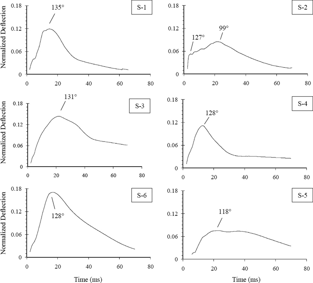
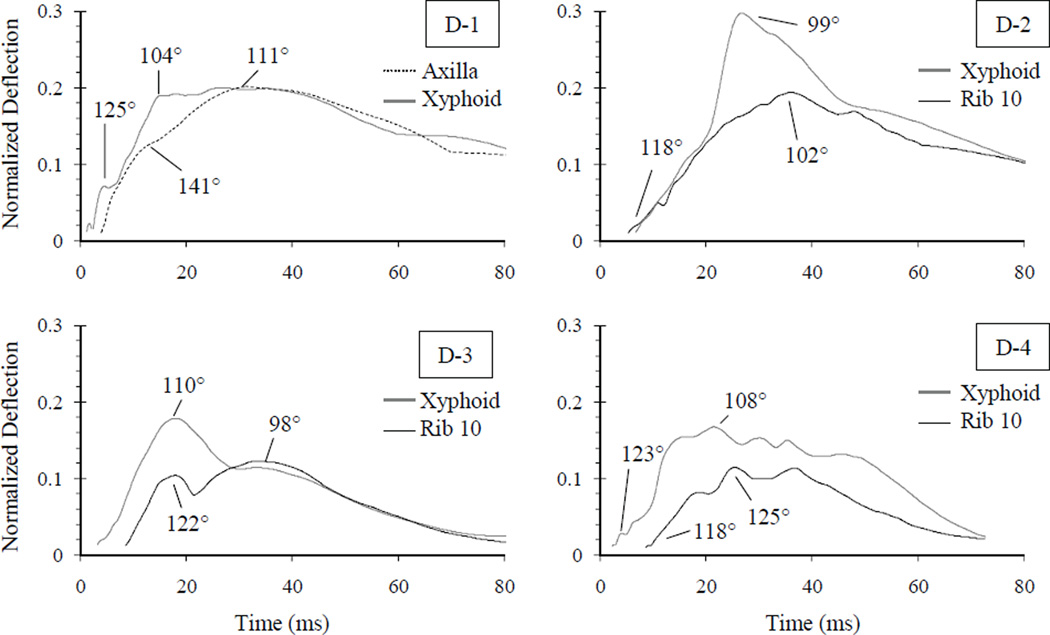
Measuring unconstrained deflection along θ(t), a single normalized deflection time trace was assembled representing overall contour deformation behavior. Unconstrained deflections are shown in Figures 16 and 17 for all chestbands. For dynamic tests in which two chestbands were utilized, results from identical tests are plotted on the same axes. Examining stationary tests, deformation onset, i.e., > 4 mm, ranged 1.9 – 5.8 ms following airbag activation (t = 0). Peak normalized deflections ranged 0.075 – 0.171 and occurred between θ = 99° and 135°. Test S-5, which demonstrated the least absolute deflection, initiated deformation 5.8 ms following airbag activation. This delay was longer than other tests, which ranged 1.9 – 2.4 ms. For dynamic airbag interaction (Fig. 17), contour deformation onset ranged 1.2 – 5.4 ms following airbag activation. Normalized deflections peaked between 0.167 – 0.297 at angles ranging θ = 98° to 125°.
FIGURE 16.
Unconstrained deflection time traces for stationary airbag interaction. Left-aspect response is depicted on left; right-aspect response is depicted on right. Angle (°) at which peaks occurred is indicated by arrow.
FIGURE 17.
Unconstrained deflection time traces from chestbands for dynamic close-proximity airbag interaction. Angle (°) at which peaks occurred is indicated.
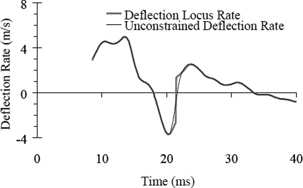
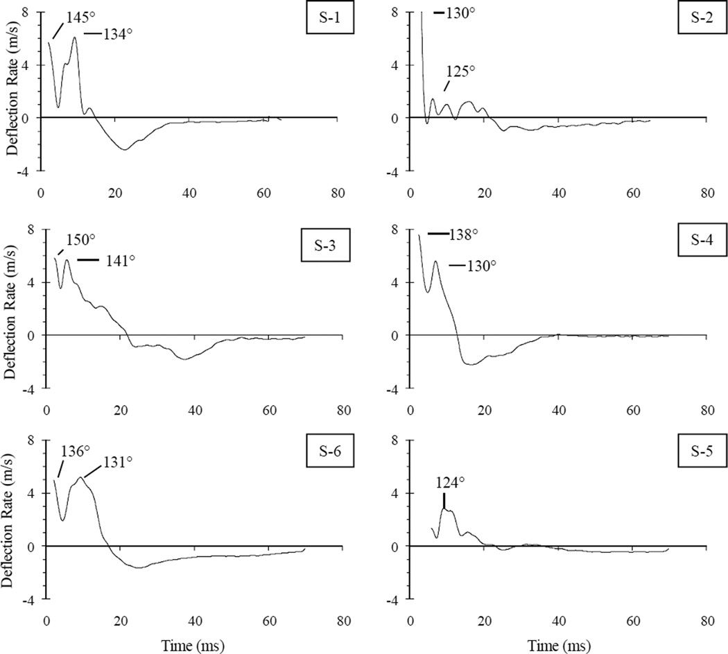
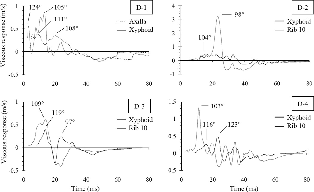
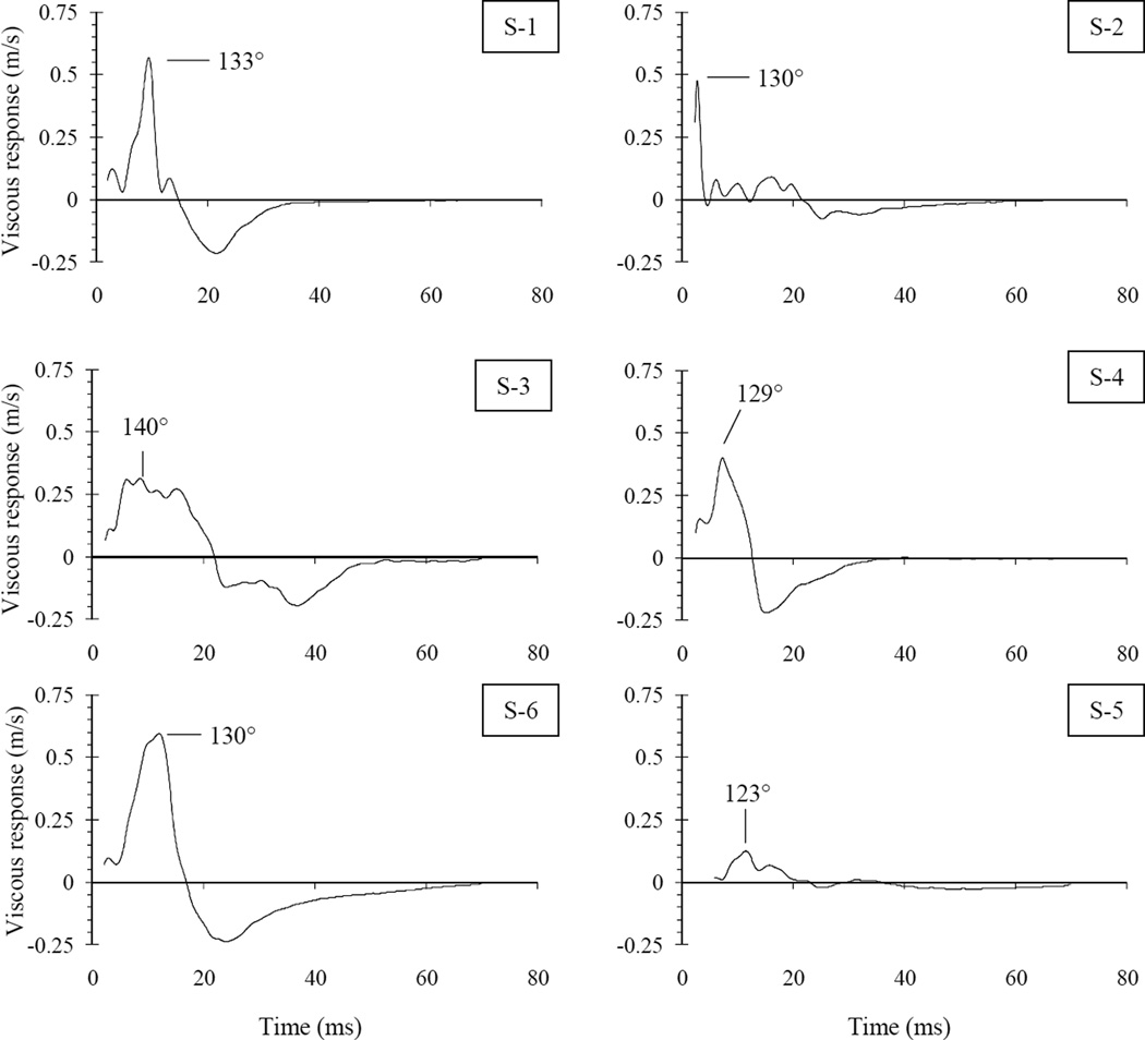
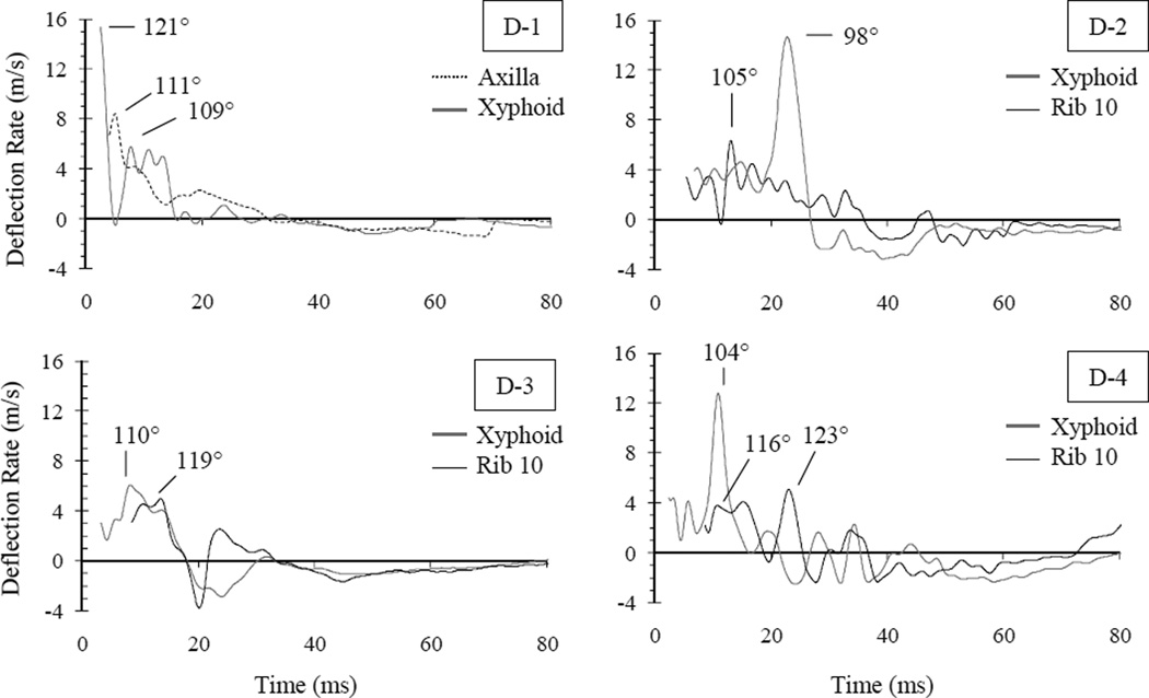
Rate response was quantified from unconstrained deflection by differentiation in time. Because the deflection locus was transient, these values may not represent the actual deflection rate of specific contour points. Therefore, rate of unconstrained deflection was compared in time to the instantaneous deflection rate of the point corresponding to the deflection locus. As demonstrated in Figure 18, rate obtained from differentiating the unconstrained deflection trace represented a good estimate of the instantaneous rate of deflection as measured at the deflection locus. Unconstrained deflection rate and viscous response are depicted in Figures 19–22 for all chestbands. Peak deformation rates ranged 5.0 – 15.4 m/s (Figs. 19–20). Peak deflection, peak deflection rate, and VCmax are shown for each chestband in Table 8. Time of attainment and angle of attainment are also listed. The highest rates by this method (D-1 and S-2) were observed at θ = 121° and 130°, respectively, and were attained at the xyphoid level chestband. Peak viscous responses ranged 0.62 – 3.23 m/s and occurred at θ = 98° – 109°. The highest VCmax (D-2) was observed at θ = 99° at the xyphoid level.
FIGURE 18.
Unconstrained deflection rate and the instantaneous rate of deflection measured at the deflection locus.
FIGURE 19.
Deflection rate traces for stationary airbag interaction. Left-aspect response is depicted on left; right-aspect response is depicted on right. Angle (θ) at which peaks occurred is indicated.
FIGURE 22.
Viscous response traces for dynamic close-proximity airbag interaction. Angle (θ) at which peaks occurred is indicated.
FIGURE 20.
Viscous response traces for stationary airbag interaction. Left-aspect response is depicted on left; right-aspect response is depicted on right. Angle (θ) at which peaks occurred is indicated.
TABLE 8.
Peak chestband metrics, time of attainment, and angle of attainment.
| Deflection | Deflection Rate | Viscous Response | ||||||||
|---|---|---|---|---|---|---|---|---|---|---|
| Test ID | Location | Peak | Time | Angle | Peak | Time | Angle | Peak | Time | Angle |
| (ms) | (degrees) | (m/s) | (ms) | (degrees) | (m/s) | (ms) | (degrees) | |||
| S-1 | Xyphoid | 0.119 | 14.6 | 135 | 6.1 | 9.1 | 134 | 0.57 | 9.4 | 133 |
| S-2 | Xyphoid | 0.085 | 21.4 | 99 | 16.9 | 2.4 | 130 | 0.48 | 2.8 | 130 |
| S-3 | Xyphoid | 0.144 | 22.0 | 132 | 5.8 | 2.3 | 151 | 0.31 | 8.6 | 140 |
| S-4 | Xyphoid | 0.111 | 12.8 | 128 | 7.6 | 2.4 | 138 | 0.40 | 7.3 | 129 |
| S-5 | Xyphoid | 0.075 | 23.2 | 116 | 2.9 | 9.2 | 124 | 0.12 | 11.6 | 123 |
| S-6 | Xyphoid | 0.171 | 16.9 | 128 | 5.2 | 9.2 | 131 | 0.59 | 12.0 | 130 |
| D-1 | Axilla | 0.201 | 31.2 | 112 | 8.4 | 5.0 | 115 | 0.38 | 9.2 | 111 |
| Xyphoid | 0.200 | 27.3 | 103 | 15.4 | 2.5 | 121 | 0.86 | 13.4 | 105 | |
| D-2 | Xyphoid | 0.297 | 26.7 | 99 | 14.7 | 22.8 | 98 | 3.23 | 23.4 | 98 |
| Rib 10 | 0.194 | 36.0 | 102 | 6.3 | 13.1 | 105 | 0.45 | 22.6 | 94 | |
| D-3 | Xyphoid | 0.179 | 18.1 | 110 | 6.1 | 8.3 | 110 | 0.62 | 14.1 | 109 |
| Rib 10 | 0.123 | 33.4 | 98 | 5.0 | 13.6 | 119 | 0.40 | 13.9 | 119 | |
| D-4 | Xyphoid | 0.167 | 21.5 | 108 | 12.8 | 10.9 | 104 | 1.32 | 11.3 | 103 |
| Rib 10 | 0.115 | 25.4 | 125 | 5.1 | 23.0 | 123 | 0.50 | 23.3 | 123 | |
DISCUSSION
The purpose of this study was to describe biomechanical and injury responses to posterolateral interaction with side airbag, with and without sled ΔV. In previous experimental designs, thoracic loading direction was controlled by test setup. Oblique direction was controlled via specimen orientation with respect to the impactor motion (Chung et al., 1999; Nusholtz et al., 1983; Shaw et al., 2006; Viano et al., 1989b; Yoganandan et al., 1997) or boundary orientation with respect to the subject motion (Pintar et al., 2007; Yoganandan et al., 2007; Yoganandan et al., 2008). In this study, direction was not controlled directly by the experimental design. Because deformation was initiated by airbag deployment, the direction was influenced by airbag-subject interaction resulting primarily from independent airbag deployment characteristics. This boundary condition represents a realistic posterolateral loading modality in vehicular environments because variations in lateral positions of vehicular occupants as large as 22 cm have been reported (Dinas and Fildes, 2002).
Biomechanical response was influenced by variations in localized airbag deployment characteristics. Care was taken to ensure that subjects were positioned in a precise repeatable manner. Yet, stationary tests S-2 and S-5 were marked by reductions in peak biomechanical response, particularly normalized deflection and spinal acceleration (Fig. 16 and Table 4). In these tests, it was apparent that airbag deployment escaped inferiorly, which reduced torso loading compared to the contralateral tests which utilized the same specimen (S-1 and S-6). In the case of S-5, this reduced response was also marked by an approximate 2 ms delay in deformation onset compared to the other tests. This suggests that this subject was the farthest from the airbag in this test series. Other stationary side airbag studies have made similar observations regarding positioning and response variability. With child ATDs, it was noted that a 75% reduction in biomechanical response resulted from 2 cm position deviations (Pintar et al., 1999). Dynamic tests also demonstrated variability. Although airbags during the dynamic impacts were triggered at similar instants, deployment progression results (Fig. 7) and subsequent peak biomechanical responses (Tables 5–7 and Fig. 17) were diverse. Test D-2 demonstrated the greatest amount of forward airbag expansion, which may have resulted in the highest normalized deflection at the xyphoid level. Test D-1, which also exhibited a degree of forward expansion greater than D-3 and D-4, experienced the highest deformation rate and the most severe skeletal and visceral injury. These injuries are further elaborated in following sections.
Biomechanical Response
Biomechanical responses were compared to other boundary conditions from previously reported sled tests to provide a baseline comparison. These tests utilized an identical side impact sled device and ΔV = 6.7 m/s but boundary conditions represented either flat or anterolateral oblique rigid wall (Kuppa et al., 2003; Maltese et al., 2002; Pintar et al., 1997; Yoganandan et al., 2007; Yoganandan et al., 2008). Two flat rigid tests were selected to validate the novel RBandPC methodology utilized for this study, in which the spine and sternum locations were translated contralaterally by 10% (Fig. 3). This methodology was compared to “traditional” RBandPC analyses in which the anatomical spine and sternum locations were maintained. Peak differences in biomechanical response are shown in Table 9; peak normalized deflection deviated by less than 1%, while VCmax deviated by a maximum of 4.0%.
TABLE 9.
Maximum error observed in altered RBandPC analysis
| Test ID | SC120 | SC121 | |
|---|---|---|---|
| Peak ΔNormD | - | 0.0008 | 0.0006 |
| eNormD | (%) | 0.39 | 0.29 |
| Peak ΔV | (m/s) | 0.658 | 0.155 |
| eV | (%) | 9.3 | 2.3 |
| ΔVCmax | (m/s) | 0.029 | 0.016 |
| eVCmax | (%) | 4 | 2.7 |
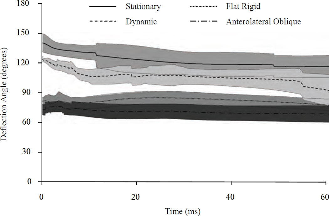
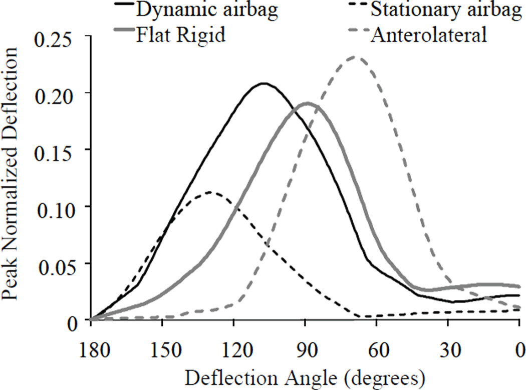
In dynamic tests with the airbag, overall peak metrics were observed consistently at the xyphoid level chestband (T11 level posteriorly), corresponding to the site of maximum airbag interaction (Tables 5–7). Thus biomechanical response at this level was compared to the baseline boundary conditions. Depicted in Figure 23 is mean deflection angle response θ(t) for stationary and dynamic airbag interaction as well as flat rigid and anterolateral oblique boundary conditions. At deflection onset, mean deflection angle resulting from dynamic airbag interaction was 35° greater (Student’s t-test; p < 0.001) than flat or anterolateral oblique contact. Further, both stationary and dynamic airbag interaction demonstrated transient deflection loci varying 20° and 30° over the first 60 ms of impact, respectively; deflection angles resulting from flat and anterolateral rigid interaction did not vary more than 5°. Depicted in Figure 24 is the peak normalized deflection at the xyphoid level represented as a function of obliquity (θ). Response was averaged for each boundary condition. As shown, stationary airbag tests induced minimal deflection at θ = 90° compared to other boundary conditions, but deflection magnitude was similar to dynamic airbag interaction when approximately θ ≥ 130°. Mean deflection from dynamic airbag tests at θ = 90° was reduced compared to flat rigid wall and approximately equal to the anterolateral boundary condition. Peak deflections with airbag interaction did not occur at θ = 90° and, considering the overall peaks, posterolateral airbag interaction increased deflection compared to flat rigid wall (Fig. 24). However, because of the oblique direction the relationship to injury risk is unclear. Peak average deflection occurred at θ = 130° and 108° for stationary and dynamic airbag interaction, respectively. As expected, average peak deflection response to flat and anterolateral rigid boundary occurred at lateral and anterolateral angles.
FIGURE 23.
Angle of deflection (in degrees) for stationary airbag, dynamic airbag, flat rigid wall and oblique load wall configurations. Shading denotes ± SD corridors.
FIGURE 24.
Angle of deflection (in degrees) for stationary airbag, dynamic airbag, flat rigid wall and oblique load wall configurations. Shading denotes ± SD corridors.
Injury
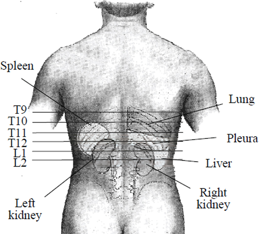
Four PMHS were subjected to sled tests at ΔV = 6.7 m/s utilizing “ideally” inflated torso airbags, i.e., sufficient deployment time to attain full volume with no posterolateral contact (Kuppa et al., 2003). These test specimens demonstrated ≤ 3 rib fractures each, with two PMHS sustaining no injury. Previous stationary tests of torso side airbags have resulted in posterolateral fractures to ribs 8 – 10 (Duma et al., 1998). While injuries induced by sled impacts with close-proximity airbags were more severe than the ideal boundary condition, rib fractures from the stationary tests were similar to the literature. Yet, apparently unique visceral trauma was observed in this study. One stationary test and three dynamic tests were characterized by lacerations to kidney or, particularly, the spleen. During necropsy, the dynamic test subject without visceral trauma was found to have undergone a perimortem splenectomy. Visceral lacerations ran in both cranial-caudal and medial-lateral (transverse) directions. The cranial-caudal lacerations may have resulted from shearing induced by overlying rib fracture displacement. The spleen, deep to the posterolateral curvature of ribs 9 – 11 and posterior to the mid-axillary line (Bergman et al., 2002), may be particularly sensitive to rib fractures in this region (Fig. 25). This injury mechanism appeared most likely in test S-6, where an overlying fracture to the ninth rib was displaced medially. Similarly, two of the three splenic lacerations observed in D-1 demonstrated a cranial-caudal orientation indicative of rib fracture interaction. Yet, in all tests the lack of observed trauma to the diaphragm, which separates the spleen from the chest wall, suggests that direct interaction with fractured ribs may be less likely.
FIGURE 25.
Posterior view of gross visceral anatomy in external context. Modified from Gray (1918).
The number of fractured ribs observed in dynamic tests appeared consistent with other boundary conditions utilizing this sled geometry. PMHS subjected to flat rigid boundary conditions have sustained varying severity of injury ranging from no rib fractures (AIS 0) to greater than ten rib fractures (MAIS 4) with possible flail chest (Kuppa et al., 2003; Pintar et al., 1997). Subjected to anterolateral loading, PMHS sustained between 4 and 7 fractured ribs (Yoganandan et al., 2008). Yet, kidney or spleen trauma was not reported except in PMHS subjected to a higher impact velocity (ΔV = 8.9 m/s) or to thoracic or abdominal load wall offsets (Kuppa et al., 2003; Pintar et al., 1997). With anterolateral oblique load wall, lung contusion was reported in one test but trauma to the spleen or kidneys was not observed. The absence of underlying visceral trauma reported by Kuppa et al. and Pintar et al. suggests that, in the present study, the visceral injury mechanism may be more complex than rib fracture interaction. The capsular tears to the posterior ends of the spleen observed in D-4 and in D-1, and to the kidney observed in D-2 were not located in the vicinity of any rib fractures. These lacerations were oriented in a medial-lateral (transverse) direction in D-1 and D-2 and may have resulted from some other failure mechanism. This mechanism cannot be ruled out in test S-6 or in other lacerations observed in D-1. From the literature, trauma to these underlying posterolateral viscera appears rare at this test ΔV. Of more than 70 tests performed at or below ΔV = 8.0 m/s, only one cadaveric test is known to the authors in which splenic trauma was reported (Cavanaugh et al., 1996); none were reported with identical sled geometry (Cavanaugh et al., 1993; Cavanaugh et al., 1996; Eppinger et al., 1984; Kallieris et al., 1981; Kuppa et al., 2003; Marcus et al., 1983; Melvin et al., 1976; Morgan and Waters, 1980; Pintar et al., 1997; Viano et al., 1989b). Liver trauma was not observed despite greater prevalence in the aforementioned studies, but right aspect sled loading with close-proximity airbag was not examined. Because of spleen, liver, and kidney locations in situ (Fig. 25), previous studies have observed the susceptibility of these organs to localized deformation patterns (Cavanaugh et al., 1996; Gray, 1918; Kuppa et al., 2003; Rouhana and Kroell, 1989). The upper abdominal locations of these viscera are consistent with the regions of deformation observed in this study. Because few injuries have been attributed to side airbag deployment (Dalmotas et al., 2001; Hallman et al., 2009; Kirk and Morris, 2003), the exact incidence of posterolateral side airbag loading remains unknown. Yet the increasing popularity of side airbags affirms that current injury criteria should be validated with a posterolateral loading modality.
Injury Metrics
Because posterolateral deformations appeared to induce soft tissue injury with greater frequency than flat lateral and anterolateral loading in PMHS sled tests, a relationship between visceral trauma and posterolateral biomechanics is suspected. Although this relationship would require more than the ten side airbag tests conducted to conclusively establish, a rudimentary analysis was performed to identify biomechanical response measurements which may correlate with these injuries. Such measurements should be applicable to both stationary and dynamic airbag loading if injuries occurring in these scenarios resulted from the same mechanism. For this reason, all deflections were normalized to chest breadth. Yet, increased obliquity in stationary test results may suggest that deflections could also be normalized to chest depth.
Normalized deflection response from four boundary conditions (Fig. 24) was analyzed using ANOVA to identify regions of statistical dissimilarity. Normalized deflections differed significantly (α = 0.05) between all boundary conditions. Fisher’s post-hoc test compared biomechanical response between both side airbag boundary conditions, and identified that dynamic and stationary airbag interactions were not significantly different when θ ≥ 130°.
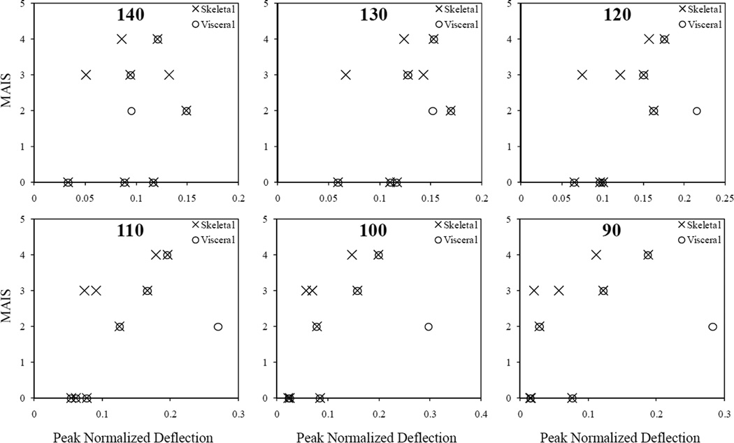
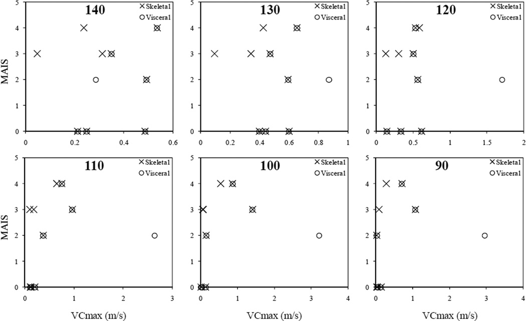
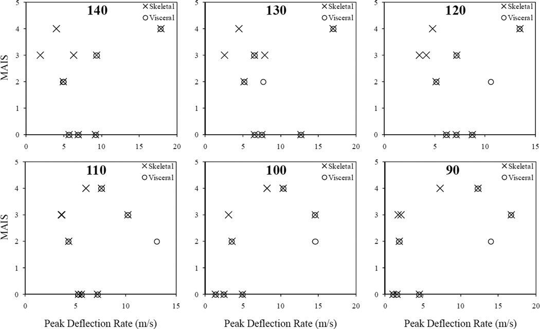
Maximum thoracoabdominal AIS were plotted against biomechanical responses measured along oblique angles for the two side airbag boundary conditions (Figs. 26–28). Responses along constrained angles of θ = 90° – 140° were plotted separately so that equivalent biomechanical parameters were compared. To highlight skeletal and visceral injuries, separate markers represent the presence of either in each test specimen. Although no statistical evaluation was conducted, a generally positive relationship was observed between peak normalized deflection and skeletal injury (Fig. 26). Previous work has correlated normalized chest deflection with rib fracture in lateral impact (Cavanaugh et al., 1993; Kuppa et al., 2003; Pintar et al., 1997; Rouhana et al., 1985; Viano et al., 1989b). Yet, in this study the relationship appeared stronger for between θ = 100° and 120°, suggesting that oblique deflections are important in these boundary conditions. Examining the relationship between peak deflection rate and injury (Fig. 27), Vmax ≥ 10 m/s appeared to induce injury consistently; a similar threshold value was reported in rabbit subjects (Rouhana et al., 1985). Plotted against VCmax (Fig. 28), injuries appeared to correlate best for θ = 120° and 130°. At these angles VCmax ≥ 0.5 m/s was associated with visceral injury but not skeletal injury. For θ = 90° – 110°, VCmax measurements were near-zero for at least one injured subject, suggesting that this measurement direction may not be appropriate Previous work has noted weaker skeletal injury correlations to VCmax compared to visceral injury (Kuppa et al., 2003; Lau and Viano, 1986; Viano et al., 1989a; Viano et al., 1989b). Because visceral injuries noted in the present study have not been typically observed at this ΔV heretofore, viscous response at posterolateral angles may be causally related to localized visceral injury (Lau and Viano, 1986; Lau and Viano, 1981; Rouhana et al., 1985; Viano and Lau, 1983). Yet due to deflection loci transience in dynamic airbag tests (Fig. 15), this angle may not represent the overall maximum response calculated on the chestband and thus would not replace lateral metrics.
FIGURE 26.
Peak normalized deflection and corresponding maximum thoracoabdominal AIS for deflection angles 140°, 130°, 120°, 110°, 100°, and 90°.
FIGURE 28.
Peak viscous response and corresponding maximum thoracoabdominal AIS for deflection angles 140°, 130°, 120°, 110°, 100°, and 90°.
FIGURE 27.
Peak deflection rate and corresponding maximum thoracoabdominal AIS for deflection angles 140°, 130°, 120°, 110°, 100°, and 90°.
LIMITATIONS
This study represents the first step in a process necessary to understand posterolateral loading to the torso utilizing PMHS. As such, the limitations of this laboratory-based study should be considered when interpreting these results. Because PMHS in stationary tests were subjected to two impacts, visceral injury could have been induced during specimen manipulation if rib fractures were present. However, S-6 was conducted following S-5, and thus contralateral splenic injury during right side airbag deployment could be excluded in this case.
Visceral trauma is reportedly less frequent and less severe in cadaveric specimens compared to in vivo experiments at similar impact severities (Nusholtz et al., 1980; Rouhana, 1993; Yoganandan et al., 2001). Thus, soft tissue injury observations in this study should be confirmed by in vivo studies utilizing live surrogates such as porcine models or viscoelastic computational methods. These methods would also be necessary for the development of injury criteria from this loading modality.
The absence of vehicle-specific seat and door trim pieces may affect the direct correlation between this airbag boundary condition and real world crashes, as these have been shown to affect biomechanical response (Horsch et al., 1990; Melvin et al., 1993; Mertz et al., 1982). Similarly, no tests were conducted without chestbands in place. The highly fluid nature of airbag deployment suggests that the chestband may affect biomechanical or injury response during close-proximity airbag interaction. The chestband may reduce punch-out effects by distributing forces over a larger area or increase membrane effects by introducing focal loads to the underlying anatomy. While previous chestband studies have not observed localized chestband effects (Morgan et al., 1994; Pintar et al., 1997; Shaw et al., 2006), further consideration is warranted.
Impacts were performed in a Heidelberg-type sled with constant door ΔV. Although this device has been suggested to under-represent the loading subjected to the thorax in the lateral impact environment (Kent et al., 2001; Morris et al., 1999), prior studies have correlated injury and injury metrics between this sled environment and full-scale vehicle crashes (Cavanaugh et al., 1993; Pintar et al., 1997) and shown door parameters to govern occupant response (Dargaud and Bourdillon, 1986; Watson et al., 2009). Yet, the complexity of lateral motor vehicle crashes complicates the direct application of this study to real world crashes with side airbags.
SUMMARY AND CONCLUSION
Ten PMHS tests were conducted to observe the biomechanical and injury response to posterolateral interaction with a deploying torso side airbag. A novel chestband analysis methodology was developed for directional analysis of thoracoabdominal deformation. With sled ΔV, the side airbag boundary condition induced chest deflections along an angle between 120° and 90° with respect to the mid-sagittal plane. Resulting peak normalized deflection, peak deflection rate, and VCmax ranged 0.167 – 0.297, 7.4 – 18.3 m/s, and 0.7 – 3.0 m/s, respectively. Stationary airbag interaction induced deflections between 141° and 120°. With this boundary condition, resulting peak normalized deflection, peak deflection rate, and VCmax ranged 0.075 – 0.171, 3.7 – 12.7 m/s, and 0.3 – 0.6 m/s, respectively. Transient deformation response suggests that use of global peak metrics or singular measurement locations may omit biomechanical response resulting from initial airbag contact. Therefore, biomechanical response measurement of posterolateral side airbag interaction with anthropomorphic test devices may require localized instrumentation such as those possible with multipoint tracking systems or obliquely mounted sensors. These initial results indicated that a transducer 130° with respect to the forward mid-sagittal plane would be appropriate.
FIGURE 21.
Deflection rate traces for dynamic close-proximity airbag interaction. Angle at which peaks occurred is indicated.
TABLE 6.
Peak deflection rates (m/s) obtained from posterolateral oblique measurement vectors
| Test | Location | Vector Angle (°) | ||||||||||
|---|---|---|---|---|---|---|---|---|---|---|---|---|
| 140 | 135 | 130 | 125 | 120 | 115 | 110 | 105 | 100 | 95 | 90 | ||
| D-1 | Xyphoid | 17.8 | 18.3 | 17.0 | 15.3 | 13.4 | 10.7 | 7.6 | 8.7 | 10.4 | 11.7 | 12.3 |
| Axilla | 5.0 | 4.5 | 3.9 | 5.0 | 6.8 | 8.4 | 9.5 | 10.0 | 9.2 | 6.8 | 5.6 | |
| D-2 | Rib 10 | 5.5 | 5.0 | 4.6 | 4.4 | 4.7 | 5.2 | 5.8 | 6.3 | 6.9 | 7.3 | 7.6 |
| Xyphoid | 5.0 | 6.3 | 7.7 | 9.3 | 10.6 | 12.0 | 13.1 | 14.1 | 14.6 | 14.6 | 14.1 | |
| D-3 | Rib 10 | 5.2 | 5.6 | 5.7 | 5.6 | 5.1 | 4.7 | 4.7 | 4.4 | 3.7 | 5.1 | 7.4 |
| Xyphoid | 4.0 | 4.2 | 4.5 | 4.7 | 4.8 | 5.1 | 6.1 | 7.3 | 8.2 | 8.1 | 7.3 | |
| D-4 | Rib 10 | 5.0 | 5.6 | 5.5 | 5.2 | 5.0 | 4.6 | 4.4 | 4.5 | 4.7 | 4.9 | 4.7 |
| Xyphoid | 9.3 | 8.3 | 6.5 | 6.7 | 7.2 | 7.8 | 10.2 | 12.6 | 14.6 | 16.0 | 16.7 | |
| S-1 | Xyphoid | 5.7 | 5.9 | 6.6 | 7.6 | 8.7 | 8.7 | 7.2 | 4.7 | 2.5 | 0.9 | 1.1 |
| S-2 | Xyphoid | 9.2 | 12.2 | 12.7 | 10.1 | 7.2 | 6.0 | 5.6 | 4.3 | 5.0 | 5.2 | 4.5 |
| S-3 | Xyphoid | 6.3 | 7.1 | 7.9 | 7.0 | 4.2 | 3.9 | 3.6 | 3.5 | 3.1 | 2.3 | 1.7 |
| S-4 | Xyphoid | 6.9 | 7.6 | 7.5 | 7.0 | 6.2 | 6.1 | 5.3 | 3.0 | 1.4 | 1.5 | 1.6 |
| S-5 | Xyphoid | 1.9 | 2.2 | 2.6 | 2.9 | 3.4 | 3.7 | 3.6 | 3.2 | 3.1 | 2.8 | 2.1 |
| S-6 | Xyphoid | 4.9 | 5.1 | 5.2 | 5.2 | 5.1 | 4.8 | 4.3 | 4.1 | 3.5 | 2.8 | 1.9 |
ACKNOWLEDGMENTS
This research was supported in part by the National Institutes of Health (R01AG024443), the National Science Foundation Graduate Research Fellowship Program, and Veterans Affairs Medical Research. The authors are grateful for the assistance of Mr. John Humm and Mr. Mark Meyer of the Neuroscience-Biomechanics Laboratories.
APPENDIX
FIGURE A.1. T1 y-axis accelerometer signals (CFC180). Tests S-2, S-4, and S-5 represent right-sided contact.
FIGURE A.2. T12 y-axis accelerometer signals (CFC180). Tests S-2, S-4, and S-5 represent right-sided contact.
Figure A.3. Sacrum y-axis accelerometer signals (CFC180). Tests S-2, S-4, and S-5 represent right-sided contact.
FIGURE A.4. Thorax force plate response (CFC600).
FIGURE A.5. Abdomen force plate response (CFC600).
FIGURE A.6. Pelvis force plate response (CFC600).
Footnotes
This research was reviewed and approved by the Institutional Review Board at the participating institutions.
REFERENCES
- AAAM. Abbreviated Injury Scale - 2005 Edition. Barrington, IL.: Association for the Advancement of Automotive Medicine; 2005. [Google Scholar]
- Automotive News. U.S. Car Sales by Nameplate. 2008 [Google Scholar]
- Bergman RA, Heidger PM, Scott-Conner CEH. The Anatomy of the Spleen. USA: Humana Press; 2002. pp. 3–10. [Google Scholar]
- Cavanaugh JM, Wililko T, Chung J, King AI. Proc. 40th Stapp Car Crash Conference. Warrendale, PA.: Society of Automotive Engineers; 1996. Abdominal injury and response in side impact; pp. 1–16. [Google Scholar]
- Cavanaugh JM, Zhu Y, Huang Y, King AI. Proc. 37th Stapp Car Crash Conference. Warrendale, PA.: Society of Automotive Engineers; 1993. Injury and response of the thorax in side impact cadaveric tests; pp. 199–221. [Google Scholar]
- Chung J, Cavanaugh JM, King AI, Koh S, Deng YC. Thoracic injury mechanisms and biomechanical responses in lateral velocity pulse impacts. Proc. 43rd Stapp Car Crash Conference, Society of Automotive Engineers; Warrendale, PA.. 1999. [Google Scholar]
- Dalmotas D, German A, Tylko S. The crash and field performance of side-mounted airbag systems. Proc. 17th International Technical Conference on the Enhanced Safety of Vehicles, National Highway Traffic Safety Administration; Washington, DC.. 2001. [Google Scholar]
- Dargaud R, Bourdillon T. SAE 860051. Warrendale, PA.: Society of Automotive Engineers; 1986. Simulation of lateral impact with mobile deformable barrier; pp. 41–50. [Google Scholar]
- Dinas A, Fildes BN. Proc. 46th AAAM Conference. Barrington, IL.: Association for the Advancement of Automotive Medicine; 2002. Observations of seating position of front seat occupants relative to the side of the vehicle; pp. 27–43. [PubMed] [Google Scholar]
- Dischinger PC, Cushing BM, Kerns TJ. Injury patterns associated with direction of impact: drivers admitted to trauma centers. The Journal of Trauma. 1993;35(3):454–459. doi: 10.1097/00005373-199309000-00020. [DOI] [PubMed] [Google Scholar]
- Duma SM, Crandall JR, Hurwitz SR, Pilkey WD. SAE Trans. 983148. Warrendale, PA.: Society of Automotive Engineers; 1998. Small female upper extremity interaction with a deploying side air bag. [Google Scholar]
- Eppinger RH, Augustyn K, Robbins DH. Proc. 22nd Stapp Car Crash Conference. Warrendale, PA.: Society of Automotive Engineers; 1978. Development of a promising universal thoracic trauma prediction methodology; pp. 221–268. [Google Scholar]
- Eppinger RH, Marcus JH, Morgan RM. SAE 840885. Warrendale, PA.: Society of Automotive Engineers; 1984. Development of dummy and injury index for NHTSA's thoracic side impact protection research program. [Google Scholar]
- Gray H. The Anatomy of the Human Body. Philadelphia: Lea & Febiger; 1918. [Google Scholar]
- Hallman JJ, Brasel KJ, Yoganandan N, Pintar FA. Splenic trauma as an adverse effect of torso-protecting side airbags: Biomechanical and case evidence. Annals of Advances in Automotive Medicine. 2009;53:13–24. [PMC free article] [PubMed] [Google Scholar]
- Hallman JJ, Yoganandan N, Pintar FA. Thoracic injury metrics with side airbag: Stationary and dynamic occupants. Traffic Injury Prevention. 2010;11(4):433–442. doi: 10.1080/15389581003753017. [DOI] [PMC free article] [PubMed] [Google Scholar]
- Hallman JJ, Yoganandan NA, Pintar FA. Characterization of torso side airbag aggressivity. Biomedical Sciences Instrumentation. 2009;45:101–106. [PMC free article] [PubMed] [Google Scholar]
- Horsch JD, Lau IV, Andrzejak DV, Viano DC, Melvin JW, Pearson J, Cok D, Miller G. Proc. 34th Stapp Car Crash Conference. Warrendale, PA.: Society of Automotive Engineers; 1990. Assessment of air bag deployment loads; pp. 267–288. [Google Scholar]
- IIHS. Vehicles equipped with side airbags. Insurance Institute for Highway Safety; 2009. [Google Scholar]
- Kallieris D, Mattern R, Schmidt G, Eppinger RH. Proc. 25th Stapp Car Crash Conference. Warrendale, PA.: Society of Automotive Engineers; 1981. Quantification of side impact responses and injuries; pp. 329–366. [Google Scholar]
- Kent R, Crandall J, Butcher J, Morris R. SAE Trans. 2001-0-0721. Warrendale, PA.: Society of Automotive Engineers; 2001. Sled system requirements for the analysis of side impact thoraic injury criteria and occupant protection. [Google Scholar]
- Kirk A, Morris A. Side airbag deployments in the UK - Initial case reviews. Proc. 18th International Technical Conference on the Enhanced Safety of Vehicles, National Highway Transportation Safety Administration; Washington, DC.. 2003. [Google Scholar]
- Kuppa S, Eppinger RH, McKoy F, Nguyen T, Pintar FA, Yoganandan N. Development of Side Impact Thoracic Injury Criteria and Their Application to the Modified ES-2 Dummy with Rib Extensions (ES-2re) Stapp Car Crash Journal. 2003;47:189–210. doi: 10.4271/2003-22-0010. [DOI] [PubMed] [Google Scholar]
- Lau IV, Viano DC. Proc. 30th Stapp Car Crash Conference. Warrendale, PA.: Society of Automotive Engineers; 1986. The viscous criterion - bases and applications of an injury severity index for soft tissues; pp. 123–142. [Google Scholar]
- Lau VK, Viano DC. Influence of impact velocity on the severity of nonpenetrating hepatic injury. The Journal of Trauma. 1981;21(2):115–123. doi: 10.1097/00005373-198102000-00004. [DOI] [PubMed] [Google Scholar]
- Maltese MR, Eppinger RH, Rhule HH, Donnelly BR, Pintar FA, Yoganandan N. Response corridors of human surrogates in lateral impacts. Stapp Car Crash Journal. 2002;46:321–351. doi: 10.4271/2002-22-0017. [DOI] [PubMed] [Google Scholar]
- Marcus JH, Morgan RM, Eppinger RH, Kallieris D, Mattern R, Schmidt G. Proc. 27th Stapp Car Crash Conference. Warrendale, PA.: Society of Automotive Engineers; 1983. Human response to and injury from lateral impact; pp. 419–432. [Google Scholar]
- Melvin JW, Horsch JD, McCleary JD, Wideman LC, Jensen JL, Wolanin MJ. Assessment of airbag deployment loads with the small female hybrid III dummy. Proc. 37th Stapp Car Crash Conference, Society of Automotive Engineers; Warrendale, PA.. 1993. [Google Scholar]
- Melvin JW, Robbins DH, Stalnaker RL. Proc. Sixth International Technical Conference on the Enhanced Safety of Vehicles. Washington, DC.: NHTSA; 1976. Side impact response and injury; pp. 681–689. [Google Scholar]
- Mertz HJ, Driscoll GD, Lenox JB, Nyquist GW, Weber DA. Proc. 9th International Technical Conference on the Enhanced Safety of Vehicles. Washington, DC.: National Highway Traffic Safety Administration; 1982. Responses of animals exposed to deployment of various passenger inflatable restraint system concepts for a variety of collision severities and animal positions; pp. 352–368. [Google Scholar]
- Morgan RM, Eppinger RH, Haffner MP, Yoganandan N, Pintar FA, Sances A, Crandall JR, Pilkey WD, Klopp GS, Kallieris D, Miltner E, Mattern R, Kuppa SM, Sharpless CL. Proc. 38th Stapp Car Crash Conference. Warrendale, PA.: Society of Automotive Engineers; 1994. Thoracic trauma assessment formulations for restrained drivers in simulated frontal impacts; pp. 15–34. [Google Scholar]
- Morgan RM, Waters HP. Proc. 8th International Technical Conference on the Experimental Safety of Vehicles. Washington, DC.: National Highway Traffic Safety Administration; 1980. Comparison of two promising side impact dummies; pp. 472–482. [Google Scholar]
- Morris RA, Crandall JR, Pilkey WD. Multibody modelling of a side impact test apparatus. International Journal of Crashworthiness. 1999;4(1):17–29. [Google Scholar]
- Nusholtz GS, Melvin JW, Mueller G, MacKenzie JR, Burney R. Proc. 24th Stapp Car Crash Conference. Warrendale, PA.: Society of Automotive Engineers; 1980. Thoracoabdominal response and injury; pp. 189–228. [Google Scholar]
- Nusholtz GW, Melvin JW, Lux P. Proc. 27th Stapp Car Crash Conference. Warrendale, PA.: Society of Automotive Engineers; 1983. The influence of impact energy and direction on thoracic response; pp. 69–94. [Google Scholar]
- Pintar FA, Maiman DJ, Yoganandan N. Injury patterns in side pole crashes. 51st Annual AAAM Conference. 2007;51:419–433. [PMC free article] [PubMed] [Google Scholar]
- Pintar FA, Yoganandan N, Hines MH, Maltese MR, McFadden J, Saul R, Eppinger RH, Khaewpong N, Kleinberger M. Proc. 41st Stapp Car Crash Conference. Warrendale, PA.: Society of Automotive Engineers; 1997. Chestband analysis of human tolerance to side impact; pp. 63–74. [Google Scholar]
- Pintar FA, Yoganandan N, Maltese MR, Samaha RR, Eppinger RH. Proc. 43rd Stapp Car Crash Conference. Warrendale, PA.: Society of Automotive Engineers; 1999. Three-year-old child out-of-position side airbag studies; pp. 25–38. [Google Scholar]
- Rouhana SW. Biomechanics of Abdominal Trauma. New York: Springer-Verlag; 1993. pp. 391–428. [Google Scholar]
- Rouhana SW, Kroell CK. Proc. 33rd Stapp Car Crash Conference. Warrendale, PA.: Society of Automotive Engineers; 1989. The effect of door topography on abdominal injury in lateral impact; pp. 143–151. [Google Scholar]
- Rouhana SW, Lau IV, Ridella SA. Influence of velocity and forced compression on the severity of abdominal injury in blunt, nonpenetrating lateral impact. The Journal of Trauma. 1985;25(6):490–500. doi: 10.1097/00005373-198506000-00004. [DOI] [PubMed] [Google Scholar]
- Shaw JM, Herriott RG, McFadden JD, Donnelly BR, Bolte JH., 4th Oblique and lateral impact response of the PMHS thorax. Stapp Car Crash Journal. 2006;50:147–167. doi: 10.4271/2006-22-0007. [DOI] [PubMed] [Google Scholar]
- Stalnaker RL, Roberts VL, McElhaney JH. Proc. 17th Stapp Car Crash Conference. Warrendale, PA.: Society of Automotive Engineers; 1973. Side impact tolerance to blunt trauma; pp. 377–408. [Google Scholar]
- Tarriere C, Walfisch G, Fayon A, Rosey JP, Got C, Patel A, Delmas A. Proc. Seventh International Technical Conference on the Experimental Safety of Vehicles. Washington, DC.: National Highway Traffic Safety Administration; 1979. Synthesis of human tolerances obtained from lateral impact simulations; pp. 359–373. [Google Scholar]
- Trosseille X, Baudrit P, Leport T, Petitjean A, Potier P, Vallancien G. The effect of angle on the chest injury outcome in side loading. Stapp Car Crash Journal. 2009;53:403–419. doi: 10.4271/2009-22-0014. [DOI] [PubMed] [Google Scholar]
- Trosseille X, Baudrit P, Leport T, Vallancien G. Rib cage strain pattern as a function of chest loading configuration. Stapp Car Crash Journal. 2008;52:205–231. doi: 10.4271/2008-22-0009. [DOI] [PubMed] [Google Scholar]
- Viano DC. Proc. 33rd Stapp Car Crash Conference. Warrendale, PA.: Society of Automotive Engineers; 1989. Biomechanical responses and injuries in blunt lateral impact; pp. 113–142. [Google Scholar]
- Viano DC, Lau IV, Andrzejak DV, Asbury C. Biomechanics of injury in lateral impacts. Accident; Analysis and Prevention. 1989a;21(6):535–551. doi: 10.1016/0001-4575(89)90069-9. [DOI] [PubMed] [Google Scholar]
- Viano DC, Lau IV, Asbury C, King AI, Begeman P. Biomechanics of the human chest, abdomen, and pelvis in lateral impact. Accident; Analysis and Prevention. 1989b;21(6):553–574. doi: 10.1016/0001-4575(89)90070-5. [DOI] [PubMed] [Google Scholar]
- Viano DC, Lau VK. Role of impact velocity and chest compression in thoracic injury. Aviation, Space, and Environmental Medicine. 1983;54(1):16–21. [PubMed] [Google Scholar]
- Watson B, Cronin DS, Campbell B. Study of vehicle dynamics and occupant response in side impact crash tests. Proc. 21st International Technical Conference on the Enhanced Safety of Vehicles, National Highway Traffic Safety Administration; Washington, DC.. 2009. [Google Scholar]
- Yoganandan N, Pintar FA. Deflections from two types of Human Surrogates in Oblique Side Impacts. Annals of Advances in Automotive Medicine. 2008;52:301–313. [PMC free article] [PubMed] [Google Scholar]
- Yoganandan N, Pintar FA, Gennarelli TA, Martin PG, Ridella SA. Chest deflections and injuries in oblique lateral impacts. Traffic Injury Prevention. 2008;9(2):162–167. doi: 10.1080/15389580701775942. [DOI] [PubMed] [Google Scholar]
- Yoganandan N, Pintar FA, Gennarelli TA, Martin PG, Ridella SA. Proc. 2007 International IRCOBI Conference. France: International Research Council on the Biomechanics of Injury; 2007. Chest injuries and injury mechanisms in oblique lateral impacts; pp. 311–324. [Google Scholar]
- Yoganandan N, Pintar FA, Kumaresan S, Haffiner M, Kuppa S. Impact biomechanics of the human thorax-abdomen complex. International Journal of Crashworthiness. 1997;2(2):219. [Google Scholar]
- Yoganandan N, Pintar FA, Kumaresan S, Sances A, Haffner MP. Proc. 40th AAAM Conference. Barrington, IL.: Association for the Advancement of Automotive Medicine; 1996. Response of human lower thorax to impact; pp. 33–43. [Google Scholar]
- Yoganandan N, Pintar FA, Maltese MR. Biomechanics of abdominal injuries. Critical Reviews in Biomedical Engineering. 2001;29(2):173–246. doi: 10.1615/critrevbiomedeng.v29.i2.10. [DOI] [PubMed] [Google Scholar]
- Zaouk AK, Eigen AM, Digges KH. SAE Trans. 2001-01-0723. Warrendale, PA.: Society of Automotive Engineers; 2001. Occupant injury patterns in side crashes. [Google Scholar]


