

Abstract
The use of conformal antenna array in the treatment of superficial diseases can significantly increase patient comfort while enhancing the local control of large treatment area with irregular shapes. Originally a regular square multi-fed slot antenna (Dual Concentric Conductor - DCC) was proposed as basic unit cell of the array. The square DCC works well when the outline of the treatment area is rectangular such as in the main chest or back area but is not suitable to outline diseases spreading along the armpit and neck area. In addition as the area of the patch increases, the overall power density decreases affecting the efficiency and thus the ability to deliver the necessary thermal dose with medium power amplifier (<50W). A large number of small efficient antennas is preferable as the disease is more accurately contoured and the lower power requirement for the amplifiers correlates with system reliability, durability, linearity and overall reduced cost. For such reason we developed a set of design rules for multi-fed slot antennas with irregular contours and we implemented a design that reduce the area while increasing the perimeter of the slot, thus increasing the antenna efficiency and the power density. The simulation performed with several commercial packages (Ansoft HFSS, Imst Empire, SemcadX and CST Microwave Studio) show that the size reducing method can be applied to several shapes and for different frequencies. The SAR measurements of several DCCs are performed using an in-house high resolution scanning system with tumor equivalent liquid phantom both at 915 MHz for superficial hyperthermia systems in US) and 433 MHz (Europe). The experimental results are compared with the expected theoretical predictions and both simulated and measured patterns of single antennas of various size and shapes are then summed in various combinations using Matlab to show possible treatment irregular contours of complex diseases. The local control is expected to significantly improve while maintaining the patient comfort.
Keywords: Dual Concentric Conductor Antennas, Conformal Microwave Array, Hyperthermia, Chestwall Recurrence
1. INTRODUCTION
With an estimated 200,000 new cases per year, breast cancer is the most common form of cancer in women and in 2005 it killed 40,000 people in the United States of America [1–3,5,7]. Chest wall recurrence of breast cancer following surgery varies between 5 and 35% [4, 6, 8–12] depending on many factors such as the efficacy of the initial local control but also the genetic signature of the cancerous cells. One factor that still puzzles researcher is the fact that there is a wide range in survival rate for chest wall recurrence of breast cancer from few months to 30 years [13]. It could be again attributed to significantly different genetics of the tumor as well as the effectiveness of the therapeutic techniques in controlling the local recurrence [14, 15]. In any case the addition of a series of hyperthermia treatments at 40–43°C significantly improves the effects of radiation and/or chemotherapy without affecting the long term toxicity [18–24]. Thus improvements in the heat delivery techniques and temperature monitoring capabilities directly reduce the variance of the present survival rate and move its median above the 2 years mark.
Within the numerous devices for thermal therapy, the most widely used system for treating superficial diseases are based on RF and microwave techniques [16, 17]. While radio frequency can be used to treat deeper tumors, when the cancer is spreading on a large area but with limited depth, microwave is the technique of choice. The use of ultrasound is complicated since the bones close to the skin cause severe pain when high ultrasound energy is deposited nearby.
In addition, it has been shown in laboratory settings that the adjuvant effect of hyperthermia therapy, defined as thermal enhancement ratio, can be significantly increased by delivering heat simultaneously with radiation/chemotherapy [18, 27, 28]. The potential benefits of a hybrid applicator/system capable of delivering at the same time heat and radiation led few research groups to develop new combination applicators [29–32], such as the one developed by this group for concurrent microwave heating and brachytherapy treatment of large area surface [32–33]. Differently from the commercially available waveguides, the applicator is light, conformable, comfortable and able to cover any large area. In addition, by integrating multielement array to deliver the heat with temperature monitoring arrays using flexible circuit board technology, the applicator offers an inexpensive solution to improve the quality and the easiness of hyperthermia treatment.
This paper reports the recent developments toward the final prototype for large scale clinical trial: the efforts were focused on optimizing the individual components of the multilayer applicator for improved overall performance and compatibility with the HDR brachytherapy instrument currently used in the Radiation Oncology department at the Duke University Medical Center in Durham USA. In particular the paper focuses on the optimization of the heating element of the array to be able to conform to the various shape needed to contour the edges of the disease and avoid critical tissues, such scars, flaps, blisters and open wounds.
2. THE NEED FOR SHAPING THE SLOT ANTENNAS
2.1 Contouring a large disease
One of the main issues with current commercial hyperthermia applicator for superficial diseases is their inability to accurately and completely contour the superficial disease as shown in Fig. 1a. For such reason multiple fields are necessary. The repeatability of the treatment, and thus its quality, is seriously affected while the patient discomfort increases. In addition, many patients have a skin flap that was surgically applied to cover the tissue exposed after the removal of the breast and the surrounding tumor bed. The flap has limited perfusion, thus the risk of scarring and blistering is elevated in such regions.
Fig. 1.
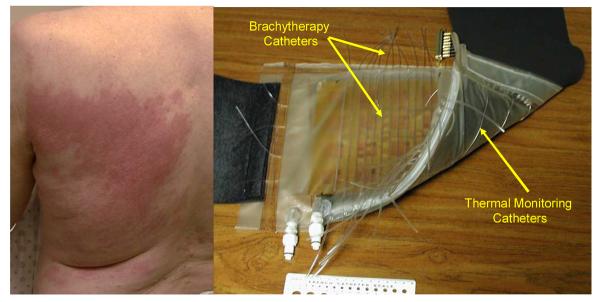
a. Typical pattern of the spreading of chestwall recurrence of breast cancer. The area is not easily and appropriately covered by current commercial devices. b. Picture of a rectangular vest with a 6 × 4 array of patch antenna. In the vest thermal monitoring and brachytherapy catheters are integrated with the water bolus. The multilayer jacket can be easily adjusted to the patient contour.
The use of an array of flexible material, as shown in fig. 1b, addresses the issue of comfort and effectiveness. Each antenna can be easily turned ON/OFF to achieve a desired 2D pattern of microwave power distribution. The water on the skin is kept at a constant temperature by the water bolus and its conditioning system which, in addition of controlling thickness of the bolus for better coupling of radiation and microwave energy, removes the air bubbles that would significantly affects the power deposition. The modulation of the water temperature also allow for a control of the depth profile, moving up and down the highest peak of the thermal distribution in the target tissue, allowing for a quasi=3D control of the heating pattern. However while the square antenna patches are ideal for compact and regular distribution of the heating elements, their shape is not suitable to contour the armpit, shoulder and neck region. The use of a fractionated thermal therapy to lower toxicity as in the case of radiation therapy and the limited cost of customizing parts of the jacket for a single patient undergoing multiple (5 or more) hyperthermia treatments justify the eventual use of patient specific pattern to avoid critical tissues.
Thus there is a need to better understand the functioning of multifed slot antennas and investigate their ability in delivering the microwave power in a specific heat deposition pattern. At the same time, the necessity of controlling the power delivered with the highest possible resolution while maintaining antenna efficiency not to overheat the feeding lines on the flexible substrate, justifies the need for a smaller antenna.
2.2 Theory behind the shaping of the dual concentric conductor
A basic dual concentric conductor antenna is shown in Fig.3a. As explained in [34], a voltage between the center patch and the ground plane can excite a radiating slot mode, which propagates into the tissue. The choice of square geometry is dictated by maximizing space utilization for most uniform power deposition patterns in array configurations. Extensive studies of a similar ring slot antenna configuration have been reported in the literature [35] as they are extensively used in radars and communications. The DCC aperture is a particular ring-slot configuration fed simultaneously on all four sides for optimum near-field power deposition in lossy media. Due to the variability of antenna loading as well as simultaneous feeding from the four sides makes the design of DCC antennas more difficult than standard slot radiators. The near field occurs in the Fresnel region, when r≤ 2D2/λm, where r is the distance from an antenna ofside D and λm is wavelength in the medium. In the case of a 3 cm × 3 cm square DCC antenna and muscle tissue (εr = 51) at 915 MHz, the boundary between near and far field is at approximately r = 7.8cm. To avoid unwanted phase addition between antennas, the array is not driven coherently, so the boundary is the same for a single antenna. Beyond the boundary in the Fraunhofer region, the angular far field distribution is independent of distance and power decays according to the inverse square law so use of a spherical coordinate system simplifies the mathematics.
Fig. 3.
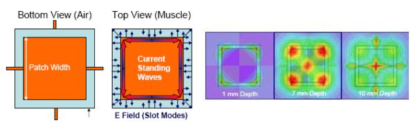
a. DCC antenna geometry, E fields in the ring slot and edge currents. b. Simulated SAR pattern in homogenous muscle tissue at different depths for a typical 3 cm × 3 cm DCC with a ring width of 2.5 mm
Such simplifications cannot be used in the near field however, as the evanescent terms become significant in the radiation pattern. So the study and design of the DCC relies heavily on numerical calculation and the power distribution can be better understood in a Cartesian coordinate system. In addition the evanescent fields are strongly affected by discontinuities close to the antenna, so feedlines and changes of dielectric properties in the materials above/below the slot can significantly change the radiated power pattern. Despise these challenges, operation of the antenna can be understood in relatively simple terms. Referring to Fig.3a, the current standing waves at the metal edges of the ring are responsible for the radiating modes. To first approximation, the fundamental radiating mode occurs when the E field inside the slot travels along the ring an amount close to one guided wavelength. λg. Accurate evaluation of the wavelength requires numerical calculation, since the slot radiates into the air in the backside and the muscle tissue in the front.
A very rough estimation of the effective permittivity, εeff ≈ (1+51)/2, leads to a value of λg ≈ 5.9 cm, which is half the typical DCC ring circumference. So the fundamental mode at which the 3 cm DCC antenna could radiate efficiently is approximately 450MHz. All multiples of that frequency will be also be able to radiate. On one hand this has a drawback: if the amplifier source, which usually is a solid state amplifier, operates in strong saturation and thus with a distorted signal, also the harmonics will be able to radiate efficiently causing alteration in the SAR pattern. On the other hand, the difference between each mode is the number of phase full rotation wave along the ring and this can be used to design a convenient current standing wave. When the patch is fed simultaneously from all four sides, the fields in the slots overlap. At 915 MHz the metal edge currents and the slot E field each travel a half wavelength to reach the next side feed, so the phase is rotated 180°. At the corners, the fields are rotated 90°. Thus there is a null at the center of each side and a maximum at each corner.
In addition, referring to Fig. 3b, as microwave currents accumulate at the edges and corners, the sharp corners of the square ring accentuate the field peaks. At the antenna-muscle interface, the pattern of radiated power, described by the Specific Absorption Rate (SAR) distribution, mimics the shape of the square slot – alternating maximum values at the corners and minima at the center of each side. In the center of the patch there is no power as the currents flow only along the patch edges. However, as they travel omnidirectionally deeper into muscle, the EM waves generated by the edge currents sum in the center of the patch forming a standing wave along the axis perpendicular to the antenna (z-axis). For a homogeneous medium, the typical SAR pattern is represented in Fig.3b. Note that due to the strong attenuation in muscle, it is common to describe the exponentially decreasing near field on z-planes at particular depths. This evaluation helps in designing antennas for most uniform temperature distribution across the DCC. This occurs when the peaks of the SAR are closed enough that the 50% of maximum SAR line at the target depth (usually 1cm) contours the largest area without significant dips, so that blood perfusion and thermal conduction will be able to smooth the temperature evenly across the target region.
2.3 Shaping the DCC
When designing a symmetric regular polygon, the feedlines must be located at the center of the sides of the polygon. In this way the symmetry causes the pattern to conform to the shape of the polygon. All the phases must be the same. As shown in Fig. 4a, the rules for optimal efficiency follow the same rules of a travelling wave device such an amplifier. The phases of the injection signal must coherently add up to the incoming wave. In that case there is maximum transfer of energy. Unfortunately, in the case of the DCC, this condition would force the slot antenna to be very large compromising the ability to smoothly contour the disease. Thus, at the expense of optimal efficiency, the size of the antenna is reduced, but if the antenna does not shrink too much, the travelling wave still gains from the injected power. The corners, as shown in Fig 4.b are always at the highest energy peak due to symmetry.
Fig. 4.
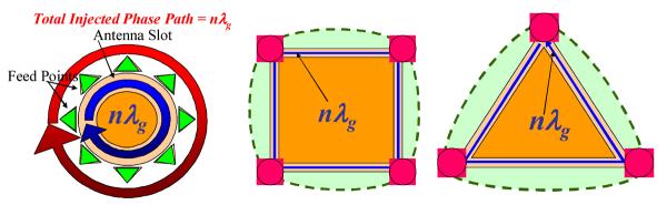
a. Travelling wave conditions for slot antennas: Each feed signal is injected in phase with the traveling wave. b. and c. The near field SAR peaks at slot corners (highest currents) and the radiated power is distributed according to the slot shape
Changing relative phases or location can cause asymmetry of the pattern. We simulated several shapes and the results are presented below. The model used for our simulation included a target 1cm deep, as shown in Fig. 5a. Fig. 5b shows the results of the simulated SAR pattern at 5mm depth in the treated tissue. The addition of a 5mm bolus clearly smoothens the shape, but the overall power deposition is acceptable considering that the treatment region is usually right at the surface of the skin.
Fig. 5.
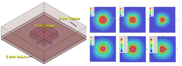
a. Model setup for Ansoft HFSS simulations. The target is 1cm thick and is located from the surface of the skin with or without the water bolus of 5mm. b. SAR at 5mm in tissue of various shape designed close to the travelling wave conditions with and without the bolus. A thicker bolus clearly smoothens the shape.
2.4 Optimal size of the DCC
The size of each of the DCC was also optimized. As the side length changes, the power deposition is affected. As expected, what actually counts is the overall perimeter of the slot. Independently of the shape and the number of sides, the optimal perimeter is 10cm. When the model contains a more complex target medium, which includes skin and all the plastics of the jackets, the optimal perimeter length is 10–12 cm. As mentioned before, while the square antenna provides the best compacting and uniformity properties, it is not most efficient since the total power in the target increases with the number of turns. As the polygon approaches the circular pattern, the power deposited reaches its optimal value. However a circular pattern does allow a tight fitting of array elements.
Finally, as shown in Fig. 7, as the side of the array changes, the SAR at 5mm depth also changes shape and value. When the antenna size is not close to the optimal values, the SAR pattern is also far from the ideally shaped power distribution as shown in Fig 8a and 8b.
Fig. 7.
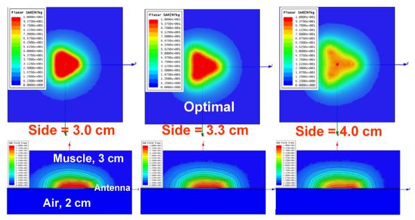
Depth profile for various sized triangular DCC for a 5mm depth plane
Fig. 8.
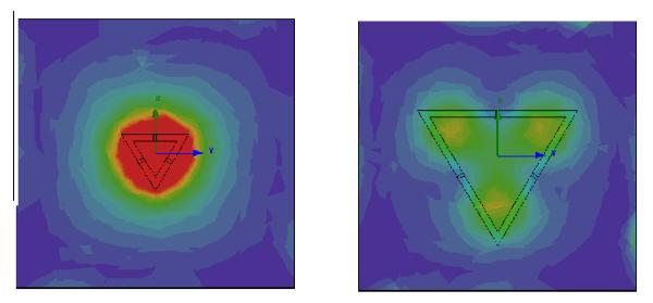
a. Depth profile for non-optimal size: a. A DCC too small has a bad shape but good SAR. b. A DCC too large has a good shape but low power
3. CONCLUSION
Dual concentric conductor antennas (DCCs) have been proposed as effective radiators for microwave hyperthermia applications, due to simplicity of construction from flexible printed circuit board (PCB) material. With proper design, the power deposition (SAR) pattern is uniform across the DCC. Array of DCC address the issue of patient comfort and adequate coverage of the tumor area. However special design of the DCC is required to adequately treat the areas close to the neck and avoid critical regions like flaps and blisters. In this paper the theory of resize and reshape multifed slot antennas for superficial disease is presented. It is shown that, independently on the shape of the antenna, the overall slot length is the determining factor for optimal shape reconstruction at depth and efficient power deposition. A total perimeter length of 10–12 cm is shown to be optimal for slot antenna designed for 915MHz. It is also shown that the total power deposited in the target area increases as the number of sides increases in polygonal-shaped DCCs to achieve a maximum for circular slots which do not compact easily in an array. The results have been applied in a clinical prototype that is expected to significantly improve the coverage of critical areas while sparing viable tissue and reducing patient discomfort
Fig. 2.
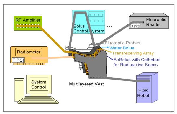
Schematic diagram of hybrid hyperthermia system capable of delivering simultaneous heat and radiation. Patient can hop on a linear accelerator table during heating or use with HDR afterloading surface conforming template for simultaneous or immediately sequential HT-RT therapy. The multilayer jacket can be easily adjusted to the patient cuntour
Fig. 6a.
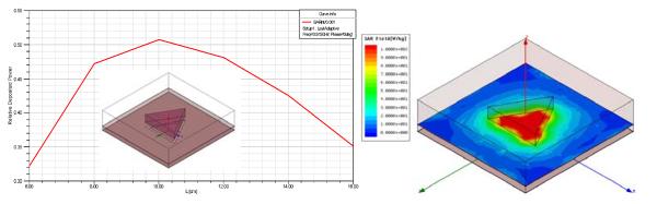
Total relative power deposited in the target. The optimal perimeter length is 10 cm independently on the number of sides. For 10cm perimeter, desired shape and good power deposition is achieved
Fig. 6b.
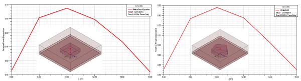
As the number of sides increases, the total relative power deposited in the target at the optimal perimeter length increases. Circular pattern would offer less ability to compact in an array but better power efficiency.
ACKNOWLEDGEMENT
This effort was supported by NIH Grants R44 CA104061 and RO1 CA70761.
REFERENCES
- [1].Cancer facts and figures 2005. American Cancer Society; 2005. [Google Scholar]
- [2].Chen K, Montague E, Oswald M. Results of irradiation in the treatment of loco-regional breast cancer recurrence. Cancer. 1985;56:1269–1273. doi: 10.1002/1097-0142(19850915)56:6<1269::aid-cncr2820560608>3.0.co;2-y. [DOI] [PubMed] [Google Scholar]
- [3].Janjan N, et al. Management of locoregional recurrent breast cancer. Cancer. 1986;58:1552–1556. doi: 10.1002/1097-0142(19861001)58:7<1552::aid-cncr2820580728>3.0.co;2-w. [DOI] [PubMed] [Google Scholar]
- [4].Kapp DS. Efficacy of adjuvant hyperthermia in the treatment of superficial recurrent breast cancer: confirmation and future directions. International Journal of Radiation Oncology, Biology and Physics. 1996;35(5):1117–21. doi: 10.1016/0360-3016(96)00288-x. [DOI] [PubMed] [Google Scholar]
- [5].Kapp DS, et al. Thermoradiotherapy for residual microscopic cancer: elective or post-excisional hyperthermia and radiation therapy in the management of local-regional recurrent breast cancer. International Journal of Radiation Oncology, Biology, Physics. 1992;24(2):261–277. doi: 10.1016/0360-3016(92)90681-7. [DOI] [PubMed] [Google Scholar]
- [6].Kapp DS, Meyer JL. Breast cancer: chest wall hyperthermia-electron beam therapy. Frontiers of Radiation Therapy and Oncology. 1991;25(6):151–168. doi: 10.1159/000429586. discussion 180–2. [DOI] [PubMed] [Google Scholar]
- [7].Marcial VA. The role of radiation therapy in the multidisciplinary management of recurrent and metastatic breast cancer. Cancer. 1994;74(1):450–452. doi: 10.1002/cncr.2820741334. [DOI] [PubMed] [Google Scholar]
- [8].Donegan W, Perez-Mesa C, Watson F. A biostatistical study of local recurrent breast cancer. Surgery, Gynecology, and Obstetrics. 1966;122(3):529–540. [PubMed] [Google Scholar]
- [9].Leonard R, et al. Randomized, double-blind, placebo controlled multicenter trial of 6% Miltefosine solution, a topical chemotherapy in cutaneous metastases from breast cancer. American Journal of Clinical Oncology. 2001;19(21):4150–4159. doi: 10.1200/JCO.2001.19.21.4150. [DOI] [PubMed] [Google Scholar]
- [10].Rauschecker H, et al. Systemic therapy for treating locoregional recurrence in women with breast cancer. Cochrane Database Syst Rev. 2001;4:CD002195. doi: 10.1002/14651858.CD002195. [DOI] [PMC free article] [PubMed] [Google Scholar]
- [11].Taylor ME. Breast cancer: chest wall recurrences. Current Treatment Options Oncology. 2002;3:175–177. doi: 10.1007/s11864-002-0063-7. [DOI] [PubMed] [Google Scholar]
- [12].Zimmerman KW, Montague ED, Fletcher H. Frequency, anatomical distribution and management of local recurrences after definitive tehrapy for breast cancer. Cancer. 1966;19:67–74. doi: 10.1002/1097-0142(196601)19:1<67::aid-cncr2820190107>3.0.co;2-2. [DOI] [PubMed] [Google Scholar]
- [13].Henderson I, et al. In: Cancer of the breast, in Cancer: Principles and Practice of Oncology. 3rd Ed DeVita VJ, Hellman S, Rosenberg S, editors. JB Lippincott Co.; Philadelphia: 1989. pp. 1197–1249. [Google Scholar]
- [14].Bedwinek J. Radiation therapy of isolated local-regional recurrence of breast cancer: decisions regarding dose, field size, and elective irradiation of uninvolved sites. Int J Radiat Oncol Biol Phys. 1990;19(4):1093–5. doi: 10.1016/0360-3016(90)90040-q. [DOI] [PubMed] [Google Scholar]
- [15].Bedwinek JM, et al. Prognostic indications in patients with isolated local-regional recurrence of breast cancer. Cancer. 1981;47:2232–2235. doi: 10.1002/1097-0142(19810501)47:9<2232::aid-cncr2820470921>3.0.co;2-r. [DOI] [PubMed] [Google Scholar]
- [16].Stauffer PR. Evolving technology for thermal therapy of cancer. International Journal of Hyperthermia. 2005;21(8):731–744. doi: 10.1080/02656730500331868. [DOI] [PubMed] [Google Scholar]
- [17].Stauffer PR, Diederich CJ, Pouliot J. In: Thermal Therapy for Cancer, in Brachytherapy Physics. 2nd Ed. joint AAPM/ABS Summer School, editor. Thomadsen, Rivard, and Butler; 2005. pp. 901–932. [Google Scholar]
- [18].Overgaard J. Simultaneous and sequential hyperthermia and radiation treatment of an experimental tumor and its surrounding normal tissue in vivo. International Journal of Radiation Oncology Biology Physics. 1980;6:1507–1517. doi: 10.1016/0360-3016(80)90008-5. [DOI] [PubMed] [Google Scholar]
- [19].Perez CA, et al. Clinical results of irradiation combined with local hyperthermia. Cancer. 1983;52:1597–1603. doi: 10.1002/1097-0142(19831101)52:9<1597::aid-cncr2820520910>3.0.co;2-n. [DOI] [PubMed] [Google Scholar]
- [20].Sneed PK, et al. Survival benefit of hyperthermia in a prospective randomized trial of brachytherapy boost +/− hyperthermia for glioblastoma multiforme. International Journal of Radiation Oncology, Biology and Physics. 1998;40(2):287–295. doi: 10.1016/s0360-3016(97)00731-1. [DOI] [PubMed] [Google Scholar]
- [21].Valdagni R, Amichetti M. Report of long-term follow-up in a randomized trial comparing radiation therapy and radiation therapy plus hyperthermia to metastatic lymph nodes in stage IV head and neck patients. International Journal of Radiation Oncology Biology Physics. 1994;28:163–169. doi: 10.1016/0360-3016(94)90154-6. [DOI] [PubMed] [Google Scholar]
- [22].Van der Zee J, et al. Comparison of radiotherapy alone with radiotherapy plus hyperthermia in locally advanced pelvic tumours: a prospective, randomised, multicentre trial. Lancet. 2000;355:1119–1125. doi: 10.1016/s0140-6736(00)02059-6. [DOI] [PubMed] [Google Scholar]
- [23].Vernon CC, et al. Radiotherapy with or without hyperthermia in the treatment of superficial localized breast cancer: Results from five randomized controlled trials. International Journal of Radiation Oncology, Biology and Physics. 1996;35(4):731–744. doi: 10.1016/0360-3016(96)00154-x. [DOI] [PubMed] [Google Scholar]
- [24].Jones E, et al. Randomized trial of hyperthermia and radiation for superficial tumors. Journal of Clinical Oncology. 2005;23(13):3079–3085. doi: 10.1200/JCO.2005.05.520. [DOI] [PubMed] [Google Scholar]
- [25].Perez CA, et al. Quality assurance problems in clinical hyperthermia and their impact on therapeutic outcome: a report by the Radiation Therapy Oncology Group. International Journal of Radiation Oncology, Biology and Physics. 1989;16:551–558. doi: 10.1016/0360-3016(89)90471-9. [DOI] [PubMed] [Google Scholar]
- [26].Stauffer PR, et al. Progress on Conformal Microwave Array Applicators for Heating Chestwall Disease. Thermal Treatment of Tissue: Energy Delivery and Assessment IV, Proc. of SPIE. 2007 [Google Scholar]
- [27].Dewey WC, et al. In: Cell biology of hyperthermia and radiation, in Radiation Biology in Cancer Research. Meyn RE, Withers HR, editors. Raven Press; New York: 1980. pp. 589–621. [Google Scholar]
- [28].Overgaard J. The current and potential role of hyperthermia in radiotherapy. International Journal of Radiation Oncology Biology Physics. 1989;16:535–549. doi: 10.1016/0360-3016(89)90470-7. [DOI] [PubMed] [Google Scholar]
- [29].Moros EG, et al. Simultaneous delivery of electron beam therapy and ultrasound hyperthermia utilizing scanning reflectors: a feasibility study. International Journal of Radiation Oncology Biology Physics. 1995;31(4):893–904. doi: 10.1016/0360-3016(94)00469-2. [DOI] [PubMed] [Google Scholar]
- [30].Moros EG, Straube WL, Myerson RJ. Devices and techniques for the clinical application of concomitant heat and ionizing radiation by external means. Biomedical Engineering, Application, Basis, Communications. 1994;6:328–339. [Google Scholar]
- [31].Myerson RJ, et al. Simultaneous superficial hyperthermia and external radiotherapy: Report of thermal dosimetry and tolerance to treatment. Int J Hyperthermia. 1999;15:251–266. doi: 10.1080/026567399285639. [DOI] [PubMed] [Google Scholar]
- [32].Taschereau R, et al. Radiation dosimetry of a conformal heat-brachytherapy applicator. Technology in Cancer Research and Treatment. 2004;3(4):347–358. doi: 10.1177/153303460400300404. [DOI] [PubMed] [Google Scholar]
- [33].Juang T, et al. Multilayer conformal applicator for microwave heating and brachytherapy treatment of superficial tissue disease. International Journal of Hyperthermia. 2006;22(7):527–544. doi: 10.1080/02656730600931815. [DOI] [PubMed] [Google Scholar]
- [34].Maccarini PF, Rolfsnes H-O, Neuman D, Stauffer P. Optimization of a dual concentric conductor antenna for superficial hyperthermia applications. Engineering in Medicine and Biology Society, 2004. IEMBS '04. 26th Annual International Conference of the IEEE; [DOI] [PubMed] [Google Scholar]
- [35].Tehrani H, Chang K. Multifrequency Operation of Microstrip Fed Slot Ring Antennas on Thin Low Dielectric Permittivity Substrates. IEEE Trans. on Antennas and Propagation. 2002 Sep;50(no.9):1299–1308. [Google Scholar]
- [36].Rossetto F, Diederich CJ, Stauffer PR. Thermal and SAR characterization of multielement dual concentric conductor microwave applicators for hyperthermia, a theoretical investigation. Medical Physics. 2000;27(4):745–753. doi: 10.1118/1.598937. [DOI] [PubMed] [Google Scholar]
- [37].Rossetto F, Stauffer PR. Effect of complex bolus-tissue load configurations on SAR distributions from dual concentric conductor applicators. IEEE Transactions on Biomedical Engineering. 1999;46(11):1310–1319. doi: 10.1109/10.797991. [DOI] [PubMed] [Google Scholar]