Abstract
In this paper we investigate computationally the transient dynamics of an elastic capsule flowing in a square microchannel with a rectangular constriction, and compare it with that of a droplet. The confinement and expansion dynamics of the fluid flow results in a rich deformation behavior for the capsule, from an elongated shape at the constriction entrance, to a flattened parachute shape at its exit. Larger capsules are shown to take more time to pass the constriction and cause higher additional pressure difference, owing to higher flow blocking. Our work highlights the effects of two different mechanisms for non-tank-treading transient capsule dynamics. The capsule deformation results from the combined effects of the surrounding and inner fluids’ normal stresses on the soft particle’s interface, and thus when the capsule viscosity increases, its transient deformation decreases, as for droplets. However, the capsule deformation is not able to create a strong enough inner circulation (owing to restrictions imposed by the material membrane), and thus the viscosity ratio does not affect much the capsule velocity and the additional pressure difference. In addition, the weak inner circulation results in a positive additional pressure difference ΔP+ even for low-viscosity capsules, in direct contrast to low-viscosity droplets which create a negative ΔP+. Our findings suggest that the high cytoplasmatic viscosity, owing to the protein hemoglobin required for oxygen transport, does not affect adversely the motion of non-tank-trading erythrocytes in vascular capillaries.
1. INTRODUCTION
The study of the interfacial dynamics of artificial or physiological capsules (i.e. membrane-enclosed fluid volumes) in viscous flows has seen an increased interest during the last few decades due to their numerous engineering and biomedical applications [31, 32]. In the area of interest of the present paper, the study of the motion and deformation of capsules and biological cells in microfluidic channels is motivated by a wide range of applications including drug delivery, cell sorting and cell characterization devices [1-3, 8, 11, 17, 39], fabrication of microparticles and microcapsules with desirable properties [9, 21, 26, 37], determination of membrane properties [25, 33], and of course its similarity to blood flow in vascular capillaries [31].
Therefore, studying the dynamics of soft particles in confined solid ducts, such as microfluidic channels and blood microvessels, provides useful information on the utilization of these particles in chemical, pharmaceutical and physiological processes. For example, understanding the stability of soft particle shapes provides helpful insight on the hydrodynamic aggregation and the effective viscosity of suspensions [10]. The deformation of artificial capsules in microchannels is directly associated with drug delivery, cell sorting and cell characterization [1, 2]. Furthermore, the deformability of red blood cells plays a pivotal role in the oxygen and carbon dioxide exchange between the microcirculation and the body tissues [31], and helps identifying the effects of blood disorders and diseases [3, 16, 39]. Studying the motion of capsules in micro-constrictions is further motivated by its similarity to the erythrocyte motion over endothelial cells and adherent leukocytes in vascular capillary vessels as well as other attached protuberances of biological nature such as those formed during cancer cell metastasis and biofilm formation [18, 38, 44, 45].
The deformation of capsules and biological cells in solid ducts is determined by the nonlinear coupling of the deforming hydrodynamic forces with the restoring interfacial forces of the particle membrane. Since the latter forces depend on the type of the soft-particle interface, this suggests that different soft particles (such as droplets, capsules, vesicles and erythrocytes) may obtain quite different shapes as they travel in a solid vessel [6, 10, 23, 27]. Their possible differences are further augmented by the strength of the inner circulation, which depends on the type of the particle interface, and which affects strongly the particle velocity and additional pressure difference. Thus, low-viscosity droplets with a significant inner circulation cause a negative pressure difference and thus facilitate their flow requirements; the opposite happens for high-viscosity droplets where the inner circulation is weak [20, 24, 30]. Furthermore, the development of a four-vortex pattern on the fluid-incompressible vesicle membrane (and the associated inner circulation) results in an unexpected croissant shape (relatively wider in the narrowest direction of the channel) for vesicles in rectangular microfluidic channels [10].
In this paper we investigate computationally the transient dynamics of an elastic capsule flowing along the centerline of a square microchannel with a rectangular constriction. The confinement and the expansion dynamics of the fluid flow results in a rich deformation behavior for the capsule as it moves inside the microfluidic device, from an elongated shape at the constriction entrance, to a flattened parachute shape at its exit. Larger capsules are shown to take more time to pass the constriction and cause higher additional pressure difference, owing to higher flow blocking.
Most important, our work highlights the effects of two different mechanisms for non-tank-treading transient capsule dynamics. The capsule deformation results from the combined effects of the surrounding and inner fluids’ normal stresses on the soft particle’s interface, and thus when the capsule viscosity increases, its transient deformation decreases, as for droplets. However, the capsule deformation is not able to create a strong enough inner circulation (owing to restrictions imposed by the material membrane), and thus the viscosity ratio does not affect much the capsule velocity and the additional pressure difference. In addition, the weak inner circulation results in a positive additional pressure difference ΔP+ even for low-viscosity capsules, in direct contrast to low-viscosity droplets which create a negative ΔP+. Our findings suggest that the high cytoplasmatic viscosity, owing to the protein hemoglobin required for oxygen transport, does not affect adversely the velocity of non-tank-trading erythrocytes in vascular capillaries nor impose any additional energy requirement for the cells flow.
2. PROBLEM DESCRIPTION
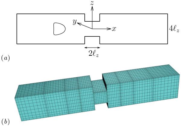
We consider a three-dimensional capsule (with a spherical undisturbed shape and an elastic interface) flowing along the centerline of a square microchannel with a rectangular constriction in the middle, as shown in figure 1. To facilitate our description, we imagine that the channel is horizontal as illustrated in figure 1(a). Thus, the flow direction (i.e. the x-axis) corresponds to the channel’s or capsule’s length, the z-direction will be referred as height while the y-direction will be referred as width. The height of the constriction is 2ℓz and that of the channel is 4ℓz. Both the constriction and the channel have width 4ℓz. The rectangular constriction has length 2ℓz while the length of the entire microfluidic device is 20ℓz. The constriction half-height ℓz serves as the length scale for the present problem while the origin of the co-ordinate system is placed in the middle of the rectangular constriction as shown in figure 1(a).
FIG. 1.
(a) Illustration of an elastic capsule flowing at the centerline of a square microchannel with a rectangular constriction. (b) Spectral boundary element discretization of the microfluidic geometry.
The capsule’s interior and exterior are Newtonian fluids, with viscosities λμ and μ, and the same density. The capsule size a is specified by its volume V = 4πa3/3 and is comparable (or smaller) to the constriction half-height ℓz. In addition, we consider that the capsule is slightly over-inflated, made of a strain-hardening membrane following the Skalak et al. constitutive law [40] (and thus called Skalak capsule in this paper) with comparable shearing and area-dilatation resistance. This capsule description represents well bioartificial capsules such as the capsules made of covalently linked human serum albumin (HSA) and alginate used in the experimental study of Risso, Collé-Pailot and Zagzoule [36].
For a membrane with shearing and area-dilatation resistance considered in this work, the surface stress is determined by the in-plane stresses, i.e. Δf = −∇s · τ which in contravariant form gives
| (1) |
where the Greek indices range over 1 and 2, while Einstein notation is employed for (every two) repeated indices. In this equation, the ταβ|α notation denotes covariant differentiation, tβ = ∂x/∂θβ are the tangent vectors on the capsule surface described with arbitrary curvilinear coordinates θβ, and bαβ is the surface curvature tensor [14, 32].
The in-plane stress tensor τ is described by constitutive laws that depend on the material composition of the membrane. In this work, we employ the Skalak et al. law [40] which relates τ’s eigenvalues (or principal elastic tensions , β = 1, 2) with the principal stretch ratios λβ by
| (2) |
Note that the reference shape of the elastic tensions is the spherical quiescent shape of the capsule while to calculate reverse the λβ subscripts. In Eq.(2), Gs is the membrane’s shearing modulus while the dimensionless parameter C is associated with the area-dilatation modulus Ga of the membrane (scaled with its shearing modulus) [32, 40].
To quantify the capsule over-inflation, we define the prestress parameter αp such that all lengths in the undeformed capsule would be scaled by (1+αp), relative to the reference shape [22]. Since the capsule is initially spherical, its membrane is initially prestressed by an isotropic elastic tension which depends on the employed constitutive law and its parameters but not on the capsule size. For example, for a Skalak capsule with C = 1 and αp = 0.05, the undisturbed capsule size a is 5% higher than that of the reference shape and the initial membrane tension owing to prestress is τ0/Gs ≈ 0.3401.
At time t = 0 the capsule is located at −4ℓz, the flow is turn on inside the microfluidic device and we investigate the transient dynamics of the capsule as it enters and exits the constriction which occupies the x-region [−ℓz, ℓz]. Far from the capsule, the flow approaches the undisturbed flow u∞ in the square channel characterized by an average velocity . (The exact form of the channel’s velocity field u∞ and its average velocity are given in section 2 of our recent paper on capsule motion in a square microchannel [22].) We assume that the Reynolds number is small for both the surrounding and the inner flows, and thus the capsule deformation occurs in the Stokes regime.
The numerical solution of the interfacial problem is achieved through our interfacial spectral boundary element method for membranes, and the interested reader is referred to our earlier papers for more details on our spectral algorithm and our recent investigation on the capsule dynamics in square and rectangular microchannels [14, 22, 23]. To verify the accuracy of our results, we performed convergence runs covering the entire interfacial evolution (i.e. well past steady state) with different spacial grids for several capsules and flow rates. Our convergence runs showed that our results for the interfacial shape, the capsule velocity and the additional pressure difference presented in this work were determined with an accuracy of at least 3 significant digits.
In our work we assume that the flow rate Q inside the micro-device is fixed. In addition, we consider a Skalak capsule with prestress αp = 0.05 (or τ0/Gs ≈ 0.3401) and membrane hardness C = 1. In section 3 we study the interfacial dynamics for equiviscous capsules (i.e. for viscosity ratio λ = 1) and different sizes or flow rates. The effects of viscosity ratio λ are investigated in section 4. The present problem depends on two additional dimensionless parameters: the capsule size (relatively to the constriction height) a/ℓz, and the capillary number Ca defined as
| (3) |
where is the average undisturbed velocity in the square microchannel. It is of interest to note that the capillary number, as defined by Eq.(3), does not contain any length scale, and thus it may be considered as a dimensionless flow rate. In this study, the velocity is scaled with the average undisturbed velocity and the pressure with the associated pressure scale, , in the square channel.
The range of dimensionless parameters employed in our computational work (shown in table 1) can readily be used in experimental microfluidic systems. As an example, Leclerc et al. [25] investigated ovalbumin microcapsules with shear modulus Gs = 0.07N/m in microfluidic channels with a typical height ℓz = 50 μm. Using as external fluid glycerin with viscosity μ ≈ 1 Pa s and average velocities , the authors achieved capillary numbers in the range Ca ≈ 0.1–0.5. Considering erythrocytes with shear modulus Gs = 2.5 μN/m [13, 19] in microfluidic channels with height ℓz = O(10) μm and an external liquid with a viscosity similar to that of water, μ ≈ 1 m Pa s, the same range of capillary numbers can be achieved with average velocities .
TABLE 1.
Range of parameters studied in this work. The capsule hardness is C = 1 and its prestress αp = 0.05 (or τ0/Gs ≈ 0.3401).
| Varying parameter | Fixed parameters |
|---|---|
| a/ℓz = 0.4–1 | Ca = 0.1, λ = 1 |
| Ca = 0.01–0.1 | a/ℓz = 0.7, 1, λ = 1 |
| λ = 0.01-5 | a/ℓz = 0.7, 0.9, Ca = 0.1 |
3. CONSTRICTION DYNAMICS FOR EQUIVISCOUS CAPSULES
In this section we investigate the transient dynamics of a viscous capsule (with viscosity ratio λ = 1) as it passes through the microfluidic constriction. We consider a wide range of capsule sizes a, comparable or smaller to the constriction half-length (i.e. a/ℓz = 0.4–1) in weak and moderate flow rates Ca. Our results, including the capsule lengths, its velocity Ux and the additional pressure difference ΔP+ due to the capsule presence, are expressed as functions of the capsule centroid xc.
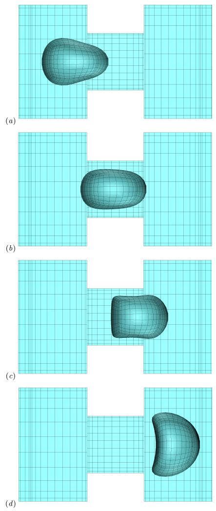
The shape of a Skalak capsule as it flows inside the micro-device is shown in figure 2. The bullet-like shape of the capsule obtained initially at the left-side of the square channel, e.g. [22], becomes more pointed as the capsule approaches the constriction as shown in figure 2(a). This is due to the strong hydrodynamic forces associated with the cross-sectional area decrease which doubles the average fluid velocity inside the constriction since the flow rate Q is fixed in our problem. To balance the deforming hydrodynamic forces, the capsule tries to increase its downstream curvature and decrease its upstream curvature so that the total restoring tension force on the membrane is increased. In essence, this capsule deformation results from the curvature term in the membrane traction, Eq.(1), as we identified in our earlier studies on capsule dynamics in planar extensional flows or in microfluidic channels [14, 22, 23].
FIG. 2.
The shape of a Skalak capsule with C = 1, a/ℓz = 1, λ = 1 and Ca = 0.1 moving inside the microfluidic constriction. The capsule’s centroid xc/ℓz is (a) −1.51, (b) −0.1, (c) 0.81, and (d) 2.05. The three-dimensional capsule views were derived from the actual spectral grid using orthographic projection in plotting.
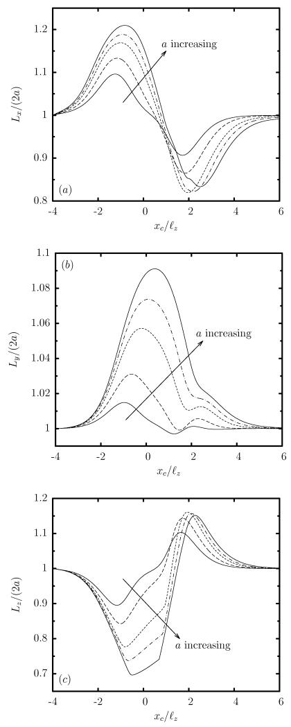
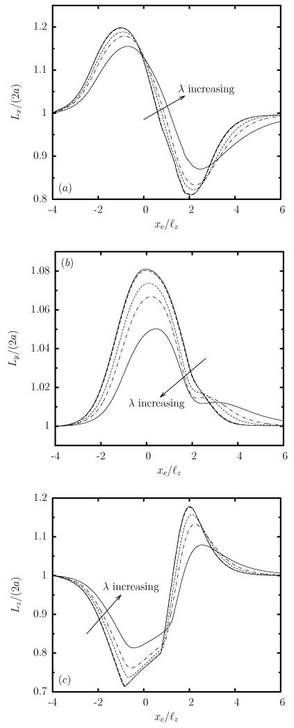
Thus as the capsule approaches the constriction, its length Lx is increased while its height Lz is decreased considerably, as seen in figure 3(a,c). At the same time the capsule width Ly is increased as shown in figure 3(b) and thus the capsule tries to occupy a larger area along the less-confined width of the rectangular constriction. This deformation is consistent with the steady-state capsule shape in rectangular channels where the capsule extends significantly in the less-confined lateral direction of the channel cross-section owing to the development of strong lateral tensions on the capsule membrane required for interfacial stability [23].
FIG. 3.
Evolution of the capsule lengths as a function of the centroid xc, for a Skalak capsule with C = 1, Ca = 0.1 and λ = 1, for size a/ℓz = 0.4, 0.6, 0.8, 0.9, 1. (a) Length Lx, (b) width Ly, and (c) height Lz (scaled with the length 2a of the undisturbed spherical shape). These lengths are determined as the maximum distance of the interface in the x, y and z directions.
When the capsule is inside the constriction, i.e. its centroid is nearly xc = 0 as in figure 2(b), the capsule has obtained a shape similar to the peddle-like shape characteristic of capsule motion in rectangular channels [23]. This capsule shape involves elongation in the flow and lateral directions, i.e. increased length Lx and Ly, and a significant decrease in its height Lz, as shown in figure 3.
As the capsule moves out of the constriction seen in figure 2(c), its downstream portion lies at the right-side of the square channel and thus it experiences the dynamics of the cross-section expansion, i.e. the sudden drop of the average fluid velocity. Thus the downstream portion of the capsule slows down; however, its upstream part is still inside the constriction and moves with the faster velocity of the constriction. Both actions result in a compression of the capsule shape and thus in a significant reduction of the capsule length Lx accompanied with a fast increase of its height Lz, as shown in figure 3. This expansion effect is much more pronounced as the capsule completely exits the constriction where it obtains a very flattened three-dimensional parachute-like shape, presented in figure 2(d), characterized by a higher height Lz compared to its length Lx. (See also the capsule lengths in figure 3 when the capsule centroid is nearly xc = 2.) After this peak, the capsule relaxes towards a bullet shape in the square channel far downstream of the constriction.
Therefore, the two distinct regimes associated with the microfluidic constriction, i.e. confinement and expansion, result in two distinct interfacial shapes. In the confinement regime, the capsule obtains an elongated bullet shape where its length Lx obtains a maximum value and its height Lz a minimum value. The opposite happens during the expansion dynamics where the capsule obtains a flattened parachute shape. Similar deformation has been observed in axisymmetric constrictions where the capsule width is identical to its height (i.e. Ly = Lz) due to the axisymmetry [35].
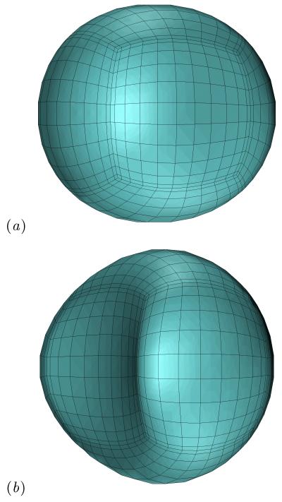
The confinement dynamics are more pronounced as the capsule size a is increased as shown in figure 3, since then the capsule occupies a larger volume and thus causes a higher flow blocking. It is of interest to note that due to the rectangular constriction, both the confinement and expansion dynamics are associated with an elongated capsule width Ly, which increases monotonically with the size a, as seen in figure 3(b). Therefore, the constriction cross-sectional asymmetry results in a highly non-axisymmetric, fully three-dimensional capsule shape (as shown in figure 4), which cannot be described from single-view observations as commonly happens in microfluidic experiments or based on axisymmetric or two-dimensional computations.
FIG. 4.
The shape of a Skalak capsule with C = 1, a/ℓz = 1, λ = 1 and Ca = 0.1 moving inside the microfluidic constriction for capsule’s centroid (a) xc/ℓz = −1.51 and (b) xc/ℓz = 2.05. The capsule shape is plotted as seen slightly askew from the positive z-axis to reveal its fully three-dimensional conformation.
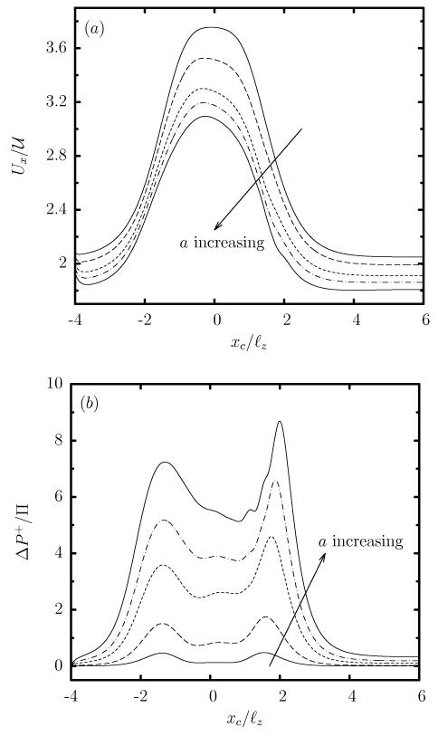
In addition, the larger capsule size a (or flow blocking) causes a monotonic decrease of the capsule velocity velocity Ux and an increase of the additional pressure difference ΔP+ as seen in figure 5. Observe that for the equiviscous (λ = 1) capsules studied in this section, the additional pressure difference ΔP+ is positive (as also happens for viscous droplets [30]) and thus the capsule presence results in higher energy requirements to maintain a constant flow rate.
FIG. 5.
Evolution of (a) the capsule velocity Ux, and (b) the additional pressure difference ΔP+, as a function of the centroid xc, for a Skalak capsule with C = 1, Ca = 0.1 and λ = 1, for size a/ℓz = 0.4, 0.6, 0.8, 0.9, 1.
We emphasize that the effects of decreasing the flow rate Ca (for a given capsule size) are similar to that of increasing the capsule size a (for a given flow rate), since both types of experiments result in a higher flow blocking in the former case due to the reduced interfacial deformation. Thus our results for the flow rate effects for a given capsule size (in particular for Ca = 0.01–0.1 and a/ℓz = 0.7, 0.9) are omitted.
The monotonic variation of the capsule velocity Ux and the additional pressure difference ΔP+ with the capsule size a or flow rate Ca can be understood by utilizing the scaling behavior we developed for capsule motion in a straight channel [22]. We emphasize that our earlier analysis was valid for steady-state capsule motion in straight solid ducts while the current problem involve transient dynamics. However, our computational findings presented in figure 5 clearly indicate that the transient dynamics over the entire micro-device scale as the capsule dynamics inside the constriction (e.g. see figure 2(c)) which is similar to the dynamics in a straight solid duct. Our conclusion for the current problem is further reinforced by the quasi-steady nature of the Stokes flow.
Therefore, utilizing Eqs.(19) and (27) from our previous investigation, Ref.[22], for capsules with size a comparable to the constriction size ℓz, the capsule velocity inside the constriction should scale proportionally with the gap h between the capsule surface and the solid walls,
| (4) |
(where is the average undisturbed velocity in the rectangular constriction), while the additional pressure difference should be inversely proportional to the gap,
| (5) |
It is of interest to note that Eqs.(4) and (5) are formally valid for cylindrical channels, and thus they represent only qualitatively the present problem by considering the gap h between the capsule surface and the solid walls in the xz-plane where the strongest hydrodynamic forces occur owing to the rectangular constriction. As the capsule size a increases (or as the flow rate Ca decreases), the gap h between the capsule surface and the solid walls decreases, and thus the capsule velocity decreases while the additional pressure difference ΔP+ increases, in agreement with our computational results shown in figure 5.
4. EFFECTS OF VISCOSITY RATIO
In this section we investigate the effects of viscosity ratio λ on the transient dynamics of a capsule as it passes through the microfluidic constriction. For this, we consider a capsule with a fixed size a/ℓz = 0.9 and capillary number Ca = 0.1, while we vary the viscosity ratio in the range λ = 0–5, i.e. we investigate from inviscid to very viscous capsules.
Figure 6 shows that, for any viscosity ratio, the evolution of the capsule dimensions is similar to that for an equiviscous capsule discussed in section 3. In addition, the figure reveals that both in the confinement and the expansion area (i.e. as the capsule enters or exits the constriction), its deformation decreases with the viscosity ratio. However, during the final relaxation stage towards the bullet shape in the square channel far downstream from the constriction, it is the very viscous capsule with λ = 5 which is more deformed since capsules with smaller viscosity ratio relax faster.
FIG. 6.
Evolution of the capsule lengths as a function of the centroid xc, for a Skalak capsule with C = 1, a/ℓz = 0.9 and Ca = 0.1, for viscosity ratio λ = 0.01, 0.1, 1, 2, 5. (a) Length Lx, (b) width Ly, and (c) height Lz (scaled with the length 2a of the undisturbed spherical shape). Our results for λ = 0.01 are identical for lower viscosity ratios, e.g. λ = 0.001, 0, and thus represent the low-viscosity limit λ << 1.
To explain the effects of the viscosity ratio on the capsule deformation, we need to consider that the capsule is deformed owing to the combined effects of the surrounding and inner fluids’ normal stresses on the capsule interface. Therefore, the capsule transient dynamics is characterized by the membrane time scale necessary to reach steady state, which for a given membrane hardness C is given by
| (6) |
where is the flow time scale. (More details on this time scale are given in the Appendix.) For low enough viscosity ratio, e.g. for λ ≤ 0.01 in our problem, the inner fluid does not practically participate in the transient dynamics, and thus all low-viscosity capsules show identical evolution, in agreement with our computational results shown in figure 6. For moderate viscosity ratios, λ = O(1), both the inner and the surrounding fluids affect the capsule deformation, while for very viscous capsules (e.g. λ = 5), it is the inner fluid which mostly affects the capsule deformation.
As the viscosity ratio λ increases, the time necessary for the capsule to react to the flow changes imposed by the constriction (i.e. the time scale τm) is increased. This makes the deformation rate slower and thus the capsule’s transient deformation decreases with the viscosity ratio as seen in figure 6. For the same reason, during the final relaxation stage towards the bullet shape far downstream from the constriction, the very viscous capsule with λ = 5 needs a significant time (or channel length) to reach equilibrium while the capsules with smaller viscosity ratio relax faster, in agreement with Eq.(6) and our computational findings shown in figure 6.
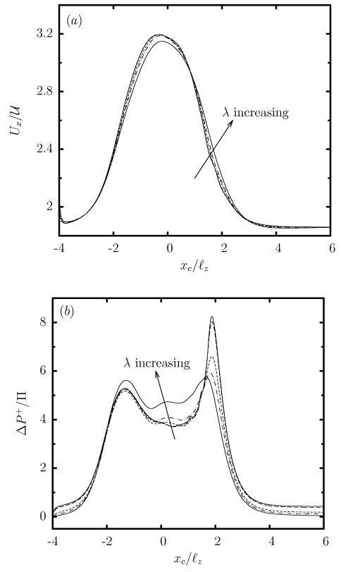
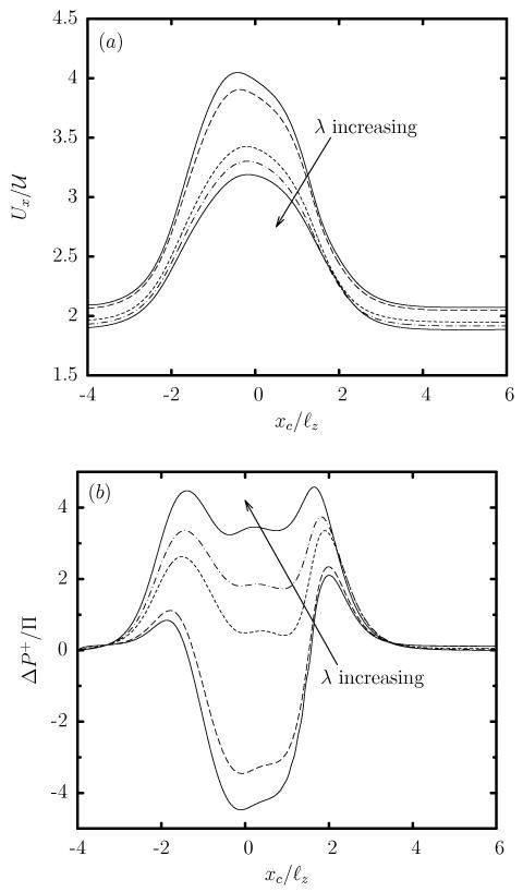
In contrast to the viscosity effects on the capsule deformation, the capsule velocity Ux is practically not affected by λ, and thus all capsules show the same increase in Ux as they pass through the constriction, as seen in figure 7(a). Similarly, the viscosity ratio has very weak effects on the additional pressure difference ΔP+ which is positive for all viscosity ratios (even for inviscid capsules with λ << 1), as shown in figure 7(b).
FIG. 7.
Evolution of (a) the capsule velocity Ux, and (b) the additional pressure difference ΔP+, as a function of the centroid xc, for a Skalak capsule with C = 1, a/ℓz = 0.9 and Ca = 0.1, for viscosity ratio λ = 0.01, 0.1, 1, 2, 5.
A. Comparison with droplet dynamics
Owing to the rather unexpected behavior of the capsule velocity Ux and the additional pressure difference ΔP+ not to be affected much by the viscosity ratio, we proceed now by investigating the corresponding effects on the droplet deformation. A droplet is also a deformable object but, in contrast to a capsule, its surface tension γ remains constant. Thus, our goal here is to clarify the similarities and differences of droplet and capsule transient dynamics as they pass through the microfluidic constriction. To determine the droplet dynamics, we utilized our fully-implicit time-integration spectral algorithm for droplets [12] as well as our membrane spectral boundary element algorithm by imposing surface-tension interfacial conditions, which is identical to our explicit time-integration spectral algorithm for droplets [46]. In this case, the capillary number is defined as where γ is the droplet’s surface tension.
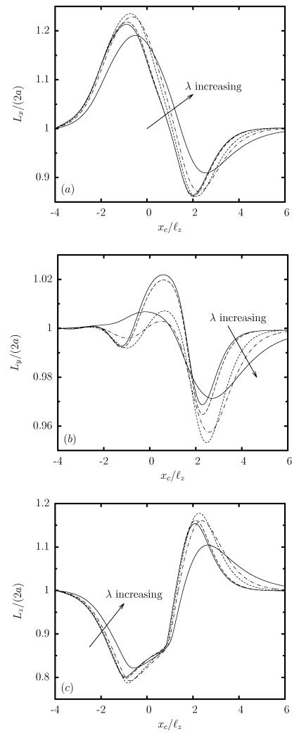
A comparison of the deformation of droplets and capsules, as in figures 8 and 6, reveals that the droplet’s length Lx and height Lz deform similarly to those for a capsule, as both soft particles pass through the microfluidic constriction. It is of interest to note that similar interfacial deformation was also found, both computationally and experimentally, for nearly-spherical vesicles in microchannels with oscillating height [6, 29]. In essence, the deformation of the particle’s length and height is a pure hydrodynamic effect due to the significant changes in the flow caused by the constriction.
FIG. 8.
Evolution of the droplet lengths as a function of the centroid xc, for a droplet with a/ℓz = 0.9, Ca = 0.1 and viscosity ratio λ = 0.01, 0.1, 1, 2, 5. (a) Length Lx, (b) width Ly, and (c) height Lz (scaled with the length 2a of the undisturbed spherical shape). Our results for λ = 0.01 are identical for lower viscosity ratios, e.g. λ = 0.001, 0, and thus represent the low-viscosity limit λ << 1.
On the other hand, the droplet’s lateral dimension (i.e. its width Ly) shows a smaller deformation than that for a capsule. Furthermore, the width Ly of the droplet increases only during the confinement area where the droplet enters the constriction, and decreases during the expansion area where the droplet exits the constriction, while the capsule remains laterally elongated over the entire constriction. The different evolution of the width of the two soft particles in the rectangular constriction is similar to the difference in the steady-state shapes of droplets and capsules in rectangular channels identified in our recent work [23]. In particular, in asymmetric channel flows, a capsule extends significantly along the less-confined lateral direction of the channel cross-section (i.e. the channel width) to facilitate the development of strong lateral tensions required for interfacial stability. Such deformation is not required for a droplet owing to its a constant surface tension, and thus in the present problem, the droplet width, after the initial increase in the confinement area, reduces in the expansion area to facilitate the flattened parachute shape as the droplet exits the constriction.
The major differences in the motion of the two soft particles involve the velocity Ux and the additional pressure difference ΔP+, which in the case of a droplet are affected significantly by the viscosity ratio λ as shown in figure 9. In contrast to the practically insensitive capsules, the velocity of a droplet decreases with the viscosity ratio. The same is true for its additional pressure difference ΔP+ which for a droplet is negative for low enough viscosity ratios. It is of interest to note that the evolution of the velocity Ux and the additional pressure difference ΔP+ for a very viscous droplet (e.g. λ = 5) is very similar to that for the capsule (at any viscosity ratio). Therefore, even under the transient conditions imposed by the microfluidic constriction, capsules with any viscosity ratio correspond better to very viscous droplets, as we identified for steady-state capsule motion in solid ducts [22].
FIG. 9.
Evolution of (a) the velocity Ux, and (b) the additional pressure difference ΔP+, as a function of the centroid xc, for a droplet with a/ℓz = 0.9, Ca = 0.1 and viscosity ratio λ = 0.01, 0.1, 1, 2, 5.
B. Reasoning for the transient dynamics of droplets and capsules
To explain the different effects of the viscosity ratio on the transient velocity Ux and the additional pressure difference ΔP+ of droplets and capsules over the constriction, we need to consider the fluid circulation inside the soft particles.
For the case of droplets, where the interface is just a separation of two fluid phases with no material, there may be a significant inner circulation (with respect to the translation motion) owing to the continuity of the interfacial shear stresses from the surrounding and inner fluids. Thus, complex streamline patterns have been found for steady-state droplet motion in solid ducts; for example, see figure 3 in Ref.[20] and figure 3(a) in Ref.[24]. The same is true for unsteady droplet motion such as its passing through the microfluidic constriction studied in this work. For low-viscosity ratio, the inner circulation is as significant as the droplet translation velocity Ux. This is shown for λ ≤ 0.1 in table 2, where we calculated the maximum and average of the absolute value of the interfacial shear velocity (with respect to the droplet translation velocity Ux) as the capsule passes through the constriction. Note that the magnitude of the interfacial shear velocity represents very well the strength of the inner circulation. As the viscosity ratio increases, the inner circulation becomes weaker, e.g. its representative velocity is reduced compared to the droplet translation velocity Ux, as seen in table 2 for λ = 1, 2. For very viscous droplets, the inner circulation becomes negligible (as shown in table 2 for λ = 5), and eventually for λ → ∞ the droplet solidifies, the inner circulation becomes zero and the entire droplet moves with its translation velocity Ux only.
TABLE 2.
Maximum and average of the absolute value of the shear velocity on the surface of a droplet or capsule (in the reference frame moving with the soft particle), when the particle is in the middle of the constriction (i.e. xc ≈ 0), for a/ℓz = 0.9, Ca = 0.1 and several viscosity ratios λ. Also included is the particle velocity Ux for comparison reasons. (The velocity scale is the average undisturbed velocity in the square channel.) Similar results we obtain when the capsule enters or exits the constriction.
| Maximum interfacial shear velocity | |||||
|---|---|---|---|---|---|
| Particle | λ | Ux | |ux|max | |uy|max | |uz|max |
|
| |||||
| 0.01 | 3.968 | 3.264 | 0.476 | 0.943 | |
| 0.1 | 3.852 | 2.952 | 0.408 | 0.860 | |
| Droplet | 1 | 3.411 | 1.620 | 0.177 | 0.454 |
| 2 | 3.291 | 1.129 | 0.194 | 0.301 | |
| 5 | 3.181 | 0.660 | 0.156 | 0.177 | |
|
| |||||
| 0.01 | 3.175 | 0.197 | 0.160 | 0.262 | |
| 0.1 | 3.175 | 0.192 | 0.156 | 0.253 | |
| Capsule | 1 | 3.167 | 0.152 | 0.123 | 0.201 |
| 2 | 3.165 | 0.140 | 0.100 | 0.160 | |
| 5 | 3.138 | 0.102 | 0.068 | 0.101 | |
| Average interfacial shear velocity | |||||
|---|---|---|---|---|---|
| Particle | λ | Ux | |ux|ave | |uy|ave | |Uz|ave |
|
| |||||
| 0.01 | 3.968 | 1.335 | 0.294 | 0.336 | |
| 0.1 | 3.852 | 1.161 | 0.237 | 0.302 | |
| Droplet | 1 | 3.411 | 0.516 | 0.070 | 0.150 |
| 2 | 3.291 | 0.344 | 0.046 | 0.102 | |
| 5 | 3.181 | 0.185 | 0.028 | 0.059 | |
|
| |||||
| 0.01 | 3.175 | 0.108 | 0.034 | 0.084 | |
| 0.1 | 3.175 | 0.106 | 0.033 | 0.082 | |
| Capsule | 1 | 3.167 | 0.093 | 0.027 | 0.070 |
| 2 | 3.165 | 0.083 | 0.022 | 0.059 | |
| 5 | 3.138 | 0.060 | 0.015 | 0.041 | |
For the case of capsule motion in solid ducts, at steady state there is no flow inside the capsule owing to the specific symmetry of the channel flow and the material interface, i.e. the elastic-solid membrane [22, 32]. Thus, the steady-state capsule motion in duct flows corresponds better to the dynamics of high-viscosity (λ >> 1) droplets since at steady state both soft particles translate in the duct flow as solids with zero inner velocity, as discussed in our earlier papers [22, 23].
During transient, non-tank-treading capsule motion, as in the current problem, the deformation of the capsule should create some inner circulation. To determine how significant this inner motion is, in table 2 we also include information on the magnitude of the interfacial shear velocity (with respect to the translation velocity Ux) for capsules inside the constriction with several viscosity ratios. In contrast to droplets, the circulation inside a capsule passing through the constriction remains always small (compared to its translation velocity Ux), even at low viscosity ratios.
Therefore, owing to restrictions imposed by the material membrane, the transient, non-tank-treading capsule deformation is always accompanied with a weak inner circulation, and thus the viscosity ratio does not affect much the capsule velocity Ux and the additional pressure difference ΔP+, as shown earlier in figure 7. In addition, the weak inner circulation results in a positive additional pressure difference ΔP+ even for low-viscosity capsules with λ << 1, in direct contrast to low-viscosity droplets which create a negative ΔP+. In essence, owing to the weak inner circulation, during transient, non-tank-treading motion, capsules at any viscosity ratio still correspond to high-viscosity (λ >> 1) droplets, as at steady state [22, 23].
It is of interest to note that low-viscosity capsules are more deformed than very viscous capsules as discussed earlier around Eq.(6), and thus they show a more flattened parachute shape as they exit the constriction, characterized by a higher height Lz as seen in figure 6(c) for xc/ℓz ≈ 2. The larger flow blocking of the more deformed shapes causes a higher peak in the positive additional pressure difference ΔP+ of low-viscosity capsules in the expansion area, shown in figure 9(b) for xc/ℓz ≈ 2.
5. CONCLUSIONS
In this paper we have investigated computationally the transient dynamics of an elastic capsule flowing along the centerline of a square microchannel with a rectangular constriction in the middle. In particular, we have considered a slightly over-inflated elastic capsule made of a strain-hardening membrane (following the Skalak et al. constitutive law) with comparable shearing and areadilatation resistance. Our investigation involves low-to-moderate flow rates with capillary number Ca = O(0.1) and capsule sizes a comparable or smaller to the constriction narrowest direction (height). This study is motivated by a wide range of applications including drug delivery, cell sorting and cell characterization devices, microcapsule fabrication, determination of membrane properties, and of course its similarity to blood flow in vascular capillaries.
Our computational investigation reveals that the capsule shows a rich deformation behavior as it moves inside the microfluidic device. In particular, the two distinct regimes associated with the microfluidic constriction, i.e. confinement and expansion, result in two distinct interfacial shapes. In the confinement regime, the capsule obtains an elongated shape with a maximum length and a minimum height. The opposite happens during the expansion dynamics where the capsule obtains a flattened parachute shape. The deformation of the capsule’s length and height is a pure hydrodynamic effect due to the significant changes in the flow caused by the constriction, and thus it is similar to that for a droplet or a vesicle [6, 29]. However, over the entire passing through the rectangular constriction, the capsule shows an elongated width owing to the development of strong lateral tensions on the capsule membrane required for interfacial stability in asymmetric channels as discussed in our recent work [23]. Therefore, the transient capsule motion is associated with a highly non-axisymmetric, fully three-dimensional capsule shape which cannot be described from single-view observations as commonly happens in microfluidic experiments or based on axisymmetric or two-dimensional computations.
As the capsule size increases (or as the flow rate decreases), the gap between the capsule surface and the solid walls decreases, and thus the capsule velocity decreases while the additional pressure difference increases. Thus, larger capsules take more time to pass the constriction and cause higher additional pressure difference, owing to higher flow blocking.
Our work highlights the effects of two different mechanisms for capsule’s non-tank-treading transient dynamics. The capsule deformation results from the combined effects of the surrounding and inner fluids’ normal stresses on the soft particle’s interface, and thus when the capsule viscosity increases, its transient deformation decreases, as for droplets. However, the capsule deformation is not able to create a strong enough inner circulation (owing to restrictions imposed by the material membrane), and thus the viscosity ratio does not affect much the capsule velocity and the additional pressure difference. In addition, the weak inner circulation results in a positive additional pressure difference even for low-viscosity capsules. This is in direct contrast to low-viscosity droplets where the continuity of the interfacial shear stresses from the surrounding and inner fluids creates a strong inner circulation and a negative additional pressure difference. In essence, owing to the weak inner circulation, during transient non-tank-treading motion, capsules at any viscosity ratio λ correspond to high-viscosity (λ >> 1) droplets, as at steady state where there is no flow inside the capsules [22, 23].
It is of interest to note that our conclusions are not restricted to artificial capsules but should also represent physiological capsules, such as erythrocytes, for the same physical reasons. The erythrocyte membrane consists of an outer lipid bilayer (which is essentially a two-dimensional incompressible fluid with no shearing resistance as in vesicles) and an underlying spectrin skeleton (which exhibits shearing and area-dilatation resistance like the elastic membrane of common artificial capsules) [41]. Under different flow conditions, the spectrin cytoskeleton dominates the erythrocyte dynamics and the cell behaves like a non-spherical capsule [15, 42]. The erythrocyte is responsible for exchanging oxygen and carbon dioxide with the tissues in the vascular capillaries [31]. The cell’s interior is a concentrated solution of the protein hemoglobin which binds oxygen in the pulmonary system, and releases it to the tissues throughout the systemic circulation. Because of hemoglobin, the cytoplasm viscosity is several times higher than the plasma viscosity resulting in a viscosity ratio λ ≈ 5 at the human body temperature of 37° [28, 41]. Our work suggests that the much higher cytoplasmatic viscosity does not affect adversely the velocity of non-tank-trading erythrocytes in vascular capillaries nor impose any additional energy requirement for the cells flow since it does not affect much the additional pressure difference.
ACKNOWLEDGMENTS
This work was supported in part by the National Science Foundation and the National Institutes of Health. Most computations were performed on multiprocessor computers provided by the Extreme Science and Engineering Discovery Environment (XSEDE) which is supported by the National Science Foundation.
Appendix: Time scale analysis for the interfacial dynamics of capsules
The dynamics of elastic capsules with shearing and area-dilatation resistance evolves on the membrane tension time scale, which at the small deformation regime was found to be
| (7) |
(where Es is the membrane’s Young modulus), by the analytical investigations of Brunn [7] and of Barthès-Biesel and Rallison [5]. Note that the analytical investigations showed that the dynamics of a capsule with a thin elastic membrane should be affected by two time scales (differed by a factor of O(10)) owing to the two associated deformation modes, i.e. overall shape and in-surface stretching. In evolution or relaxation experiments, after the very early times, only the larger time scale (i.e. the one with the minus in the denominator) affects the dynamics, being the dominant one in the transient process [5, 7].
The viscosity ratio term shown in Eq.(7) appears to be complicated but for both time scales, it can be represented very well by a simple linear increase with λ, e.g.
| (8) |
(where the relative error of the linear approximation is less than 10−2). We emphasize that the membrane time scale τm in this equation is similar to the droplet time scale
| (9) |
found by the early analytical investigation of Taylor [43]. (See also section 4 in the review article by Rallison [34].)
This reveals that both time scales result from the common physics of the two-phase interfacial dynamics, i.e. the combined effects of the surrounding and inner hydrodynamics on the soft particles’ interface, as shown at the interfacial stress condition Eq.(1). Note that in this equation, the surface stress vector (or hydrostatic traction) Δf is defined from the stress tensor σ and the interfacial unit normal n pointing into the surrounding fluid, i.e.
| (10) |
where the subscripts 1 and 2 represent the particle’s inner and surrounding fluids, respectively. Observe that in Eq.(10) the minus sign shows in reality additive contribution of the surrounding and inner fluids’ stresses on the interface owing to the stress definition to represent the force from the upper to the lower fluid layer along the direction of the surface’s normal vector.
For a strain-hardening Skalak capsule, the Young modulus is related to the membrane’s shear and area-dilatation moduli by Es = 2 Gs (1 + 2C)/(1 + C) [32], and thus for the Skalak C = 1 capsules studied in this work, Es = 3 Gs. Utilizing the dimensionless parameters valid for the current work, the membrane time scale becomes
| (11) |
where is the flow time scale and the capillary number contains the membrane’s shear modulus Gs. Therefore, excluding the numerical coefficients associated with the viscosity ratio, which are of O(1), the membrane time scale for microfluidic flows can be expressed as
| (12) |
For non-small capsule deformations in microfluidic flows, such as the ones studied in the present paper or in our earlier investigations for capsule motion in square or rectangular microchannels [22, 23], our computational results show that the capsule dynamics is well represented by the membrane time scale given by Eq.(12).
References
- [1].Abkarian M, Faivre M, Horton R, Smistrup K, Best-Popescu CA, Stone HA. Cellular-scale hydrodynamics. Biomed. Mater. 2008;3:034011. doi: 10.1088/1748-6041/3/3/034011. 1-13. [DOI] [PubMed] [Google Scholar]
- [2].Alexeev A, Balazs AC. Designing smart systems to selectively entrap and burst microcapsules. Soft Matter. 2007;3:1500–1505. doi: 10.1039/b711769h. [DOI] [PubMed] [Google Scholar]
- [3].Antia M, Herricks T, Rathod PK. Microfluidic modeling of cell-cell interactions in malaria pathogenesis. PLoS Pathog. 2007;3:0939–0948. doi: 10.1371/journal.ppat.0030099. [DOI] [PMC free article] [PubMed] [Google Scholar]
- [4].Baroud CN, Gallaire F, Dangla R. Dynamics of microfluidic droplets. Lap Chip. 2010;10:2032–2045. doi: 10.1039/c001191f. [DOI] [PubMed] [Google Scholar]
- [5].Barthès-Biesel D, Rallison JM. The time-dependent deformation of a capsule freely suspended in a linear shear flow. J. Fluid Mech. 1981;113:251–267. [Google Scholar]
- [6].Braunmüller S, Schmid L, Franke T. Dynamics of red blood cells and vesicles in microchannels of oscillating width. J. Phys.: Condens. Matter. 2011;23:184116. doi: 10.1088/0953-8984/23/18/184116. [DOI] [PubMed] [Google Scholar]
- [7].Brunn P. On the rheology of viscous drops surrounded by an elastic shell. Biorheology. 1980;17:419–430. [PubMed] [Google Scholar]
- [8].Chabert M, Viovy J-L. Microfluidic high-throughput encapsulation and hydrodynamic self-sorting of single cells. Proc. Natl. Acad. Sci. 2008;105:3191–3196. doi: 10.1073/pnas.0708321105. [DOI] [PMC free article] [PubMed] [Google Scholar]
- [9].Chen W, Yang Y, Rinadi C, Zhou D, Shen AQ. Formation of supramolecular hydrogel microspheres via microfluidics. Lab Chip. 2009;9:2947–2951. doi: 10.1039/b906254h. [DOI] [PubMed] [Google Scholar]
- [10].Coupier G, Farutin A, Minetti C, Podgorski T, Misbah C. Shape Diagram of Vesicles in Poiseuille Flow. Phys. Rev. Lett. 2012;108:178106. doi: 10.1103/PhysRevLett.108.178106. [DOI] [PubMed] [Google Scholar]
- [11].Cranston HA, Boylan CW, Carroll GL, Sutera SP, Williamson JR, Gluzman IY, Krogstad DJ. Plasmodium falciparum maturation abolishes physiologic red cell deformability. Science. 1984;223:400–403. doi: 10.1126/science.6362007. [DOI] [PubMed] [Google Scholar]
- [12].Dimitrakopoulos P. Interfacial dynamics in Stokes flow via a three-dimensional fully-implicit interfacial spectral boundary element algorithm. J. Comp. Phys. 2007;225:408–426. [Google Scholar]
- [13].Dimitrakopoulos P. Analysis of the variation in the determination of the shear modulus of the erythrocyte membrane: effects of the constitutive law and membrane modeling. Phys. Rev. E. 2012;85:041917. doi: 10.1103/PhysRevE.85.041917. [DOI] [PMC free article] [PubMed] [Google Scholar]
- [14].Dodson WR, III, Dimitrakopoulos P. Dynamics of strain-hardening and strain-softening capsules in strong planar extensional flows via an interfacial spectral boundary element algorithm for elastic membranes. J. Fluid Mech. 2009;641:263–296. [Google Scholar]
- [15].Dodson WR, III, Dimitrakopoulos P. Tank-treading of erythrocytes in strong shear flows via a non-sti cytoskeleton-based continuum computational modeling. Biophys. J. 2010;99:2906–2916. doi: 10.1016/j.bpj.2010.08.048. [DOI] [PMC free article] [PubMed] [Google Scholar]
- [16].Fedosov DA, Lei H, Caswell B, Suresh S, Karniadakis GE. Multiscale modeling of red blood cell mechanics and blood flow in malaria. PLoS Comput. Biol. 2011;7:e1002270. doi: 10.1371/journal.pcbi.1002270. [DOI] [PMC free article] [PubMed] [Google Scholar]
- [17].Fiddes LK, Young EWK, Kumacheva E, Wheeler AR. Flow of microgel capsules through topographically patterned microchannels. Lab Chip. 2007;7:863–867. doi: 10.1039/b703297h. [DOI] [PubMed] [Google Scholar]
- [18].Gaver DP, Kute S. A theoretical model study of the influence of fluid stresses on a cell adhering to a microchannel wall. Biophys. J. 1998;75:721–733. doi: 10.1016/S0006-3495(98)77562-9. [DOI] [PMC free article] [PubMed] [Google Scholar]
- [19].Hénon S, Lenormand G, Richert A, Gallet F. A new determination of the shear modulus of the human erythrocyte membrane using optical tweezers. Biophys. J. 1999;76:1145–1151. doi: 10.1016/S0006-3495(99)77279-6. [DOI] [PMC free article] [PubMed] [Google Scholar]
- [20].Ho BP, Leal LG. The creeping motion of liquid drops through a circular tube of comparable diameter. J. Fluid Mech. 1975;71:361–383. [Google Scholar]
- [21].Jiang K, Thomas PC, Forry SP, DeVoe DL, Raghavan SR. Microfluidic synthesis of monodisperse PDMS microbeads as discrete oxygen sensors. Soft Matter. 2012;8:923–926. [Google Scholar]
- [22].Kuriakose S, Dimitrakopoulos P. Motion of an elastic capsule in a square microfluidic channel. Phys. Rev. E. 2011;84:011906. doi: 10.1103/PhysRevE.84.011906. [DOI] [PMC free article] [PubMed] [Google Scholar]
- [23].Kuriakose S, Dimitrakopoulos P. Deformation of an elastic capsule in a rectangular microfluidic channel. Soft Matter. 2013;9:4284–4296. doi: 10.1039/C3SM27683J. [DOI] [PMC free article] [PubMed] [Google Scholar]
- [24].Lac E, Sherwood JD. Motion of a drop along the centreline of a capillary in a pressure-driven flow. J. Fluid Mech. 2009;10:27–54. [Google Scholar]
- [25].Leclerc E, Kinoshita H, Fujii T, Barthès-Biesel D. Transient flow of microcapsules through convergent-divergent microchannels. Microfluid Nanofluid. 2012;12:761–770. [Google Scholar]
- [26].Lensen D, Breukelen KV, Vriezema DM, Hest JCMV. Preparation of biodegradable liquid core PLLA microcapsules and hollow PLLA microcapsules using microfluidics. Macromol. Biosci. 2010;10:475–480. doi: 10.1002/mabi.200900404. [DOI] [PubMed] [Google Scholar]
- [27].McWhirter JL, Noguchi H, Gompper G. Flow-induced clustering and alignment of vesicles and red blood cells in microcapillaries. PNAS. 2009;106:6039–6043. doi: 10.1073/pnas.0811484106. [DOI] [PMC free article] [PubMed] [Google Scholar]
- [28].Mohandas N, Chasis JA. Red blood cell deformability, membrane material properties and shape: regulation by transmembrane, skeletal and cytosolic proteins and lipids. Sem. Hem. 1993;30:171–192. [PubMed] [Google Scholar]
- [29].Noguchi H, Gompper G, Schmid L, Wixforth A, Franke T. Dynamics of fluid vesicles in flow through structured microchannels. Europhys. Lett. 2010;89:28002. [Google Scholar]
- [30].Olbricht WL, Leal LG. The creeping motion of immiscible drops through a converging/diverging tube. J. Fluid Mech. 1983;134:329–355. [Google Scholar]
- [31].Popel AS, Johnson PC. Microcirculation and Hemorheology. Annu. Rev. Fluid Mech. 2005;37:43–69. doi: 10.1146/annurev.fluid.37.042604.133933. [DOI] [PMC free article] [PubMed] [Google Scholar]
- [32].Pozrikidis C, editor. Modeling and Simulation of Capsules and Biological Cells. Chapman and Hall; London: 2003. [Google Scholar]
- [33].Prevot M, Cordeiro AL, Sukhorukov GB, Lvov Y, Besser RS, Möhwald H. Design of a microfluidic system to investigate the mechanical properties of layer-by-layer fabricated capsules. Macromol. Mater. Eng. 2003;288:915–919. [Google Scholar]
- [34].Rallison JM. The deformation of small viscous drops and bubbles in shear flows. Ann. Rev. Fluid Mech. 1984;16:45–66. [Google Scholar]
- [35].Quéguiner C, Barthès-Biesel D. Axisymmetric motion of capsules through cylindrical channels. J. Fluid Mech. 1997;348:349–376. [Google Scholar]
- [36].Risso F, Collé-Pailot F, Zagzoule M. Experimental investigation of a bioartificial capsule flowing in a narrow tube. J. Fluid Mech. 2006;547:149–173. [Google Scholar]
- [37].Sei ert S, Thiele J, Abate AR, Weitz DA. Smart microgel capsules from macromolecular precursors. J. Am. Chem. Soc. 2010;132:6606–6609. doi: 10.1021/ja102156h. [DOI] [PubMed] [Google Scholar]
- [38].Sugihara-Seki M, Schmid-Schönbein GW. The fluid shear stress distribution on the membrane of leukocytes in the microcirculation. J. Biomech. Eng. 2003;125:628–638. doi: 10.1115/1.1611515. [DOI] [PubMed] [Google Scholar]
- [39].Shelby JP, White J, Ganesan K, Rathod PK, Chiu DT. A microfluidic model for single-cell capillary obstruction by Plasmodium falciparum infected erythrocytes. Proc. Natl. Acad. Sci. USA. 2003;100:14618–14622. doi: 10.1073/pnas.2433968100. [DOI] [PMC free article] [PubMed] [Google Scholar]
- [40].Skalak R, Tozeren A, Zarda RP, Chien S. Strain energy function of red blood cell membranes. Biophys. J. 1973;13:245–264. doi: 10.1016/S0006-3495(73)85983-1. [DOI] [PMC free article] [PubMed] [Google Scholar]
- [41].Skalak R, Özkaya N, Skalak TC. Biofluid Mechanics. Annu. Rev. Fluid Mech. 1989;21:167–204. [Google Scholar]
- [42].Skotheim JM, Secomb TW. Red blood cells and other nonspherical capsules in shear flow: oscillatory dynamics and the tank-treading-to-tumbling transition. Phys. Rev. Lett. 2007;98:078301. doi: 10.1103/PhysRevLett.98.078301. [DOI] [PubMed] [Google Scholar]
- [43].Taylor GI. The viscosity of a fluid containing small drops of another fluid. Proc. Roy. Soc. A. 1932;138:41–48. [Google Scholar]
- [44].Wang Y, Dimitrakopoulos P. Normal force exerted on vascular endothelial cells. Phys. Rev. Lett. 2006;96:028106. doi: 10.1103/PhysRevLett.96.028106. 1-4. [DOI] [PubMed] [Google Scholar]
- [45].Wang Y, Dimitrakopoulos P. Nature of the hemodynamic forces exerted on vascular endothelial cells or leukocytes adhering to the surface of blood vessels. Phys. Fluids. 2006;18:087107. 1-14. [Google Scholar]
- [46].Wang Y, Dimitrakopoulos P. A three-dimensional spectral boundary element algorithm for interfacial dynamics in Stokes flow. Phys. Fluids. 2006;18:082106. 1-16. [Google Scholar]


