

Abstract
Inhalational anaesthetic agents are usually liquids at room temperature and barometric pressure and need to be converted to vapour before being used and this conversion is effected using a vapouriser. Vapourisers have evolved from very basic devices to more complicated ones. Anaesthetists should understand the basic principles of anaesthetic vapouriser, including the principles that affect vapouriser output and how they influence vapouriser design. Most of the modern vapourisers in use are designed to be used between the flow meter and the common gas outlet on the anaesthesia machine. Modern vapourisers are flow and temperature compensated, concentration calibrated, direct reading, dial controlled and are unaffected by positive-pressure ventilation. Safety features include an anti-spill and a select-a-tec mechanism and a specific vapouriser filling device. Desflurane has unique physical properties requiring the use of a specific desflurane vapouriser. The most recently designed vapourisers are controlled by a central processing unit in the anaesthetic machine. The concentration of vapour is continuously monitored and adjusted by altering fresh gas flow through the vapouriser. This article looks at the basic design and functioning of the modern vapourisers.
Keywords: Aladin cassettes, desflurane vapouriser, direct injection of volatile anesthetic, measured flow vapouriser, plenum vapouriser
INTRODUCTION
Anaesthetic vapourisers, used for the administration of volatile anaesthetics, have evolved from the simple masks used for open ether anaesthesia to the present day modern electronically controlled vapourisers designed to deliver potent modern inhalation aesthetic agents. An anaesthetic vapouriser must deliver a safe, reliable concentration of volatile agent to the patient. The safe delivery of volatile anaesthesia today is due in part to the development of increasingly advanced vapourisers. The characteristics of the modern vapourisers with their special construction and operation are discussed below.
The American society for testing and materials anaesthesia workstation standard[1] contains the following provisions regarding vapourisers:
The effects of variations in ambient temperature and pressure, tilting, back pressure and input flow rate and gas mixture composition on vapouriser performance must be stated in the accompanying documents.
The average delivered concentration from the vapouriser shall not deviate from the set value by more than ±20% or ±5% of the maximum setting, whichever is greater, without back pressure.
The average delivered concentration from the vapouriser shall not deviate from the set value by more than +30% or −20% or by more than +7.5% or −5% of the maximum setting, whichever is greater, with pressure fluctuations at the common gas outlet of 2 kPa with a total gas flow of 2 L/min or 5 kPa with a total gas flow of 8 L/min.
A system that prevents gas from passing through the vapourising chamber or reservoir of one vapouriser and then through that of another must be provided.
The output of the vapouriser shall be less than 0.05% in the “OFF” or “zero” position if the “zero” position is also the “OFF” position.
All vapouriser control knobs must open counter clockwise.
Either the maximum and minimum filling levels or the actual usable volume and capacity shall be displayed.
The vapouriser must be designed so that it cannot be overfilled when in the normal operating position.
Vapourisers unsuitable for use in the breathing system must have non-interchangeable proprietary or 23-mm fittings. Conical fittings of 15 mm and 22 mm cannot be used. When 23-mm fittings are used, the inlet of the vapouriser must be male and the outlet female. The direction of gas flow must be marked.
Vapourisers suitable for use in the breathing system must have standard 22-mm fittings or screw-threaded, weight-bearing fittings with the inlet female and the outlet male. The direction of gas flow must be indicated by arrows and the vapouriser marked “for use in the breathing system.”
CLASSIFICATION OF MODERN VAPOURISERS
The purpose of a modern vapouriser is to reliably deliver an accurate, adjustable concentration of anaesthetic vapour for the purpose of inhalational anaesthesia. In order to give clinically useful concentrations of the agent, the anaesthetic vapour has to be diluted with fresh gas in one of the two ways:[2,3]
By splitting the fresh gas flow so that only a portion passes through the vapourising chamber and the rest bypasses it – variable bypass vapourisers.
By injecting the vapour directly to the total fresh gas flow without any split – measured flow vapourisers.
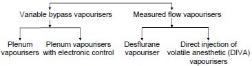
Variable bypass vapourisers: Can be classified into
-
Plenum vapourisers: For halothane, enflurane, isoflurane, sevoflurane except desflurane.
Examples: (i) Tec 5 and 7 vaporizers® (GE) (ii) Vapor 2000® series (Drager) (iii) Sigma Delta® (Penlon).
-
Plenum vapourisers with electronic control: For halothane, enflurane, isoflurane, sevoflurane and desflurane.
Example: Aladin cassette vaporizer® (GE).
Measured flow vapourisers: Can be classified into
-
Desflurane Vapouriser: Only for desflurane.
Examples: (i) Tec 6® (GE) (ii) D vapor® (Drager) (iii) Sigma Alpha® (Penlon).
-
Direct injection of volatile anaesthetic vapouriser: For halothane, enflurane, isoflurane, sevoflurane and desflurane.
Examples: (i) The Drager DIVA® (ii) The Maquet 950® series.
Variable bypass vapourisers
Principle of plenum vapourisers
Examples: (i) Tec 5 and 7 vaporizers® (GE) [Figure 1a and b] (ii) Vapor 2000 Series® (Drager) [Figure 1c] (iii) Sigma Delta® (Penlon) [Figure 1d]. The working principle of all these vapourisers is similar.
Figure 1.
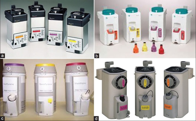
(a) Tec 5 vapouriser® (b) Tec 7 vapourisers® (GE) (c) Vapour 2000® (Drager) (d) Sigma Delta® (Penlon)
The term plenum is used to describe a pressurised chamber. In plenum vapourisers, the internal resistance is high requiring fresh gas flow above atmospheric pressure. These vapourisers are the most commonly used and are described as variable bypass, flow over, temperature compensated, concentration calibrated and agent specific vapourisers.
The concentration control dial setting determines the “splitting ratio,” that is the ratio of fresh gas flow which enters the vapourising chamber to that which bypasses the vapourising chamber. This variable bypass regulates the concentration of the anaesthetic agent. The part of the fresh gas which enters the vapourising chamber flows over the wicks and baffles to maximise the surface area of vapourisation. Thermo compensation is done by automatic devices to ensure a steady vapouriser output over a wide range of OR temperatures. These vapourisers are agent specific being calibrated for a specific gas and are used to deliver halothane, enflurane, isoflurane and sevoflurane, but not desflurane.
Mode of operation[2,4,5,6]
The fresh gas flow from the flow meters enters the vapouriser and is split into two streams, one stream flows into the fresh gas bypass circuit and the other stream flows through the vapourising chamber where it is enriched with the vapour of the liquid anaesthetic agent. The bypass circuit includes the gas transfer manifold and a thermostat assembly which is located at the base of the vapouriser. The fresh gas flows through the bypass circuit vertically downwards across the sump through the thermostats and back up the gas transfer manifold to the common gas outlet. The thermostat deflects according to its temperature to control the resistance offered to the flow of gas through it. This deflection varies the relative proportions of gas flowing through the bypass and vapourising chamber circuits [Figure 2].
Figure 2.

Principle of variable bypass vapouriser -plenum vapouriser
Vapourising chamber circuit: The fresh gas flow through the vapourising chamber flows from the flow meter across the sump cover where it is diverted through the central cavity of the rotary valve and back through the intermittent positive pressure ventilation (IPPV) compensating assembly. From the IPPV assembly gas flows through the tubular wick assembly where it picks up anaesthetic vapour and then flows across the base of the vapourising chamber above the liquid agent. From the base of the vapourising chamber, the gas/agent mixture flows through the sump cover to the proportional radial drug control groove of the rotary valve and then back into the sump cover where it combines with the fresh gas from the bypass circuit. The combined total flow then flows out from the vapouriser and via the selectatec circuitry to the anaesthesia gas delivery system.
Vapouriser components: Include the concentration control dial, the bypass chamber, the vapourising chamber, the filler port and filler cap. The vapouriser chamber is filled with liquid anaesthetic through the filler port. The maximum safe level is predetermined by the position of the filler port, which is positioned to minimise the chance of overfilling. The concentration control dial is a variable restrictor and may be located either in the bypass chamber or in the outlet of the vapourising chamber and regulates the relative flow rates through the bypass and vapourising chambers. Approximately, 80% of the flow passes through the bypass chamber to the vapouriser outlet while the remaining 20% flows through the vapourising chamber and entrains a specific flow of inhaled anaesthetic. The final concentration of inhaled anaesthetic is the ratio of the inhaled anaesthetic to the total gas flow.
The Tec 7®[7] vapouriser is agent specific, temperature, flow and pressure compensated. The vapouriser is designed to be used on the selectatec series mounted manifold. It has a single control dial with a concentration scale calibrated in percentage of anaesthetic agent vapour per total volume (%v/v) for setting the desired concentration of the anaesthetic agent. With the vapouriser locking lever in the locked position, the dial release can be pressed in toward the dial to operate the interlock mechanism, which allows the manifold port valves to open, prevents an adjacent vapouriser from being turned on and allows the vapouriser to operate. Vapourisers for Sevoflurane are calibrated up to 8% and those for the other agents are calibrated up to 5%. A volume of 300 ml is required to fully charge a vapouriser with dry wicks of which 75 ml is retained by the wick system. A 5% vapouriser requires 170 ml and an 8% of vapouriser requires 137 ml to fill up from minimum to maximum mark. It offers a flow resistance of 10-15 cm water with vapouriser setting ON at a flow of 5l/min of oxygen at 21 ± 2°C.
Principle of plenum vapourisers with electronic control
Examples: (i) Aladin cassette vapouriser® (GE) [Figure 3a].
Figure 3.
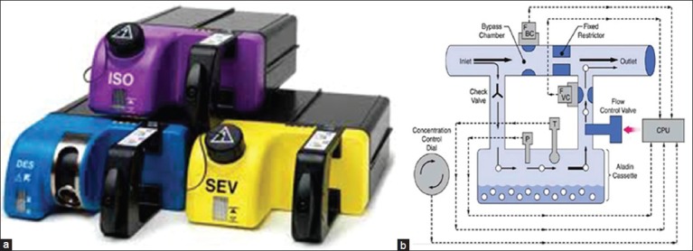
(a) Aladin cassettes® (GE) (b) Principle of plenum vapouriser with electronic control (Aladin vapouriser)
Aladin cassette vapourisers regulate anaesthetic vapour concentration with electro pneumatic proportional flow valves, controlled by microprocessors. This vapouriser is used in anaesthesia delivery unit and Aisys anaesthesia workstations of GE health-care. Though very different in external appearance, they are functionally similar to conventional vapourisers, with a bypass chamber and a vapourising chamber. A single electronic control system installed in the workstation can be used for all volatile anaesthetic agents including desflurane.
Mode of operation[2,4,5,6]
The vapouriser consists of two parts, an electronic control mechanism and the portable cassettes. The electronic control mechanism is in the anaesthesia machine. The agent is in a portable cassette that is inserted into a slot in the anaesthesia machine which recognises the contents of the cassette and dispenses agent into the stream of fresh gas flow. Each cassette is a liquid sump without control mechanisms and can be tipped and is maintenance free. The cassette and control mechanism are checked as a part of the electronic equipment checklist daily. It cannot deliver volatile agent in the absence of mains power, battery backup and adequate oxygen pressure. A handle on the front is used to carry the cassette and to insert it into and remove it from the machine. There is a release on the inside of the handle that when squeezed releases the cassette from the machine. It can be transported and stored in any position. The cassettes for halothane, enflurane and isoflurane have keyed fillers or the Easy-fil system. Sevoflurane cassettes may be equipped with either keyed filler or the Quik-fil system. The liquid level indicator and the filling port are located on the front. The cassette holds up to 250 ml when full. When the ball in the sight tube is at the bottom, the cassette contains 80 ml or less. The liquid level may also be displayed on the machine. When only 10% of liquid remains in the cassette, an alarm message appears. The agent concentration is adjusted by regulating the amount of fresh gas flowing through the cassette a proportional valve is used to regulate the flow. Part of the fresh gas bypasses the cassette so that the more fresh gas is allowed to pass through the cassette the greater the concentration. Fresh gas flows in and out of the cassette is electronically measured for enhanced control. When the cassette is removed, two spring-loaded valves automatically close the channels to and from the vapouriser. When the cassette is inserted into the machine, these valves open to make connections with the inflow and outflow channels. In error situations, the valves operate to cut-off anaesthetic agent delivery. A pressure relief opens to the scavenging line if a high pressure is detected in the cassette or the liquid level valve measuring device detects overfilling [Figure 3b].
Measured flow vapourisers
Principle of desflurane vapouriser
Examples: (i) Tec 6® (GE) [Figure 4a] (ii) D Vapor® (Drager) [Figure 4b] (iii) Sigma Alpha® (Penlon) [Figure 4c]. The working principle of all these vapourisers is similar.
Figure 4.

Desfurane Tec 6® (GE) (b) Desflurane D Vapor® (Drager) (c) Desflurane Sigma Alpha® (Penlon)
This vapouriser is meant to be used only for desflurane.[8,9] Desflurane has high volatility and low boiling point and this precludes its use with other conventional variable bypass vapourisers. As a result of this at 1 atmosphere and 20°C 100 ml/min of gas would entrain 735 ml/min of desflurane as against 46 ml/min of isoflurane and therefore to get an output of 1% the amount of bypass flow required would be approximately 73 L/min as against 5 L/min or less required for other anaesthetics. In addition, above 22.8°C at 1 atm desflurane boils and the amount of vapour produced is limited by the heat energy available from the vapouriser because of its specific heat. This in turn leads to excessive cooling of the vapouriser and reduces its output and hence that some form of external heat source is required.
The desflurane vapourisers are more precisely gas/vapour blenders. The vapouriser has two independent gas circuits arranged in parallel. Fresh gas from the flow meters enters the fresh gas inlet passes through a fixed restrictor and exits at the vapouriser's gas outlet. The vapour circuit originates at the desflurane sump, which serves as a reservoir of desflurane vapour. The sump is electrically heated and thermostatically controlled to 39°C. A shut off valve is positioned just downstream of the sump. Once the vapouriser has warmed up the shut off valve opens when the concentration control valve is in the on position. The concentration control vial is a variable restrictor, which controls the output of the vaporiser. A pressure regulating valve located downstream from the shut-off valve down regulates the pressure. The vapour flow and fresh gas flow are separated until they meet at a point downstream from the restrictors. The flows are interfaced pneumatically and electronically through differential pressure transducers, control electronics and a pressure regulating valve so that the working pressure of the vapouriser is proportional to the fresh gas flow [Figure 5].
Figure 5.
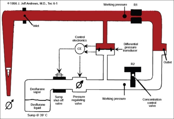
Principle of measured flow vapouriser (desflurane)
Principle of direct injection of volatile anaesthetic vapouriser
Examples: (i) The Drager DIVA® [Figure 6a] (ii) The Maquet 950 series® [Figure 6b].
Figure 6.
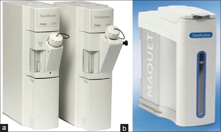
(a) The Drager DIVA® (b) The Maquet 950 series vapouriser®
The DIVA anaesthetic vapouriser is also a measured flow vapouriser but can be used for all modern inhalational anaesthetics including desflurane. The Drager DIVA® is a part of Drager Zeus anaesthesia workstation. It has two sections, a plug in vapourising module, which is specific for a particular agent and a built in gas supply module that is a part of the anaesthesia machine.
Mode of operation[2]
The vapourising module is agent specific and is connected to a storage tank. From the storage tank, the anaesthetic flows into the pump tank by gravity. When the pump tank is full it is pressurised by air from the workstation and the liquid anaesthetic agent is pushed into the metering tank. From the metering tank, the liquid anaesthetic passes through a fuel injector into a heated evaporation chamber where the saturated vapour of the liquid anaesthetic is produced. This vapour passes through a heated flow sensor into the patient gas circuit. All the tanks are connected by one-way valves to prevent back flow. These microprocessor controlled valves are linked to the flow sensor to regulate the volume of anaesthetic agent delivered.
![]()
The Maquet 950® series injection vapouriser[5] is used with the Maquet Flow i anaesthesia delivery system. The lightweight electronic injection vapourisers are placed centrally on the Flow-i. Switch between agents is performed by a touch on the intuitive display. The vapourisers can be refilled while still slotted in the machine and with one still in use. They are checked during the system checkout, which means no need for calibration. The desflurane vapouriser does not need to be heated up before use.
SAFETY FEATURES
Newer generations of anaesthesia vapourisers have built in safety features that have minimised or eliminated many hazards once associated with variable bypass vapourisers. Important safety features include:[5,6]
Keyed fillers which prevent filling the vapourisers with the wrong agent.
Low filling port which minimise overfilling of vapourisers.
Secured vapourisers minimise movement and thereby minimise tipping.
Interlocks prevent administration of more than one inhaled anaesthetic simultaneously.
Concentration dial increases output in all when rotated counter clockwise.
HAZARDS
Inspite of several safety features there are several hazards associated with vapourisers, which the Anaesthesiologist must be aware of:
Incorrect agent: While most common in vapourisers not equipped with keyed fillers, it may be possible to misfill vapourisers with keyed fillers in which case anaesthetic underdose or overdose can occur. The use of an agent monitor can protect against such an eventuality.
Tipping: If tipped more than 45° from the vertical, the liquid agent can obstruct valves and result in delivery of extremely high anaesthetic concentrations due to the flow of liquid anaesthetic into the bypass chamber. Such a situation may arise when the vapouriser is being moved. The treatment consists of flushing for 20-30 min at high flow rates with the vapouriser control dial being set at low concentration so that bypass chamber flow is maximised thereby facilitating removal of residual liquid anaesthetic. Drager Vapour 20n series vapouriser when set in the transport (T) dial setting helps prevent tipping related problem.
Simultaneous administration of more than one vapour: Was possible in the older Ohmeda Modulus machines[10] where removing the central of three vapourisers defeated the interlock and allowed two vapourisers to be turned on simultaneously. Modifications in the modern workstation design have ensured that this problem does not occur.
Overfilling: Improper filling due to failure of the vapouriser site glass can cause overfilling and patient overdose since the liquid anaesthetic enters the bypass chamber. In vapourisers with top fill designs, this can be prevented by filling only up to the top indicator level with the vapouriser turned off and in the vertical position. Vapourisers with side-fill systems are relatively immune to this problem.
Underfilling of anaesthetic vapourisers can result in an abrupt decrease in output if used under conditions of high fresh gas flow and high dial settings. This is likely to be a problem with sevoflurane since it is often used in these settings during inhalational induction of anaesthesia.
Vapour leak into the fresh gas line: Some vapourisers leak small amounts of vapour into the bypass when turned OFF.[11] Interlock devices or selectors will not prevent this problem if there is still a diffusion pathway via the selector valve. The amount of such a leak depends on the ambient temperature as well as the size and configuration of the internal ports. Although the amounts delivered are usually too small to produce a clinical effect, it may trigger an episode of malignant hyperthermia in a sensitised patient. These leaks can be reduced by not turning a vapouriser from OFF to the “zero” setting unless it is to be used.
Leaks: A loose filler cap is the commonest source of vapouriser leaks. Leaks due to the malposition of vapourisers on the back bar or loss of gaskets are also common, these leaks being detectable by the negative pressure test. However, to detect any vapouriser leak the vapouriser must be on. In additional, the Tec 6 vapourisers can also leak liquid while being filled if the desflurane bottles white rubber o ring near the tip is missing. After a vapouriser has been added to a machine, several checks should be made to ensure proper positioning. These include sighting across the tops of the vapourisers to ensure that they are level and at the same height. An attempt should be made to lift each off the manifold without unlocking it. If the vapouriser can be removed, it is improperly positioned. It should be possible to turn on only one vapouriser at a time. The anaesthesia machine must be checked for leaks with each vapouriser in both the ON and OFF position. The mounting systems have a number of advantages as well as disadvantages. Partial or complete obstruction to gas flow from problems with the mounting system has been reported and leaks may occur.[12,13,14] A common leak source is an absent or damaged O-ring.[15,16,17] Another cause is leaving the locking lever in the unlocked position. If something is pushed under the vapouriser enough to lift it slightly off of the O-ring, a leak may result when the vapouriser is turned ON. Differences among vapourisers and interlocks from different manufacturers can pose problems of compatibility.[18,19]
Electronic failure: Since the Tec 6 vapouriser is an electronic vapouriser, therefore electrical/electronic failures can lead to a failure of the system.
Contaminants in the vapourising chamber.
Reversed flow: Although the anaesthesia machine standard requires that the vapouriser inlet be male and the outlet female, the direction of gas flow be marked, and the inlet and outlet labelled, it is possible to connect the fresh gas delivery line from the anaesthesia machine to the outlet and the delivery tube to the breathing system to the inlet, especially if the vapouriser is used in a freestanding position. Reversed flow through a vapouriser has been reported after improper connection or repairs to the selector valve.[20,21]
Control dial in wrong position: After previous vapouriser use or servicing, the vapouriser control dial may be left ON.[22] For this reason, the dial should be inspected as part of the preuse checking procedure.
SUMMARY
Improvements in the design of the modern vaporisers have made the administration of volatile anaesthetics very accurate and further improvements in the design are likely to make them even safer. Computer assisted controls have maximised accurate inhalational agent delivery, particularly at low flow rates.
Footnotes
Source of Support: Nil
Conflict of Interest: None declared
REFERENCES
- 1.West Conshohocken, PA: Author; 2000. American Society for Testing and Materials. Standard specification for particular requirements for anesthesia workstations and their components (ASTM F-1850-00) [Google Scholar]
- 2.Davey AJ, Diba A. 6th ed. London: Saunders Elsevier; 2012. Ward's Anaesthetic Equipment; Vaporizers; pp. 41–64. [Google Scholar]
- 3.Boumphrey S, Marshal N. Understanding vaporizers; continuing education in anesthesia. [First published online on 2011 November 10];Crit Care Pain. 2011 11:199–203. [Google Scholar]
- 4.Dorsch JA, Dorsch SE. 5th ed. Baltimore: Wolters Kluwer Health/Lippincott Williams and Wilkins; 2008. Understanding Anesthesia Equipment; Vapourizers; pp. 121–89. [Google Scholar]
- 5.Barash PG, Cullen BF, Stoelting RK, Cahalan MK, Stock MC. 6th ed. Philadelphia: Wolters Kluwer Health/Lippincott Williams and Wilkins; 2009. Clinical Anesthesia, The Anesthesia Workstation and Delivery Systems, Vaporizers; pp. 660–70. [Google Scholar]
- 6.Miller R. 7th ed. Philadelphia: PA/Churchill Livingstone Elsevier; 2010. Millers Anesthesia, Inhaled Anesthetic Delivery Systems, Vapourizers; pp. 683–92. [Google Scholar]
- 7.Datex Ohmeda Inc.©; 2002. Tec 7 Vapourizer-Users Reference Manual. 1175 0013 000 06 02 A. [Google Scholar]
- 8.Datex Ohmeda Inc.©; 2000. ec 6 Plus Vapourizer operator and maintenance manual. 1107 0641 000 01 01 B. [Google Scholar]
- 9.Connor DJ. Tec 6 vaporiser. Anaesthesia. 2001;56:184–5. doi: 10.1046/j.1365-2044.2001.01870-4.x. [DOI] [PubMed] [Google Scholar]
- 10.Childres WF. Malfunction of Ohio modulus anesthesia machine. Anesthesiology. 1982;56:330. doi: 10.1097/00000542-198204000-00026. [DOI] [PubMed] [Google Scholar]
- 11.Ritchie PA, Cheshire MA, Pearce NH. Decontamination of halothane from anaesthetic machines achieved by continuous flushing with oxygen. Br J Anaesth. 1988;60:859–63. doi: 10.1093/bja/60.7.859. [DOI] [PubMed] [Google Scholar]
- 12.Jove F, Milliken RA. Loss of anesthetic gases due to defective safety equipment. Anesth Analg. 1983;62:369–70. [PubMed] [Google Scholar]
- 13.Jablonski J, Reynolds AC. A potential cause (and cure) of a major gas leak. Anesthesiology. 1985;62:842–3. doi: 10.1097/00000542-198506000-00044. [DOI] [PubMed] [Google Scholar]
- 14.Powell JF, Morgan C. Selectatec gas leak. Anaesth Intensive Care. 1993;21:892–3. [PubMed] [Google Scholar]
- 15.Wraight WJ. Another failure of Selectatec block. Anaesthesia. 1990;45:795. doi: 10.1111/j.1365-2044.1990.tb14484.x. [DOI] [PubMed] [Google Scholar]
- 16.Tighe SQ. Defective Selectatec O-rings. Anaesthesia. 1995;50:668. [PubMed] [Google Scholar]
- 17.Nott MR, Jacklin F. Missing O-rings and volatile agents. Anaesthesia. 1995;50:1001–2. doi: 10.1111/j.1365-2044.1995.tb05896.x. [DOI] [PubMed] [Google Scholar]
- 18.Cartwright DP, Freeman MF. Vaporisers. Anaesthesia. 1999;54:519–20. doi: 10.1046/j.1365-2044.1999.01010.x. [DOI] [PubMed] [Google Scholar]
- 19.Dwyer M, Holland R, Shepherd L, Smith K. Vaporizer and Selectatec leaks. Anaesth Intensive Care. 1994;22:739. [PubMed] [Google Scholar]
- 20.Cheng CJ, Bailey AR. Flow reversal through the anaesthetic machine back bar: An unusual assembly fault. Anaesthesia. 2002;57:86–8. doi: 10.1046/j.0003-2409.2001.02412.x. [DOI] [PubMed] [Google Scholar]
- 21.Walters C. Flow reversal through the anaesthetic machine back bar: An unusual assembly fault. A reply. Anaesthesia. 2002;57:88. doi: 10.1046/j.0003-2409.2001.02412.x. [DOI] [PubMed] [Google Scholar]
- 22.Coleshill GG. Safe vaporizers. Can J Anaesth. 1988;35:667–8. doi: 10.1007/BF03020360. [DOI] [PubMed] [Google Scholar]