Abstract
The anaesthesia gas supply system is designed to provide a safe, cost-effective and convenient system for the delivery of medical gases at the point of-use. The doctrine of the anaesthesia gas supply system is based on four essential principles: Identity, continuity, adequacy and quality. Knowledge about gas supply system is an integral component of safe anaesthetic practice. Mishaps involving the malfunction or misuse of medical gas supply to operating theatres have cost many lives. The medical gases used in anaesthesia and intensive care are oxygen, nitrous oxide, medical air, entonox, carbon dioxide and heliox. Oxygen is one of the most widely used gases for life-support and respiratory therapy besides anaesthetic procedures. In this article, an effort is made to describe the production, storage and delivery of anaesthetic gases. The design of anaesthesia equipment must take into account the local conditions such as climate, demand and power supply. The operational policy of the gas supply system should have a backup plan to cater to the emergency need of the hospital, in the event of the loss of the primary source of supply.
Keywords: Cylinders, manifolds, medical gases, pipelines, vacuum-insulated evaporators
INTRODUCTION
Anaesthesia gas production, storage and delivery are a composite system.
Blueprint of such a system must assure that gas delivery is safe, appropriate and economical.[1] The medical gases commonly used for anaesthesia and critical care are oxygen, nitrous oxide, medical air, entonox, carbon dioxide and heliox. By definition, a gas is a substance that remains only in gaseous state under pressure and any amount of pressure rise cannot liquefy it so long it is above its critical temperature. On the other hand, substances that co-exist both in liquid and gaseous state under pressure are precisely defined as “vapours” in the true sense, as it is possible to liquefy them under adequate pressure below their critical temperature.[2] For the sake of simplicity, both gases and vapours will be described as anaesthesia gases in this article. Medical vacuum, although not a gas, is an integral part of the medical gas supply system and will be discussed in brief. Medical gases such as oxygen and air can be supplied in bulk and others such as nitrous oxide, medical air and entonox can be supplied from the cylinder manifolds. These gases are then delivered through pipelines to the wall outlets. Medical gases can also be provided directly from the portable cylinders.
LEARNING OBJECTIVES
At the end of studying this article, readers will be able to describe the following:
The principles related to production, storage and delivery of anaesthetic gases,
The matters related to safety concerns while dealing with anaesthetic gases,
Function of commonly used anaesthesia gas supply system and
Answers to the questions frequently asked in the postgraduate examinations.
OXYGEN
Production
The process for separating atmospheric oxygen by distillation consists of two main phases, liquefaction of air and fractional distillation of the liquid air into its components. Liquefaction of air was first achieved by Hampson and von Linde (1895).[3] Air is compressed, cooled to ambient temperature and passed via a heat-exchanger to an expansion valve and changer. Joule-Thomson cooling occurs on expansion of gas and the cooled gas passes back through the heat-exchanger cooling the compressed gas flowing to the expansion chamber.
The method commonly employed for commercial production of large volume of oxygen is fractional distillation of air. Then, it is supplied to the site as a pale blue liquid oxygen cooled to −183.1°C at 1 bar absolute pressure, which is either delivered as a cryogenic liquid system (CLS) or in smaller units as liquid cylinder installation. Alternatives to cylinder supply for small scale use are oxygen concentrators or chemical reactions such as oxygen candles (sodium chlorate and iron powder) used in submarines and in overhead emergency oxygen supplies as aircraft.[4]
Fractional distillation of air involves cooling and compressing air into a liquid and separating it into its main component gases; oxygen, nitrogen and argon. Air is first filtered; impurities are removed and then cooled to −200°C. Carbon dioxide freezes at −79°C and so, is discarded at this point, but oxygen only liquefies at −183°C. At −200°C, liquid air (now free of carbon dioxide) is passed into the bottom of the fractioning column which is warmer at the bottom (−185°C) than the top (−195°C). Liquefied nitrogen (nitrogen liquefies at −195°C) boils and returns to its gaseous form and exits through the top of the column leaving liquid oxygen and argon. Both have similar boiling points and therefore require another fractioning column in order to produce pure oxygen.[5]
Oxygen concentrators
They are also known as pressure swing adsorbers. They can be considered as an alternative to a traditional supply where no reliable liquid oxygen supply is available, such as an off-shore site or a site where the safety criteria for liquid installations cannot be met. These devices can be small, designed to supply oxygen to a single patient or they can be large enough to supply oxygen for a medical gas pipeline system.
The components of this system are: Duplex compressors and molecular sieves, receivers, dryers, vacuum pumps, filters, line pressure regulators, control system, oxygen performance monitoring system and back up cylinder manifold.
Oxygen concentrators operate on the principle of adsorbing (under pressure) other gases in the atmosphere onto the surface of an adsorbent material, known as zeolite. Because oxygen is not adsorbed by the zeolite, it is free to pass through into the storage for use. Zeolite is hydrated aluminium silicates of the alkaline earth metals in a powder or granular form. The zeolite is sealed in a vessel known as sieve bed. The sieve beds operate in pairs, one adsorbs whilst the other regenerates. Ambient air is filtered and pressurised to about 137 kPa by a compressor and then exposed to a zeolite molecular sieve column, forming a very large surface area, at a certain pressure. The sieve selectively retains nitrogen and other unwanted components of air. These are released into the atmosphere after heating the column and applying a vacuum. The changeover between the columns is made by a time switch. The process is capable of producing oxygen concentrations of about 95%. The remainder is made up of mainly argon with a small percentage of nitrogen.
During closed circuit anaesthesia, argon accumulation could occur. Therefore, to avoid this, higher fresh gas flows are required. As the process generates a great deal of heat, hence ventilation and cooling are mandatory.
If the plant fails, the emergency cylinder manifold will feed into the pipeline at higher concentrations (99.5%) than the plant's operating norm of 95%. This may have an effect on down line equipment, particularly in the critical care areas.
This low-flow (2-4 L/min), low-pressure system can provide continuous oxygen to the chronic obstructive pulmonary disease patients. A typical unit operates on mains supply and can provide up to 5 L/min of oxygen at a concentration of 94%. It can be piped around the home in small wall mounted outlets [Figure 1].
Figure 1.
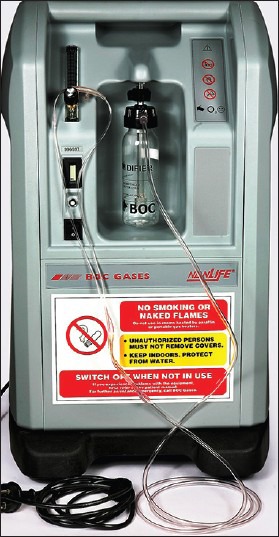
Oxygen concentrator
Liquid oxygen
Increasing hospital demands have led to the introduction of cryogenic liquid oxygen systems for both reserve and mains supply. The core component of the CLS is the vacuum insulated evaporator (VIE). The system also includes a control panel and a telemetry system. Hospitals should have a minimum of 2 weeks supply of oxygen, but this should be increased if there are some delivery related problems.
Large amount of liquid oxygen is stored in a VIE as bulk oxygen is more economical and convenient in comparison with cylinder manifolds. Liquid oxygen is derived by the fractional distillation of liquid air. One volume of liquid oxygen yields 842 times of its volume of oxygen in gaseous form at 15°C temperature and one atmospheric pressure.[6] VIE is a double walled large insulating flask where inner stainless steel shell is set apart from the outer carbon steel casing by a layer of perlite (insulating material) with a high performance vacuum of 0.16-0.3 kPa.[7] Liquid oxygen (upto 1500 L) is stocked inside the container at about −160°C, much lower than the critical temperature (−118°C) of oxygen and at a pressure of 5-10 atmospheres. Liquid oxygen sits at the bottom of the vessel whilst gas sits at the top at a pressure of 10.5 bar. The temperature of the vessel is maintained by the high-vacuum shell. Because it is impossible to maintain perfect insulation, the inner container is trying to draw heat from the atmosphere, although the effects of this are offset by the evaporation of the liquid during its use. The storage vessel rests on a weighing balance to measure the mass of the liquid. More recently, a differential pressure gauge, which measures the pressure difference between the bottom and top of the vessel, has been used instead. This alerts the distributor at times of low supply.[8] As liquid oxygen evaporates, its mass decreases, reducing the pressure at the bottom. If there is lesser demand, the pressure inside the vessel rises and to prevent this safety relief valve opens at 1700 kPa and blows the gas to the atmosphere. Conversely, the pressure in the vessel will tend to fall if there is a high demand. There is a vapour withdrawal line at the top of the VIE, from which liquid oxygen can be withdrawn; the liquid can be made to join the vapour line downstream of the restrictor and pass either through the superheater or back to the top of the VIE. After passing through the superheater (made of uninsulated coils of copper tubing), the oxygen vapour is passed through a series of pressure regulators to reduce the pressure down to the distribution pipeline pressure of 410 kPa. Fresh supplies of liquid oxygen are pumped from a tanker into the vessel when required [Figures 2a and b].
Figure 2.
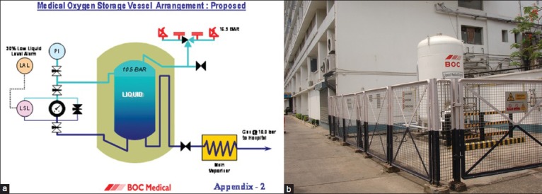
(a) Vacuum insulated evaporator (schematic), (b) Vacuum insulated evaporator (pictorial)
CONTROL PANEL
It controls the pressure and flow of gas to the pipeline. It is designed to pass a flow of 3000 L/min from the main VIE supply and 1500 L/min through the emergency cylinder manifold. It has duplicate regulators for safety. These are designed to control the pressure at 4.1 bar for the main supply and 3.7 bar for the emergency cylinder supply.
The control panel relays alarm conditions to a central alarm panel, usually located in the emergency department, with the secondary panels located in critical areas throughout the hospital.
Telemetry system
It provides a continuous monitoring.
Installation site requirements
It should be located inside a fenced compound, be accessible to the road tankers. All hazardous buildings, flammable materials, public access, vehicles and surface water drains must be at least 5 m and in some cases 8 m from the nearest point of the compound. The compound directly in front of the fill connection must be concrete and should be designed to contain any liquid spillage as risk of fire is increased in case of liquid spillage. Tar and asphalt should never be used in the vicinity as they form an explosive mixture when in contact with liquid oxygen.
GAS CYLINDERS
High pressure cylinders are used to store and transport compressed or liquid medical gases. Originally made from steel, gas cylinders are now constructed of a variety of materials to allow for their use in many different environmental conditions. Aluminium cylinders are available for use in magnetic resonance imaging scanners. Molybdenum steel is lightweight, resistant to corrosion and of high tensile strength. There are some cylinders made from aluminium or steel with a Kevlar or carbon fibre outer shell that allow lightweight cylinders that can be filled to a higher filling pressure.[9] Light weight cylinders with fitted handle are available for transportation of patients. Transportable gas cylinders are used to resuscitate a non-breathing patient while performing cardio-pulmonary resuscitation A demand valve releases higher flow of oxygen in response to increased demand. Contrary to continuous flow, demand valves conserve oxygen by restricting transmission to the inspiratory phase of respiration and minimising the misuse that takes place during expiration. Cylinders are colour coded and contain either liquid in association with a vapour or gas, depending on the critical temperature of the substance.
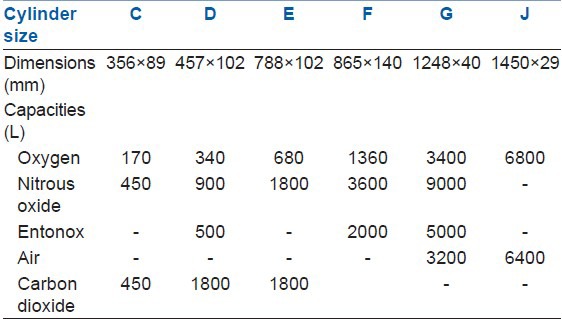
The top end of the cylinder is called the neck and this ends in a tapered screw thread into which the valve is fitted. The thread is sealed with a material that melts if the cylinder is exposed to intense heat. This allows the gas to escape so reducing the risk of explosion. The year when the cylinder was last examined and the date of the next test is indicated by a plastic disc around the neck of the cylinder [Tables 1 and 2].[6]
Table 1.
Physical properties and colour coding of medical gases in cylinders[10]

Table 2.
Medical gas cylinder nomenclature, dimensions and gas capacities[[10]
Valve block
The cylinder valve acts as a mechanism for entry and exit of the gas pathway. A compressible yoke sealing (Bodok seal) is placed between the valve outlet and apparatus to make a gas-tight joint. The valve block screws into the open end of the cylinder neck. The valve is made up of brass and sometimes chromium plated. Turning a longitudinal spindle (which is set within the gland and secured tightly into the valve block) opens the valve. A safety outlet is fitted between the block and the cylinder neck. It is made up of a material (Wood's metal) that melts at a low temperature, allowing the gas to escape in a fire, thus reducing the risk of explosion. The types of gas cylinder valves are: Bull-nose, Hand-wheel and Integral valves. There is a newly designed valve which allows keyless manual turning on and off.
Pin index safety system
This prevents errors of identification of cylinders. A particular pin configuration exists for each medical gas on the yoke of the anaesthesia machine. There are holes on the valve block which allows only the correct gas cylinder to be fitted properly into the yoke. The exit port of gas in the valve block will seal against the washer of the yoke when the pin and the holes are properly aligned. If multiple washers are used, the pins in the yoke may not extrude far enough to engage the mating holes and the PISS won’t work properly [Figure 3].
Figure 3.
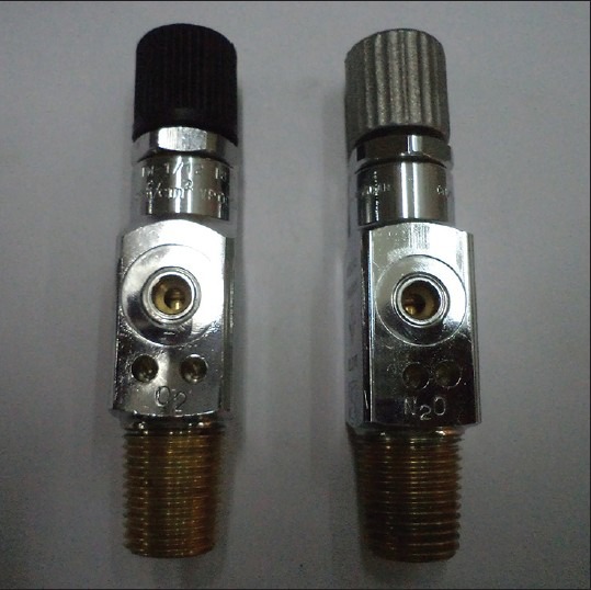
Pin index safety system
Larger cylinders have “Bull nose” connections, which allow a regulator to be screwed into place. These regulators do not have any gas-specific connections.
Size
Cylinders are manufactured in different sizes (A-J). Sizes A and H are not used for medical gases. Cylinders attached to the anaesthetic machine are usually of size E.
Labelling
The contents of the cylinder can be identified by the label of the cylinder. The cylinder label consists of the following details:
Name, chemical symbol, pharmaceutical form, specification of the product.
License number and the proportion of the constituent gases in a gas mixture.
Substance identification number and batch number.
Hazard warnings and safety instructions.
Cylinder code size.
Cylinder volume.
Maximum cylinder pressure.
Filling date, shelf life and expiry date.
Directions for use.
Storage and handling precautions.
The marks engraved on the cylinders are:
Test pressure.
Date of the last test performed.
Chemical formula of the cylinder's content.
Tare weight.
Testing
Cylinders in use are checked and tested by manufacturers at regular intervals, usually of 5 years. They undergo internal examination with an endoscope. Flattening, bend and impact tests are carried out on at least one cylinder in every hundred. They undergo hydraulic or pressure test: The cylinder is subjected to high pressures of about 22,000 kPa, which is more than 50% above their normal working pressure. Every hundredth cylinder after manufacture is cut into strips and tested for tensile strength.
Filling
For gases that are stored in cylinders as compressed gases (like air, oxygen and helium), the degree of filling is determined by measuring the pressure in the cylinder. As the cylinder empties, the pressure reduces linearly and indicates accurately how much gas is left in the cylinder.
Gases like nitrous oxide and carbon dioxide are liquefied under pressure in the cylinders. The pressure gauge reads the pressure of the vapour phase above the liquid and does not indicate about the amount of the liquid in the cylinder. As the gas is exhausted, the liquid boils to replace the used gas and the pressure remains constant at a constant temperature. The only method to determine the amount of filling is to subtract the cylinder's tare weight (weight of empty cylinder) from its actual weight.
Cylinders that contain liquefied gases are never completely filled with liquid, as rise in temperature would result in the rise in pressure and the risk of cylinder rupture. Therefore, these cylinders are only partially filled up with liquid, depending on the climate in which they are used. The filling ratio is the ratio of the mass of the gas in the cylinder to the mass of water that the cylinder can hold when full. As 1 L of water weighs 1 kg, the filling ratio of a cylinder is the mass of nitrous oxide in kilograms divided by the internal volume of the cylinder in litres.[11] In a temperate climate, the filling ratio for both nitrous oxide and carbon dioxide is 0.75. In tropical climates, the cylinders are filled to a filling ratio of 0.67.
Duration of gas flow
An E cylinders contain 22 cubic feet (cu ft) of oxygen when full (2200 psi pressure).
One cubic foot of oxygen equals 28.3 L.
Now, Tank Factor: (22 × 28.3) L/2200 psi = 0.28 L/psi.
-
Therefore, the time duration for which the tank would last (in minutes).
= (Tank factor [gauge pressure – 500])/L flow.
= (0.28L/psi [2000 psi – 500 psi])/8 L/min.
= 52.5 min.
Safety precautions
The plastic wrapping of the valve must be removed prior to use. The valve should be slightly opened and closed (cracked) with the port pointed away from the user before connecting the cylinder to the anaesthetic machine. This reduces the possibility of explosion and clears particles of dust, oil and grease from the exit port, which would otherwise enter the anaesthesia machine.
The valve should be opened slowly when attached to the anaesthesia machine or regulator. If gas passes quickly into the space between the valve and the yoke, the rapid recompression will generate a large amount of heat. This is an adiabatic process (heat is neither lost nor gained from environment). Particles of dust, grease present in this space may be ignited by heat, causing a flash fire or explosion. The valve should be opened slowly when attached to the anaesthesia machine or regulator.
The cylinder valve should be fully open when in use (number of revolutions required to open it fully depends on the type of valve).
During closure, over tightening of the valve should be avoided. This might lead to damage to the seal between the valve and the cylinder neck. The Bodok seal should be inspected for damage prior to use. A spare seal should be readily available.
CYLINDER HAZARDS
Incorrect tank (despite PISS), incorrect contents, incorrect valves, wrong colour, wrong label, damaged valves, suffocation, fire, explosions (rapid escape of contents or rocketing of tank), contamination, theft of N2O (substance abuse), overfilled, thermal injury (frostbite reported with recreational use of N2O).
Storage
They should not be stored with non-medical cylinders. The store area should:
Be kept under cover or inside a locked area and not be subjected to extremes of temperature.
Be such designed to prevent unauthorised entry.
Have vehicular access for delivery and a level floor surface.
Be well away from combustible materials or sources of ignition.
Have warning notices to prohibit smoking or naked flames.
Allow large cylinders to be stored vertically and small cylinders horizontally.
Be clean, dry and well-ventilated.
Allow for rotation of cylinders, so that the oldest are used first.
Allow segregation of full and empty cylinders and those of different gases.
Permit separation of different gases and cylinder sizes.
Cylinder manifold
Manifolds are used to supply oxygen, nitrous oxide and entonox. There are minor differences in operation for each gas, in general they are designed and operate along the same principles. An average cylinder manifold configuration contains two equal banks of gas cylinders with a centrally located control panel, which provides a normal output pressure of four bar. Large cylinders are usually divided into two groups: Primary (duty bank) and secondary (standby bank). The two groups alternate in supplying the pipelines. The number of the cylinders depends on the expected demand. All cylinders in each group are connected to the manifold via a copper tail-pipe with a gas specific connection and seal. Each connection has a non-return valve fitted to enable single cylinder to be changed if a leak or tail-pipe rupture occurs. The cylinders are held captive by individual chains to the backbar. All the cylinders are connected through non-return valves to a common pipe. This in turn is connected to the pipeline through pressure regulators. The total storage capacity of the manifold should be based on 1 weeks supply with a minimum of 2 days’ supply on each bank and a supply of 3 days spare cylinders held in the manifold room. Any additional cylinders should be held in the general medical gas store. Nitrous oxide manifolds have heaters fitted to the supply line to prevent freezing during periods of high demand.
In either group, all the cylinder valves are opened. This allows them to empty simultaneously. The supply is automatically changed to the secondary group when the primary group is nearly empty. The changeover is achieved through a pressure-sensitive device that detects when the cylinders are nearly empty. The changeover activates an electrical signalling system to alert the staff about the need to change the cylinders. There is a safety system[7] in place alongside mechanisms to prevent discharging the entire gas contents. A discharge pipe is connected to allow the venting of excess gas into the atmosphere.
There should be no disruption of the gas supply via the cylinder manifold in the event of the electricity failure. Either both banks or the default bank will continue to provide oxygen supply till power is restored [Figure 4].
Figure 4.
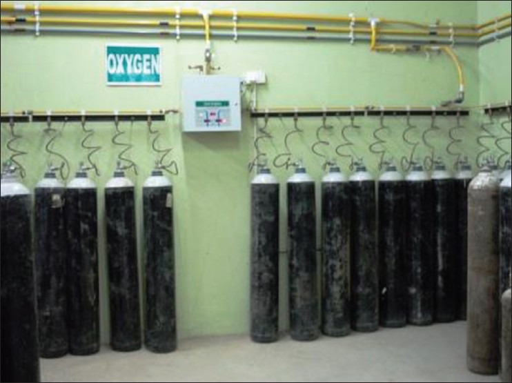
Cylinder manifold
Safety precautions
The manifold should be housed in a well-ventilated room built from fire-proof material, either brick or concrete, away from the main building of the hospital. The manifold room should not be used as a general cylinder store. It should ideally be located to enable the access of the delivery vehicles to prevent manhandling of the cylinders for long distances. The room should be well-lit, temperature-controlled at 10-40°C and should have sufficient warning signs on the outside and inside of the building. All empty cylinders should be removed immediately from the manifold room. Only trained persons should be permitted to change cylinders and an activity log should be completed when cylinders are changed.
PIPELINES
Piped medical gas and vacuum (PMGV) is a system where gases are delivered from central supply points to different supply points in the hospital at a pressure of about 400 kPa.
Oxygen, nitrous oxide, entonox and medical vacuum are commonly supplied throughout the pipeline system which is made of special high quality phosphorus-containing, de-oxidized, non-arsenical copper alloy, which prevents degradation of the gases it contains as well as has bacterio-static properties. The fittings used must be copper- to-copper only, made with a special silver solder brazing alloy. This reduces pipe corrosion. The size of the pipes differs according to demand that they carry. Pipes with a 42 mm diameter are usually used for leaving the manifold. The smaller 15 mm concealed pipelines ultimately end as gas outlets either flush fitting on walls or as overhead boom or as suspended hoses that are gang mounted. These terminal gas outlets [Figure 5] are colour-coded, labelled with gas name and have self-sealing sockets which shut down automatically to enable servicing work on individual units without shutting down large parts of the system. These should have a quick connect probe assembly that can be removed for servicing but cannot be accidentally connected to a different gas outlet.
Figure 5.
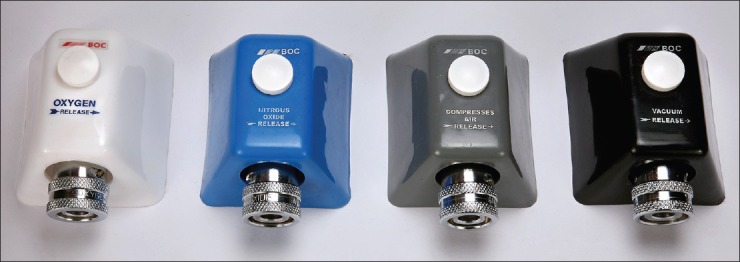
Terminal wall outlets
Flexible colour-coded hoses connect the outlets to the anaesthetic machine. They have a Schraeder probe at one end and a gas-specific threaded connector at the other end. The gas specific Schraeder valve, uses a unique collar indexing system with a unique diameter that fits the matching recess on the terminal outlet for a specific gas only [Figure 6]. At the anaesthetic machine end, each hose is connected with a unique connector. This takes the form of a nut and probe. The nut has the same diameter and thread for all the gas services but can be attached to the anaesthetic machine only when the probe is correctly engaged. The profile has two cylindrical shapes, which form a unique combination. In the UK, this is called a non-interchangeable screw threaded connection (NIST).[12] This term is ambiguous as the threaded connector is not gas-specific. In the USA, a similar system is employed called diameter indexed safety system (DISS). However, the diameters of the constituents of the various connections are smaller and are not compatible with the NIST system [Figure 7].
Figure 6.
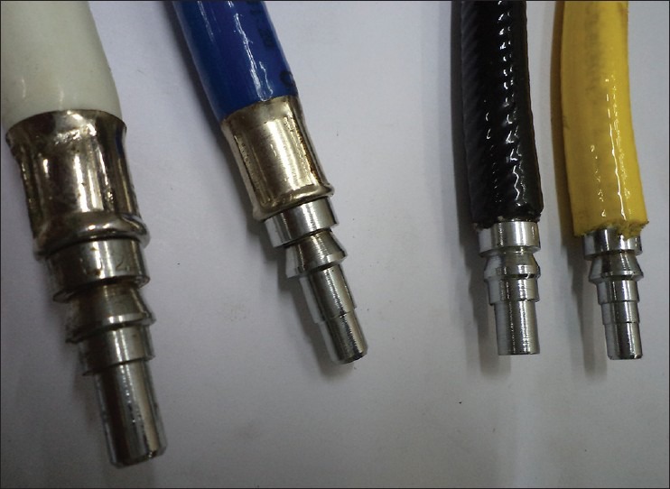
Schraeder probes for different gases
Figure 7.
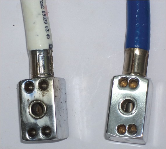
Non-interchangeable screw threaded connection for different gases
The hose assemblies are manufactured in dedicated units. The metal ferrules (stainless steel sleeves placed on the outside of the hosepipe) hold the hoses and are designed to withstand the forces at removal as well as compressing the hosepipe into the serrated spigots of the terminal outlets and the NIST probes with such force that if an attempt was made to pull the two apart, the hose would stretch and break before the components separated. This thereby prevents the wrong connector being reattached with the wrong hose.[12]
Isolation of pipeline network is present in many places by isolating valves commissioned at strategic points, most commonly seen in the entrance of each clinical sector. These are called area valve service unit (AVSU) [Figure 8]. The isolation valves of AVSU can be accessed by standard break glass or plastic push/pull-out technique to isolate the gas delivery to a particular clinical territory in case of maintenance, installation, fire or any other emergency. The AVSU also provides self-sealing.
Figure 8.
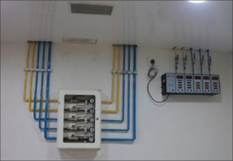
Area valve service unit
Pipeline problems
Some of the problems are inadequate pressure (most commonly reported), damage during construction projects, fire, theft of N2O tanks, environmental (earthquakes, lightning), depletion of central supply, human error (accidental closure of shutoff valve), obstruction (debris following installation), kinking, leak, obstruction of a hose, contamination.
Safety precautions
A reserve bank of cylinders should be available should the primary supply fail. Low pressure alarms detect gas supply failure. Single hose test is performed to detect cross-connection. Tug test is performed to detect misconnection. Regulations for PMGV installation, repair and modification are enforced. Anaesthesiologists are responsible for the gases supplied from the terminal outlet to the anaesthetic machine. Pharmacy, supplies and engineering departments share the responsibility for the gas pipelines “behind the wall.” There is the risk of fire from worn or damaged hoses that are designed to carry gases under pressure from a primary source such as ventilators and anaesthetic machines. Due to heavy wear and tear, the risk of rupture is greatest in oxygen hoses used with transport devices. Regular inspection and replacement at an interval of every 2-5 years, of all medical gas hoses is recommended.
NITROUS OXIDE
N2O is produced by heating ammonium nitrate at 250°C. If the temperature is controlled properly, there would be lesser production of ammonia and higher oxides of nitrogen. These impurities are removed by washing with water, acid, alkali and permanganate solutions before drying and insertion as liquid into cylinders. The nitrous oxide is supplied in cylinders containing between 450 and 18,000 L of gas.
Nitrous oxide has a critical temperature above the room temperature, so it is stored as a liquid in pressurised cylinders, with nitrous oxide vapour present in the space above the liquid. The actual pressure of the full cylinder lies between 4400 and 5000 kPa. For vapourisation of the liquid, energy is provided from the local environment - the latent heat of vapourisation. This results in the significant fall in temperature within the cylinders pressure regulator, thus freezing any water vapour present and causing possible obstruction of the regulator outlet. This can be prevented by thermostatically-controlled regulators.
ENTONOX
It is a 50:50 mixture of oxygen and nitrous oxide supplied as a gas. Gas mixture is stored in cylinders or cylinder banks and delivered using a two stage pressure regulator, the second one incorporating a demand valve. Gas flow occurs with the inspiratory effort of the patient. It is manufactured by mixing these two separate components together utilising the Poynting effect or lamination effect.
Poynting effect
When gaseous oxygen at high pressure is passed through liquid nitrous oxide, vaporisation of liquid occurs, forming a 50:50 mixture of oxygen and nitrous oxide.[10]
Pseudocritical temperature
It is the temperature at which the mixture of gases will separate out into its constituent parts.[13]
Entonox separates out into nitrous oxide and oxygen at −5.5°C at 117 bars, −7°C at 137 bar (cylinder pressure) and −30°C at 4 bar (pipeline pressure). If the pseudocritical temperature is reached, there is a danger of an initial 100% oxygen delivery followed by 100% nitrous oxide – a hypoxic gas. To avoid this, cylinders must be stored horizontally for 24 h well above its critical temperature prior to use. If the contents are well-mixed by repeated inversion, cylinders can be used earlier than 24 h. Large cylinders equipped with a dip tube with its tip ending in the liquid phase may also be used. This results in the liquid phase being used first, preventing the delivery of an oxygen concentration of less than 20%.
MEDICAL AIR
Medical air is mainly used in respiratory therapy as a power source for ventilators and for blending with oxygen. It is also used as the driving gas for nebulised drugs and chemotherapy agents. Surgical air is also used, at a higher pressure, to power a variety of surgical tools and other devices such as tourniquets pneumatic drills and saws (as an alternative, nitrogen can be used for this purpose). It is subject to European Pharmacopoeia[8] standards even though it is derived directly from our surroundings in many cases. Medical air is provided by three methods: Compressed air, synthetic air and cylinder manifolds.[2]
Compressed medical air is formed by drawing ambient air into the compressor. The system is so designed that if one compressor is non-functional, then the remaining pumps can maintain the service demand. The compressors provide this compressed air to a receiver and then to a series of filter driers and separators, which removes the condensed water, particulate matter and lubricating oil from the system before the compressed air enters the pipeline supply system otherwise oil and raised partial pressure of oxygen could be explosive. Regulators then reduce the pressure to 400 kPa. The surgical air required for equipment operation is supplied at 700 kpa through separate pipelines. Non-particulate impurities such as carbon monoxide and sulphur dioxide are not removed by the filtration system and in areas of high air pollution, may result in the supply of air of inadequate purity.
Although it is not sterile, medical grade air is clean and at standard temperature and pressure should not contain more than:
A total of 0.5 mg of particulate oil mist/cubic metre of air, 5.5 mg of carbon monoxide/cubic metre of air, 900 mg carbon dioxide/cubic metre of air, no moisture, no bacterial contamination.
Synthetic air is prepared by blending liquid nitrogen with liquid oxygen in the gaseous state. Its advantage is that no power supply is required and there are no contamination problems. Where such systems are installed to provide both oxygen and medical air, nitrogen can be used for the power source for surgical tools.
HELIOX
Over the last decade, a mixture of 21% oxygen and helium has become a focus of interest particularly in the treatment of acute exacerbation of bronchial asthma.[13] The low density (0.1669) of helium allows mixtures that can be more easily breathed than natural air and hence reduces the work of breathing. Apart from being a noble gas, helium is the second most abundant element in the universe. It is produced by the fractional distillation of natural gas, where concentration is as high as 1%.[1] The gas mixture, heliox is stored in cylinders with a black body and white/brown quarter shoulders at a pressure of 13,700 kPa in its gaseous state.[6]
CARBON DIOXIDE
It is readily available as a by-product of the manufacturing process of hydrogen[14] (for ammonia and other hydrogenation processes). Reaction of petroleum or natural gas with steam and/or oxygen gives a mixture of hydrogen and carbon monoxide, which can then be reacted with more steam to give hydrogen and carbon dioxide. The latter is then separated from hydrogen by absorption into an alkaline medium from which nearly pure CO2 is regenerated. The by-product gas is then purified and dried prior to liquefaction and filling of the cylinders. It is most commonly used as the insufflation gas during laparoscopy. It was however used as a respiratory stimulant in the 1930s during respiratory arrests and was initially incorporated into the anaesthesia machines. Deaths related to its misuse led to initially the production of the flow meters capable of delivering only 600 ml/min, then to the blanking of cylinder yokes and finally to the abandonment of its use.
MEDICAL VACUUM
It is considered as a part of the gas-supply infrastructure although it is not technically a gas. The system consists of a pump, receiver and a filter. The pump is capable of creating a negative pressure of −400 mm Hg and can accommodate an airflow of 40 L/min. Gas is sucked into the system via one or two traps to reduce its contamination and then into a reservoir with a pressure of −550 to −650 mm Hg. The vacuum is maintained by pumps that in common with the medical air system are able to provide a fully functional system if one is out of service.[7]
SUMMARY
Patient safety is of principal concern in the architecture, installation, commissioning and service of anaesthesia gas supply system. Many inbuilt safety areas are incorporated within the system. Oxygen is one of the hugely utilised medical gases, intended primarily for life support, anaesthesia and respiratory therapy. Primary utility of medical air is as driving source of ventilators and nebulisers. Medical air is commonly combined with air or oxygen for mechanical ventilation of patients in the operation room or critical care unit. Nitrous oxide is frequently mixed with air or oxygen to serve the purpose of analgesia and anaesthesia. A 50% mixture of oxygen and nitrous oxide, popularly known as entonox is used as a labour analgesia in maternity suites. Carbon dioxide is required regularly for insufflations during laparoscopic surgeries. Helium-oxygen mixture is of benefit to treat patients with airway obstruction and also to alleviate respiratory distress. Medical vacuum is catered almost in every clinical area powered by centrally placed vacuum pumps. Handling, transportation and storage of anaesthetic gas should be dealt with extreme caution. Risk assessment should include concerns related to use of oxygen and other gases.
ACKNOWLEDGMENTS
Authors sincerely acknowledge the help of Linde India Ltd. and Praxair India Pvt. Ltd. for providing the photographs and giving permission to publish the same in the Indian Journal of Anaesthesia.
Footnotes
Source of Support: Nil
Conflict of Interest: None declared
REFERENCES
- 1.Westwood M, Riley W. Medical gases, their storage and delivery. Anaesth Intensive Care Med. 2012;13:533–8. [Google Scholar]
- 2.Love-Jones S, Magee P. Medical gases, their storage and delivery. Anaesth Intensive Care Med. 2007;8:2–6. [Google Scholar]
- 3.Spence AA, Fee JP, Nunn G, Ross J, Garrett M, Henrys P, et al., editors. 2nd ed. Oxford: 2005. Medical Gases: Their Properties and Uses; pp. 85–96. [Google Scholar]
- 4.Molecular products. Technical data sheet oxygen generator EO2-26. [Last accessed on 2013 Jun 25]. Available from: http://www.molecularproducts.com/products/eo2.26p100n11/eo2-26/details .
- 5. [Last accessed on 2013 Jun 25]. Available from: http://www.bbb.co.uk/schools/gcsebitesize/science/edexcel_pre_2011/oneearth/usefulproductsrev2.shtml .
- 6.Al-Shaikh B, Stacy S. 4th ed. London: Churchill Livingstone, Elsevier; 2013. Essentials of Anaesthetic Equipment; pp. 2–12. [Google Scholar]
- 7.London: The Stationery Office; 2006. Department of Health. Health technical memorandum 02-01. Medical Gas Pipeline Systems, Part A Design, Installation, Validation and Verification; pp. 41–51. [Google Scholar]
- 8.Highley D. Medical gases, their storage and delivery. Anaesth Intensive Care Med. 2009;10:523–7. [Google Scholar]
- 9.British Oxygen Company Group PLC. Cylinder data chart. [Last accessed on 2013 Jun 25]. Available from: http://www.bocmedical.co.uk .
- 10.Magee P, Tooley M. Gas supply and the anaesthetic machine. In: Magee P, Tooley M, editors. The Physics, Clinical Measurement and Equipment of Anaesthetic Practice for the FRCA. 2nd ed. New York: Oxford University Press; 2011. pp. 287–300. [Google Scholar]
- 11.Lovell T. Medical gases, their storage and delivery. Anaesth Intensive Care Med. 2004;5:10–4. [Google Scholar]
- 12.Bland H. The supply of anaesthetic and other medical gases. In: Davey A, Diba A, editors. Ward's Anaesthetic Equipment. 5th ed. China: Elsevier Saunders; 2005. pp. 23–45. [Google Scholar]
- 13.Liu W, Khatibi N, Sridharan A, Zhang JH. Application of medical gases in the field of neurobiology. Med Gas Res. 2011;1:13. doi: 10.1186/2045-9912-1-13. [DOI] [PMC free article] [PubMed] [Google Scholar]
- 14.Spence AA, Fee JP, Nunn G, Ross J, Garrett M, Henrys P, et al., editors. 2nd ed. Oxford: 2005. Medical Gases: Their Properties and Uses; pp. 135–6. [Google Scholar]


