Abstract
Invention of oxygen cylinder was one of the most important developments in the field of medical practice. Oxygen and other gases were compressed and stored at high pressure in seamless containers constructed from hand-forged steel in1880. Materials technology has continued to evolve and now medical gas cylinders are generally made of steel alloys or aluminum. The filling pressure as well as capacity has increased considerably while at the same time the weight of cylinders has reduced. Today oxygen cylinder of equivalent size holds a third more oxygen but weighs about 20 kg less. The cylinders are of varying sizes and are color coded. They are tested at regular intervals by the manufacturer using hydraulic, impact, and tensile tests. The top end of the cylinder is fitted with a valve with a variety of number and markings stamped on it. Common valve types include: Pin index valve, bull nose, hand wheel and integral valve. The type of valve varies with cylinder size. Small cylinders have a pin index valve while large have a bull nose type. Safety features in the cylinder are: Color coding, pin index, pressure relief device, Bodok seal, and label attached etc., Safety rules and guidelines must be followed during storage, installation and use of cylinders to ensure safety of patients, hospital personnel and the environment.
Keywords: Cylinders, installation of cylinders, medical and anaesthetic gases, pin index safety system, safety devices, testing, valves
INTRODUCTION
Gas cylinder is a term that is commonly used to describe a pressurized container used for storage and transport. The gases used in anaesthesia are generally supplied under high pressure, either in cylinders or via pipeline with cylinders on anaesthesia machines for emergency backup. Oxygen, nitrous oxide, and medical air are usually supplied from pipeline. Entonox in some hospitals is also supplied via pipeline though it is more common to be supplied by portable cylinders. Bulk supply of oxygen in the hospitals is by cryogenic liquid system, liquid cylinder installation or from the oxygen concentrator.[1,2] Air is supplied either as pressurized cylinders or from compressors. Bulk production of oxygen is usually by fractional distillation of liquid air. In every country there are a series of regulations and standards for manufacture and the use of medical cylinders. While regulatory measures are designed to ensure safety in the manufacture and distribution of medical gases, sporadic accidents do occur[3] which have the potential to cause injury to patients, doctors or paramedic staff. Therefore, safety should be the highest priority.
CONSTRUCTION OF CYLINDERS
Medical gas cylinders were traditionally constructed of low carbon steel. Now they are constructed of light weight chrome molybdenum steel, aluminum or a composite (such as aluminum wrapped in carbon fiber). Special cylinders made from aluminum are useful in magnetic resonance imaging (MRI) room. Typical wall thickness of steel cylinders is 3 mm and that of an aluminum alloy cylinder is 6 mm2. Composite cylinders are manufactured from either light weight steel or aluminum liners[1] and are encased within a high density polyethylene jacket or wrapped by carbon fiber, Kevlar, Twaron or glass fiber. These cylinders are ultra-light in weight, extremely durable and can be filled with high pressure of upto 4000 kPa.[1] They can hold 30% more gas than an aluminum cylinder of comparable size and 70% lighter in weight than steel cylinder. Composite cylinders are used by firefighters, paramedics, and emergency first responders.
COMPONENTS OF CYLINDER
Body
The cylinder has a body, shoulder, and a neck. The curved upper part of the body is called as shoulder which tapers in a neck. The neck ends in a tapered screw thread into which the valve is fitted. When the valve is screwed to cylinder neck, a fusible material (Wood's Metal) is used to seal leaks between the valve and the cylinder which melts if the cylinder is exposed to intense heat. This allows gas to release and lessens the risk of explosion.[1]
Valve
The valve is made of bronze or brass and is most fragile part of cylinder, therefore provided with a metal protection cap to protect [Figure 1]. It allows the cylinder to be turned on and off and provides a means by which the cylinders are filled and connected to yoke assembly on anaesthesia machine or to regulator. The gas exits through the port. The valve contains a stem or shaft, which is rotated for opening or closing of cylinder. When the valve is opened the stem moves upward and gas flows to the port. During closure, the stem seals against the seat [Figure 2]. Two types of valves are in use. In the packed valve, the stem is sealed by resilient packing such as Teflon. In Diaphragm valve, a diaphragm separates upper and lower stem. Lower stem shuts or allows gas flow through the valve. The latter can be opened by only ½ or ¾ turns and is less likely to leak.[4]
Figure 1.
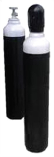
Medical-oxygen-cylinder with protective cap
Figure 2.
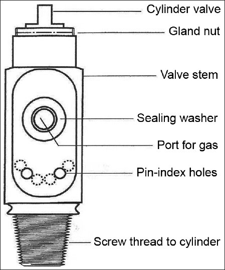
Cylinder valve
Pressure relief device is fitted on cylinders with the aim to vent the cylinder contents to atmosphere if the pressure in the cylinder increases to a dangerous level as a result of high temperature or overfilling.[5] They are of three types: Burst disk, fusible plug, and combination of two. Burst disk is most commonly used. It is a small metal gasket which bursts at a pre-determined pressure.
Pressure relief valve is a spring-loaded device designed to re-close and prevent gas in cylinder from being discharged after a set pressure has been restored.[2]
Conical depression
On small cylinder valves a conical depression is present that receives the retaining screw of the yoke.
Non-interchangeable safety system was introduced to prevent coupling of anaesthetic gas cylinders to wrong manifold or inlet of anaesthesia machine by Dr Philip Woodbridge.
Pin index safety system
It has a unique configuration of holes and pins which match precisely to eliminate connection of the wrong cylinder to equipment, thus prevents delivery of wrong gas to patients.[1,2,6] This system is also used by supplier to fill correct gas in the cylinder.[7] It incorporates two holes in specific positions on the cylinder valve below the outlet port [Figure 3]. The cylinder can only be connected to a yoke or pressure regulator with a matching pair of pins. The holes in the cylinder valve accept pins 4 mm diameter by 6 mm long.[2] Unless pins and holes are aligned, the port will not seal and gas will not pass to the anesthesia machine. Each gas or combination of gases has a specific pin arrangement [Table 1]. Pin index valves are fitted in small cylinders which are commonly connected directly to the anesthesia machine. Side spindle pin index valves are fitted in large cylinders of medical O2, air and Entonox for pipeline manifold and to F size Entonox cylinders.[1] Pin index cylinders require a seal between cylinder valve outlet and yoke. The seal is called as Bodok washer. It is a gasket with metal rim manufactured from a non-combustible material [Figure 4].
Figure 3.
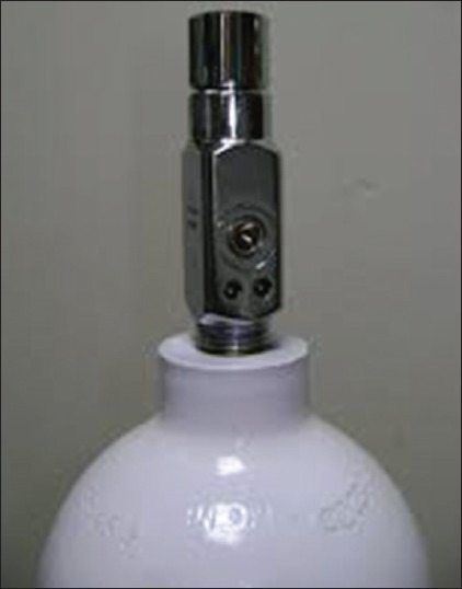
Pin index of oxygen cylinder
Table 1.
Color coding, pin index and physical state in cylinder of medical gases

Figure 4.
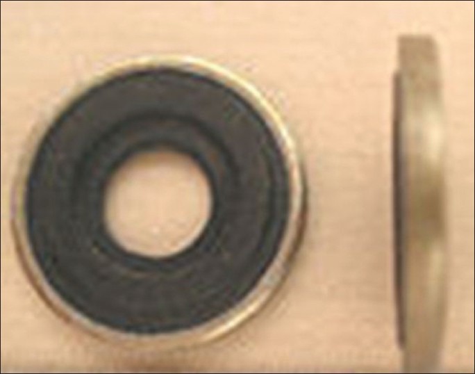
Bodok seal
Valve outlet connection for large cylinders
The valves of large cylinders (F and G size) of medical gases have threaded outlet often called as bull nose valve [Figure 5]. The valve is spindle type and has a 5/8 inch female outlet where a regulator is fitted. The nut causes the nipple to seal against the valve outlet and allows gas to pass.[1] A non-interchangeable screw thread system with a different number of threads per inch for each medical gas prevents wrong connection.[5] MPR (minimum pressure retention) device is fitted in all bull nose valves to ensure that a positive pressure of approximately 2 bars is retained in the cylinder to prevent ingress of moisture.[1]
Figure 5.
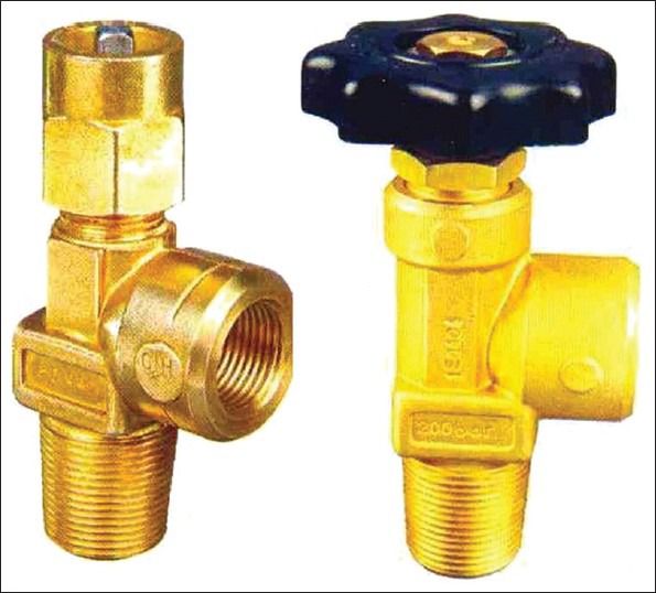
Bullnose and handwheel valve
Hand Wheel valve [Figure 5] is used for N2O (for use on manifold) and CO2 cylinders (size F and G). The valve may be surrounded by a protective guard. The valve has a gas specific side outlet and male thread. Bull nose and pin index cylinders require a wrench to open the valve while hand wheel cylinders do not require any additional equipment.[5,8]
Integral valve
The easily portable cylinders with inbuilt integral pressure regulators, flow meters, as well as handles is available for use[2] [Figure 6]. Regulator maintenance of hospital is not required for these valves.[9]
Figure 6.
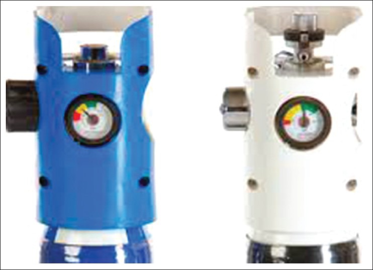
Integral valve
Cylinder size
Size of cylinder is defined by their capacity to hold water and range between 1.2 and 6550 L. The cylinders are produced in various sizes designated by a capital letter code with A being the smallest. Tables 2 and 3 give details of commonly used oxygen and nitrous cylinders.[1,2,5] On anaesthesia machine, work stations and for patient transportation and resuscitation, size E cylinder is most commonly used. On anaesthesia machine cylinders of 4.5 inch in diameter and 26 inches in length, 5.4 kg tare weight and smaller can be directly attached.
Table 2.
Size and specification of commonly used oxygen cylinders
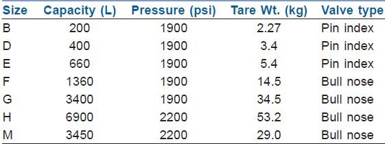
Table 3.
Relative size and specification of nitrous oxide cylinders

PRESSURE AND FILLING
The majority of the gases are stored in cylinders as compressed gases (oxygen, air, nitrogen, helium, heliox). These gases do not liquefy at ordinary ambient temperature regardless of pressure applied.[4] as their critical temperature is low. These cylinders are filled up to service pressure (defined as the maximum pressure to which the cylinder may be filled at 70° F) but they should be able to withstand 1.66 times the service pressure. The service pressure is usually 2000-2015 psi.[10] The quantity of gas in these cylinders can be estimated by using a pressure gauge, as the quantity is directly proportional to gauge pressure.[1,2,5] The amount of time that an anaesthesia machine can operate from E type cylinders is important. During use, an equation can help to estimate the remaining time proposed by Arlas.[11] Approximate remaining in hours = O2 cylinder pressure in psi/200 × O2 flow rate per minute. But this gives only a rough estimate.[12]
Nitrous oxide and carbon-dioxide liquefy at pressures to which cylinders are filled (at ambient temperature) and are therefore stored as liquids. These cylinders are not filled completely, but only up to a filling ratio (weight of gas in a cylinder/weight of water that cylinder can hold at 60°F).[3] The filling ratio of oxygen and nitrous oxide is 0.75, but 0.67 in the tropics. The contents of these cylinders can be accurately measured by weighing the cylinders (1.87 g/L of gas) rather than by pressure gauge.[13] The pressure depends on the vapor pressure of liquid and so does not indicate the amount of gas remaining in the cylinder as long as the contents are partly in the liquid phase. The pressure will remain same till all the liquid is converted to gas, after which the pressure falls until the cylinder is exhausted. Cylinder pressure varies only if temperature changes due to rapid emptying of cylinder causing cooling of contents due to absorption of latent heat of vaporization. Under this condition, cylinder pressure will decrease with cooling but will be restored as the cylinder warms up again.[7]
COLOR OF CYLINDERS
An international color code to aid in identification of gas cylinders was adopted by medical gas industry in 1949. Unfortunately, this has not been adopted by many countries, US uses green and Germany uses blue color for oxygen cylinders. International color code of various cylinders and that used in India are given in Table 1. Due to variation in color tones, chemical changes in paint pigments, color should not be used as a primary means for identification of cylinders.[2,7]
Cylinder identification
Each cylinder should have a label [Figure 7] which has all the informations about the cylinder for the users. The label has the following information:
Figure 7.
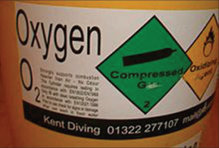
Oxygen cylinder label
Name and chemical symbol of gas.
Product specification.
Hazard warning diamond shaped figure denoting hazard class contained gas.
Name and address of cylinder manufacturer.
Cylinder contents in liters.
Tare weight (weight when empty).
Maximum cylinder pressure.
Cylinder size code.
Directions for use.
The cylinders have a tag attached which has three sections labeled, FULL, IN USE and EMPTY.
Periodic testing
Before releasing for distribution, a random cylinder from each batch is examined and tested by the manufacturer to verify that appropriate design and standard was followed. Each cylinder is visually checked before filling. The cylinder should be inspected endoscopically for cracks and defects on their inner side[14] and can also be tested ultrasonically.[7] The cylinders undergo various tests to ensure safety. The test is carried out every 10 years for steel cylinders and every 5 years for composite cylinders. A specific shape and color coded plastic ring around the cylinder neck indicates the time of next testing.
Hydraulic test
Is a measure of cylinder's elasticity.[8] The cylinder is connected by a thread to testing unit, filled with water and the water level is measured by gauge. The gauge is isolated and cylinder pressurized to 240 atmospheres. The pressure is released and gauge opened. The cylinder should stretch less than 0.02%.
Tensile test
Done in one out of 100 cylinders. The yield point should not be less than 15 tons per square inch.
Flattening test
The cylinder is kept between two compression blocks and pressure is applied from both sides until the distance between blocks remains 6 times the thickness of the wall of cylinder. The walls should not crack.
Impact test
Three of each, longitudinal and transverse stripes are taken from a finished cylinder and struck by mechanical hammer. Mean energy to produce the crack should not be less than 5 and 10 lb/ft for transverse and longitudinal strips, respectively.
Bend test
A ring of 25 mm width is cut from the cylinder and divided into strips. Each strip is bent inward until inner edges are a part, not greater than the diameter of strip.
Entonox
This is 50.50 mixtures of nitrous oxide and oxygen [Figure 8]. The premixed contents remain in gaseous phase at pressures and temperature at which N2O by itself would normally be a liquid (poynting effect).[1,15] Entonox is compressed in cylinders at a pressure of 13,700 kPa. Cylinders are colored blue with white quadrants on the shoulder. For filling, the cylinders are first filled with the correct weight of nitrous oxide. The cylinder is then inverted and oxygen is bubbled through. As oxygen dissolves in nitrous oxide, the latter vaporizes until all the liquid is vaporized. The mixture remains in gaseous state unless the temperature falls to −7°.[7]
Figure 8.
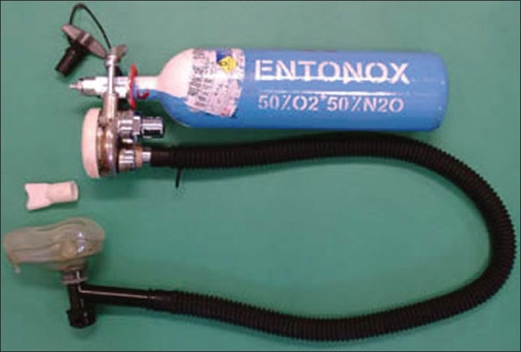
Entonox with delivery system
The gas mixture is delivered to patients using a two stage pressure regulator consisting of the BOC Entonox valve, the second incorporating a demand valve. This valve is now replaced by pneupac entonox valve. This also consists of a first stage pressure regulator connected by a narrow bore delivery tube to demand valve which has a 22 mm male connector that is attached to the mouthpiece or face mask. The tubing can be very long so Entonox cylinder can be stored remotely from demand valve in a warm area.[1] The delivery apparatus can deliver a peak inspiratory flow rate in excess of 275 L/minute. As the patient inspires through the mask or mouthpiece, the gas flows and ceases at the end of inspiration. Demand valve ensures that gas does not flow unless negative pressure is achieved. Airtight seal between mask and face are essential.
If Entonox cylinder is stored at cold temperature (−7°C), some N2O separates as liquid and may lead to delivery of uneven mixtures, too much O2 at the beginning and too much N2O later as the cylinder empties. Danger of separation can be avoided by storing the cylinders above 0°C, immersing the cylinder in water at 52°C, inverting it thrice or keeping it above a temperature of 10°C for 2 hours before use.[7,15]
Heliox
Heliox is a mixture of oxygen and helium. The latter is 86% less dense (0.179 g/L) than air (1.293 g/L).[5] A mixture of 21% oxygen and 79% of helium named as Heliox 21 is used to improve gaseous exchange in acute exacerbation of asthma and COPD [Figure 9].
Figure 9.
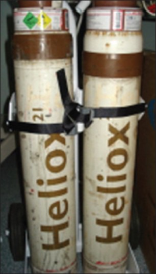
Heliox
Storage of cylinders
The storage area should be cool, dry, ventilated, clean area constructed of fire resistant material[16]
Have good access for deliveries and a reasonable level floor surface
Should have segregation of “Full” and “Empty cylinders”
Cylinders with an oldest fill date should be used first
Cylinders should not be stored in direct sunlight[10]
Easily visible sign such as no smoking, no open flames or sparks, no oil or grease etc., should be displayed
Cylinders should not be exposed to dampness, corrosive chemicals, fumes as they may damage cylinders and/or cause valve protection caps stick
The temperature should not go below 10°C where Entonox cylinders are stored
Cylinders should always be kept in place with chain or any other restraining device
The suitable trolley/cart should be used to transport and support the cylinders.
Handling and installation
Before using, the contents of the cylinder must be identified by reading the label[7] and also seeing the color of the cylinder
Full cylinders are fitted with tamper evident seal, usually a shrink wrapped around the valve, should be removed immediately before use[2]
Before connecting to yoke, the cylinder valve be cracked (i.e., Opened only slightly) to blow away any dust or flammable silting on the valve.
The person opening the cylinder should be positioned so that the valve outlet and/or the face of pressure gauge points away from self, patient and machine
Care should be taken to see that sealing washer (Bodok Seal) is present on the yoke and is in good condition to prevent leakage.[6,7] More than one washer should never be used as it can default PISS
The valve should be opened slowly to release the pressure gradually. Sudden opening can produce a shock wave in the pressure gauge and regulator and can damage parts. Also, if gas passes quickly in the space between the valve and yoke or regulator, it can generate a large amount of heat. As there is almost no time to dissipate, this constitutes an adiabatic process[1] (no heat is lost or gained from surrounding). The heat generated can ignite grease or any dust particle present, causing flash fire or explosion
The cylinders should never stand upright without support
Handling should only be by trained staff.
Problems and hazards of medical gases and cylinders
Wrong cylinder despite pin index safety system has been attached to yoke or regulator due to altered or broken pins or the use of more than one washer[17,18,19,20,21]
Problems of filling of wrong gas[17,23] and over or under filling of cylinder.
Wrong color coding – cylinder painted with other than standard color[24]
Wrong or ambiguous label[25]
Faulty delivery of oxygen[26]
Damaged valve[27]
Chemical contamination or moisture in gas[28]
Hazard due to fire and explosion
Physical injury to hospital personnel or patient if unrestricted cylinder falls.
SUMMARY
Medical gas cylinders are usually made of molybdenum steel or aluminum and contain pressurized or liquefied gases. They are of various sizes, color coded, undergo testing at periodic interval and have several safety features. Nitrous oxide and carbon-dioxide are stored as liquefied gases employing filling ratio whereas other gases stored as pressurized gases at 13700 kPa. Each cylinder has a label attached to identify contents of the cylinder. The main hazard arises from a large amount of stored energy the cylinders contain due to high pressure of gases, wrong contents, improper maintenance or human error. The hazards have the potential to harm the patients and health care providers. Therefore, proper precaution should be taken and backup plans must be instituted to minimize impact of any hazard.[5]
Footnotes
Source of Support: Nil
Conflict of Interest: None declared
REFERENCES
- 1.Bland H. The Supply of anesthetic and other medical gases. In: Davey AJ, Diba A, editors. Ward's Anesthetic Equipment. 5th ed. London: Elsevier Saunders; 2005. pp. 23–49. [Google Scholar]
- 2.Dorsch JA, Dorsch SE, editors. 5th ed. Philadelphia US: Lippincott Williams and Wilkins; 2008. Understanding Anesthesia Equipment. [Google Scholar]
- 3.Schumacher SD, Brockwell RC, Andrews JJ, Ogles D. Bulk liquid oxygen supply failure. Anesthesiology. 2004;100:186–9. doi: 10.1097/00000542-200401000-00032. [DOI] [PubMed] [Google Scholar]
- 4.Handbook of compressed gases. 3rd ed. Boston: Kluver Academic Publisher; 1999. Compressed Gas Association. [Google Scholar]
- 5.Sandberg W, Urman R, Ehrenfeld J. 1st ed. London: Elsevier Saunders; 2010. The MGH Textbook of Anesthetic Equipment. [Google Scholar]
- 6.Sinclair CM, Thadsad MK, Barker I. Modern anaesthetic machines. Contin Educ Anaesth Crit Care Pain. 2006;6:75–8. [Google Scholar]
- 7.Lin ES. Anaesthetic equipment. In: Pinhock CA, Lin T, Smith T, editors. Fundamentals of Anaesthesia. 1st ed. Cambridge England: Cambridge University Press; 2003. pp. 878–9. [Google Scholar]
- 8.Davey A, Ince CS, editors. 1st ed. Cambridge, England: Cambridge University Press; 1999. Fundamentals of Operating Department Practice. [Google Scholar]
- 9.Giruad C. Oxygen cylinder with an integrated pressure regulator and cylinder valve. Ann Fr Anesth Reanim. 2003;22:301–11. doi: 10.1016/s0750-7658(03)00039-x. [DOI] [PubMed] [Google Scholar]
- 10.Wyka KA, Mathews PJ, Rutkowski JA, editors. 2nd ed. Stamford, Connecticut, U.S: Cengage Learning; 2011. Foundations of Respiratory Care. [Google Scholar]
- 11.Arlas G. A method to quickly estimate remaining time for an oxygen E-cylinder. Anesth Analg. 2004;98:1190. doi: 10.1213/01.ANE.0000107601.21502.0F. [DOI] [PubMed] [Google Scholar]
- 12.Brockwill SC, Andrews JJ. Inhaled anesthetic delivery system. In: Miller RD, editor. Millers Anesthesia. 7th ed. Philadelphia: Churchill Livingstone; 2010. pp. 667–718. [Google Scholar]
- 13.Rousseau GF, Carr AS. Reserve nitrous oxide cylinder on anaesthetic machines: A survey of attitudes and equipment at a large DGH. Anaesthesia. 2000;55:883–5. doi: 10.1046/j.1365-2044.2000.01542.x. [DOI] [PubMed] [Google Scholar]
- 14.Vallis CJ, Hutton P, Clutton-Brock TH, Stedman R. The Anesthetic Machine and Breathing systems. In: Healy TE, Knight PR, editors. Wylie and Churchill-Davidsons's A Practice of Anesthesia. 7th ed. Arnold London: 2003. pp. 465–86. [Google Scholar]
- 15.Davies NJ, Cashman JN, editors. 13th ed. United Kingdom: Butterworth-Heinemann; 2006. Lee's Synopsis of Anaesthesia. [Google Scholar]
- 16.Guidance for the storage of gas cylinders in the workplace; GN2 (Revision 4) British Compressed Gas Association. 2011 [Google Scholar]
- 17.Petty WC. Medical gases: Hospital pipelines and medical gas cylinders: How safe are they? AANA J. 1995;63:307–12. [PubMed] [Google Scholar]
- 18.Mead P. Hazard with cylinder yoke. Anaesth Intensive Care. 1981;9:79–80. [Google Scholar]
- 19.Thomas AN, Hurst W, Saha B. Interchangeable oxygen and air connectors. Anaesthesia. 2001;56:1295–6. doi: 10.1046/j.1365-2044.2001.02369-7.x. [DOI] [PubMed] [Google Scholar]
- 20.Saha B, Thomas AN, Tuichi A. Interchangeable oxygen and carbon dioxide cylinders. Anaesthesia. 2005;60:827–8. doi: 10.1111/j.1365-2044.2005.04318.x. [DOI] [PubMed] [Google Scholar]
- 21.Chamley D, Trethowen L. Pin index failure. Anaesth Intensive Care. 1993;21:128–9. [PubMed] [Google Scholar]
- 22.Serlin S. Check for tanks (letter) Anesth Analg. 2004;98:870. doi: 10.1213/01.ane.0000106969.51344.35. [DOI] [PubMed] [Google Scholar]
- 23.Menon MR, Lett Z. Incorrectly filled cylinders. Anaesthesia. 1990;46:155–6. doi: 10.1111/j.1365-2044.1991.tb09379.x. [DOI] [PubMed] [Google Scholar]
- 24.Taylor NJ, Davison M. Inaccurate colour coding of medical gas cylinders. Anaesthesia. 2009;64:690. doi: 10.1111/j.1365-2044.2009.05950.x. [DOI] [PubMed] [Google Scholar]
- 25.Crombie N. Confusing and ambiguous labelling of an oxygen cylinder. Anaesthesia. 2009;64:99. doi: 10.1111/j.1365-2044.2008.05805.x. [DOI] [PubMed] [Google Scholar]
- 26.Mcvey FK, Streets CA. Oxygen delivery failure from faulty portable cylinder. Correspondence. Anaesthesia. 2009;64:1150–1. doi: 10.1111/j.1365-2044.2009.06100.x. [DOI] [PubMed] [Google Scholar]
- 27.Millkers RA. Correspondence. Anesth Analg. 1971;50:775. [Google Scholar]
- 28.Coveler LA, Lester RC. Contaminated oxygen cylinder. Anesth Analg. 1989;69:674–6. [PubMed] [Google Scholar]


