Tissues and organs are composed of repeating functional units.[1–3,48] Among these repeating basic cellular structures are the hexagonal lobule in liver, the nephron in kidney, and the islets in pankreas.[4–6] Tissue engineering aims to mimic the native 3D tissue architecture.[7,47] Engineered tissue constructs have broad applications in regenerative medicine[8–10] and physiological systems for pharmaceutical research.[11] In vivo, cells are surrounded by extracellular matrix (ECM), and exist in well-defined spatial organization with neighboring cells. Tissue functionality depends on these components, their interactions and relative spatial locations.[12–14] A high level of control over 3D tissue architecture has applications in identifying structure–function relationships in order to resolve underlying mechanisms and to model biological phenomena and diseases in vitro. Scaffolding and existing top-down approaches offer limited control over recapitulating 3D architecture and complex features of native tissues.[15,16] On the other hand, bottom-up methods aim to generate complex tissue structures by assembling building blocks, such as cell encapsulating microscale hydrogels.[4,17–22]
Although mechanisms such as stirring/agitation, self-assembly,[23] multilayer photopatterning,[24] and hydrophilic– hydrophobic interactions[17] have been utilized in hydrogel assembly, these methods have not been broadly integrated with practical applications.[25–27] Moreover, assembly of hydrogels with control over the 3D microarchitecture remains as a challenge. For instance, assembled hydrogel architectures can be created employing multilayer photopatterning and microfluidic-directed assembly.[28,29] However, they require peripheral equipment and long processing times.[28,29] Hence, there is a need for simple 3D hydrogel assembly methods.[25,30]
Recently, assembly of hydrogels forming complex 3D constructs has been performed via non-invasive fields,[18,19,21,22] e.g., acoustics, leveraging biomimetic properties of composite materials through micro and nanoscale technologies. Magnetically driven platforms have been adapted to several applications including direct cellular manipulation,[31,32] cell sorting,[33,34] 3D cell culture,[35] local hyperthermia therapy,[36] magnetic levitation of organic liquid droplets[37] and clinical imaging applications.[38] Specifically, magnetic nanoparticles (MNPs) have been loaded in cell-encapsulating microscale hydrogels (M-gels) to create composite smart materials responsive to magnetic fields.[21,39] Although applications of M-gels open new venues, release of magnetic nanoparticles from these biomimetic composite materials has to be proven successful for applications in tissue engineering.[40] Moreover, MNPs in M-gels can potentially interact with encapsulated cells affecting their viability and functionality. Hence, novel approaches, which do not require the use of nanoparticles (MNP-free hydrogels), are needed to assemble cell-encapsulating hydrogels for applications in tissue engineering. Here, we present, for the first time, assembly of microscale hydrogels exploiting the paramagnetic properties of hydrogels without using magnetic nanoparticles.
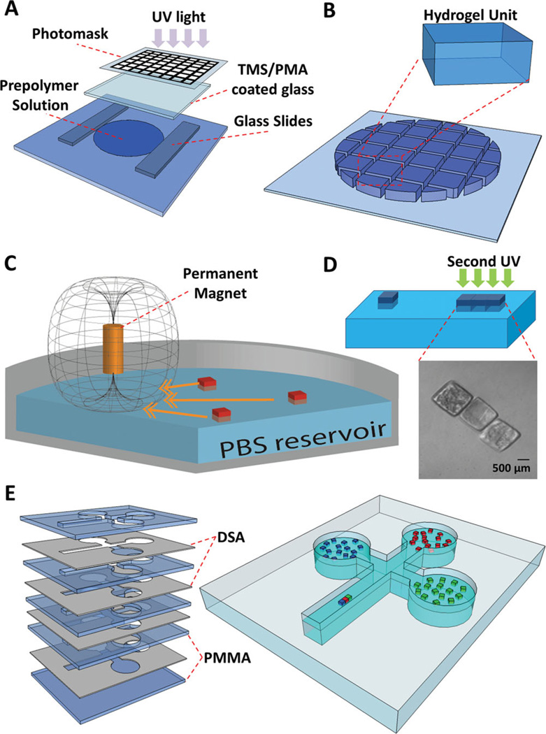
To fabricate microscale hydrogels of different sizes, photo-crosslinkable hydrogel precursor solution was placed between spacers on a glass slide (Figure 1A). Hydrogels were formed by exposing the gel precursor solution to UV light. Hydrogels of different sizes (200 × 200 × 150 µm3, 400 × 400 × 150 µm3, 500 × 500 × 150 µm3, and 1000 × 1000 × 150 µm3) were fabricated and kept in PBS (Figure 1B). To manipulate and assemble the hydrogels, a cylindrical permanent magnet (NdFeB) was placed above the liquid surface (Figure 1C). Hydrogels were assembled by the magnetic field followed by a secondary crosslinking to stabilize the resulting assembled gels (Figure 1D).
Figure 1.
(A) Schematic of hydrogel fabrication process. Hydrogel units were fabricated by photolithography. 20 µL of gel precursor solution was pipetted onto a glass slide and then exposed to UV light (500 mW; at a height of 50 mm above the gels) for 20 seconds. (B) We used four types of photomasks with square patterns of different sizes (200 × 200 × 150 µm3, 400 × 400 × 150 µm3, 500 × 500 × 150 µm3, and 1000 × 1000 × 150 µm3) (C) Schematic diagram of hydrogel assembly process. After fabrication, hydrogels were transferred into a petri dish containing Phosphate-Buffered Saline (PBS), and magnetic field was applied. (D) Hydrogels were assembled into different shapes. The assembly was subsequently stabilized by a secondary crosslinking step. Phase image of assembled hydrogels were shown. (E) Fabrication of a celtic-shaped fluidic patterning chamber using multiple layers of thin poly-methyl methacrylate (PMMA) and double sided adhesive (DSA) sheets. The designed system is a fluidic chamber composed of three circular peripheral wells all connected to the primary rectangular well, where the assembly takes place.
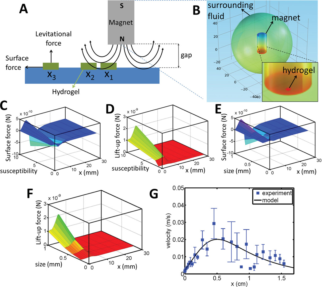
We have developed a mechanistic model to recapitulate the motion of a hydrogel exposed to a magnetic field (Movie S1). This principle sets the basis of paramagnetic assembly approach described. We developed a multi-step computational and mathematical model (Figure 2A and 2B) to investigate the effects of the following parameters on hydrogel motion in a magnetic field: (1) hydrogel susceptibility (Figure 2C and 2D), (2) hydrogel size (Figure 2E and 2F), and (3) distance between hydrogels and magnet (Figure S1A and S1B). To calculate magnetic forces on a hydrogel, we solved Maxwell equations using finite-difference method. The computational model included a cylindrical magnet and a hydrogel in liquid medium (Figure 2B). In this model, the surrounding medium was set sufficiently large such that the magnetic field was tangential along the boundaries (Table S2). This condition was satisfied by the requirement of closed loops around the magnet (n · B = 0), where n is unit vector normal to the surface, and B is the magnetic flux density. As a constitutive equation for the hydrogel and the surrounding air, B = µ0µrH is employed. Here, H is the magnetic field density, µ0 is the permeability of free space (4π · 10−7 N · A−2), and µr is the relative permeability coefficient. Simulation results showed that as the hydrogel size and susceptibility increased, magnetic forces such as levitational forces (i.e., vertical to the direction of motion) and surface forces (i.e., along the direction of motion) increased (Figure 2C–F). Decreasing the gap between the magnet and the hydrogel enhanced magnetic force amplitude on the hydrogel (Figure S1A and S1B).
Figure 2.
(A) Schematic for the motion of a hydrogel (1 mm × 1 mm × 200 µm) under a magnetic field. (B) Contour plot of magnetic potential. (C) Surface and (D) Levitational magnetic forces as a function of hydrogel susceptibility and horizontal “x” location. (E) Surface and (F) Levitational magnetic forces as a function of characteristic length of a hydrogel and horizontal “x” location. (G) Validation of hydrogel motion as a function of time (squares represent experimental data (n = 10) and solid line represents the model fit).
We developed a mathematical model to describe the motion of a hydrogel moving on a linear path towards the magnet (in x-direction):
| (1) |
where Fm is the magnetic force exerted by a permanent magnet and Fd is the drag force exerted by the fluid environment. The first term in Equation (1) stands for inertial force on the hydrogel. The dependent parameters are acceleration (ẍ (t)) and velocity (ẋ (t)) of the hydrogel. Here, x′ is relative location of magnet with respect to the hydrogel:
| (2) |
where, vm is the magnet velocity.
Magnetic forces were calculated using a computational model (Figure 2C–F), and incorporated into the mathematical model using sixth-order Gaussian fits:
| (3) |
where ai, bi, and ci for i = 1, 2, 3, 4, 5, and 6 are the coefficients of the Gaussian fit. Drag force exerted on the hydrogel was approximated with Stokes’ drag equation due the small Reynolds number of the system:
| (4) |
where µ is the viscosity of the PBS, R is length scale of the hydrogel. Here, we chose the characteristic length scale as the side length of a square-shaped hydrogel. Substituting Equations (2), (3), and (4) into Equation (1) leading to the final model equation:
| (5) |
To compare the experimental and theoretical (Equation 5) results, we recorded and quantified the motion of a hydrogel under a magnetic field (Movie S1). Recorded images were processed by an image processing software (ImageJ with MTrackJ plugin, National Institutes of Health (NIH)) to extract the kinematic parameters from the hydrogel motion. Resulting dependence of hydrogel velocity on hydrogel location relative to the magnet was validated by the mathematical model as in Equation (5). Here, we fixed the magnet location (vm = 0) at x = 0, and placed a hydrogel few millimeters away from the magnet (initial conditions: x(t = 0) = 25 mm, ẋ(t = 0) = 0). We compared experimental and numerical velocities of a hydrogel as a function of time. We have observed a statistically significant agreement between the mathematical model and the experimental results (Figure 2G). According to the model prediction as well as the experimental observations, the hydrogel initially accelerated towards the magnet. Then, it slowed down as the horizontal component of the magnetic force decreased while the gel moved closer to and below the magnet (Figure 2G). Finally, when the fluidic drag force overcame the magnetic force, the hydrogel stopped. This phenomenon was repeatedly observed for multiple hydrogels, which were assembled into 3D structures (Figure 3).
Figure 3.
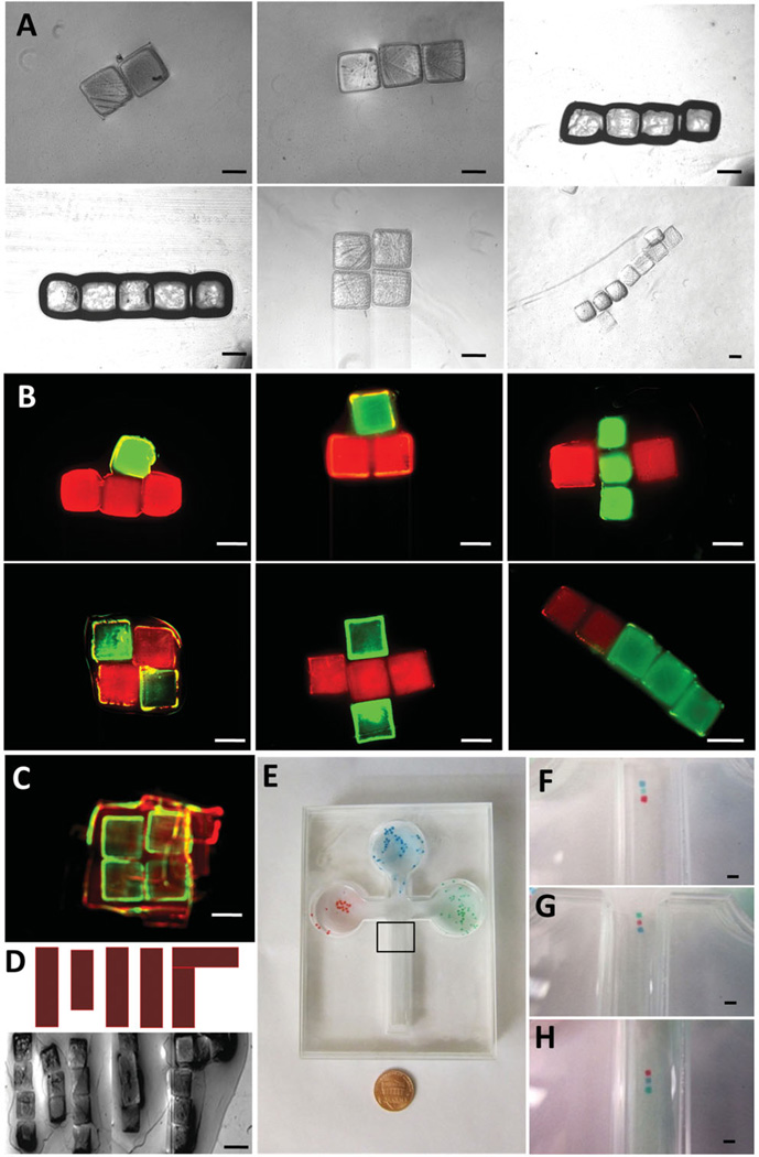
(A) Phase images of structural hydrogel assemblies. Scale bar is 500 µm. (B) Assembled hydrogels with FITC-dextran and Rhodamine B. Green and red labeled hydrogels were assembled indicating control over the assembled constructs. (C) Hydrogels can be magnetically directed to form 3D constructs. These multi-layer 3D constructs were fabricated by stacking layers. Merged fluorescent image of layer-by-layer 3D assembly (First layer of gels were stained with Rhodamine-B; second layer of gels were stained with FITC-dextran; third layer of gels were stained with Rhodamine-B). (D) Assembled hydrogels of a complex shape. (E) Celtic-shaped patterning chamber and a penny. Each well is a reservoir for red, blue, or green hydrogels. Linear shape assembled hydrogels with red gel at the front (F), in the middle (G), at the back (H). The black rectangle marks the assembly location (zoomed images after assembly in F, G, and H). Scale bar is 1 mm for (C–H).
We assembled hydrogels on-demand into different geometrical shapes using the principles described above (Figure 3A). Fluorescence images of assembled hydrogels with FITC-dextran and Rhodamine B of different geometries such as plus, square, and rod shapes were shown (Figure 3B). Also, hydrogels were assembled to form 3D constructs (Figure 3C). 2D square-shaped assemblies were placed layer-by-layer forming a 3D construct (Figure 3C). The first layer of the assembly was stained with Rhodamine-B, second layer of the assembly was stained with FITC-dextran, and the third layer was stained with Rhodamine-B. To illustrate control over assembled structures, we patterned gels into complex shapes such as the letters “MIT” by directing hydrogels step-by-step via magnetic fields (Figure 3D). To further demonstrate the assembly capabilities of the technology integrated with a microfluidic platform, a celtic-shaped fluidic chamber was fabricated (Figure 1E and 3E). Each compartment of the chamber was used as a reservoir for a different color stained hydrogel (red, blue, and green). These hydrogels were pulled out of their individual reservoirs by manually moving the magnets and assembled on-demand into hydrogel sequences: red gel at the front (Figure 3F), red gel in the middle (Figure 3G), red gel at the end (Figure 3H).
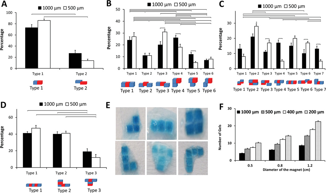
We have statistically analyzed the assembled hydrogels with respect to their assembled shapes and geometries (Figure 4). Percentages of the assembled shapes were determined for (A) two-gel, (B) three-gel, (C) four-gel, and (D) five-gel combinations. We assessed the effect of assembly on different configurations for two different hydrogel sizes, i.e., 500 µm × 500 µm × 150 µm and 1000 µm × 1000 µm × 150 µm. For two-gel combinations, over 90% of the gels were assembled without misalignment (size = 500 µm, Figure 4A). Statistically significant difference in percentages of assembly types (p < 0.05) was observed between different gel sizes (Figure 4A). Three-gel combinations mostly resulted in linear rod-shaped assembly (type 1), and misaligned linear rod-shaped assemblies (Figure 4B, type 3 and 4). There was a statistically significant difference (p < 0.05) between the two hydrogel sizes in type 3, 4 and 5 assemblies (Figure 4B). For the case of four-gel assembly, we observed square-shaped and linear-shaped assemblies (Figure 4C). There was a statistically significant difference (p < 0.05) in assembled shapes between the two hydrogel sizes for assembled types 3, 4, 6, and 7. For five-gel combinations, half of the assemblies had a linear rod-shaped structure (Figure 4D). We observed that hydrogel size had no effect on the assembled types. Typical assembly images of different types were demonstrated in Figure 4E. To investigate the effects of magnet size on assembly, we used a range of magnet sizes, i.e., magnet diameters were 0.5, 0.8, and 1.2 cm (Figure 4F). As the magnet size increased, the exposure area of the magnetic field was larger and the number of assembled hydrogels increased. Similarly, as the hydrogel size decreased from 1000 µm × 1000 µm × 150 µm to 200 µm × 200 µm × 150 µm, a larger number of hydrogels were assembled (Figure 4F). Gels with and without dyes moved with similar kinematic characteristics.
Figure 4.
Characterization of assembled hydrogels. Percentages of resulting assemblies were plotted for (A) two-gel, (B) three-gel, (C) four-gel, and (D) five-gel combinations. These experiments were performed for two hydrogel sizes: 500 µm × 500 µm × 150 µm and 1000 µm × 1000 µm × 150 µm. Brackets connecting groups indicate statistically significant difference (n = 4, p < 0.05). “*” indicates statistically significant difference between all other groups. Error bars represent standard error of the mean. (E) Assembled hydrogels in different shapes. (F) Effect of magnet size on number of assembled hydrogels for different hydrogel sizes: 200 µm × 200 µm × 150 µm, 400 µm × 400 µm × 150 µm, 500 × 500 × 150 µm, and 1000 µm × 1000 µm × 150 µm. Brackets connecting groups indicate statistically significant difference (n = 8, p < 0.05). Error bars represent standard error of the mean.
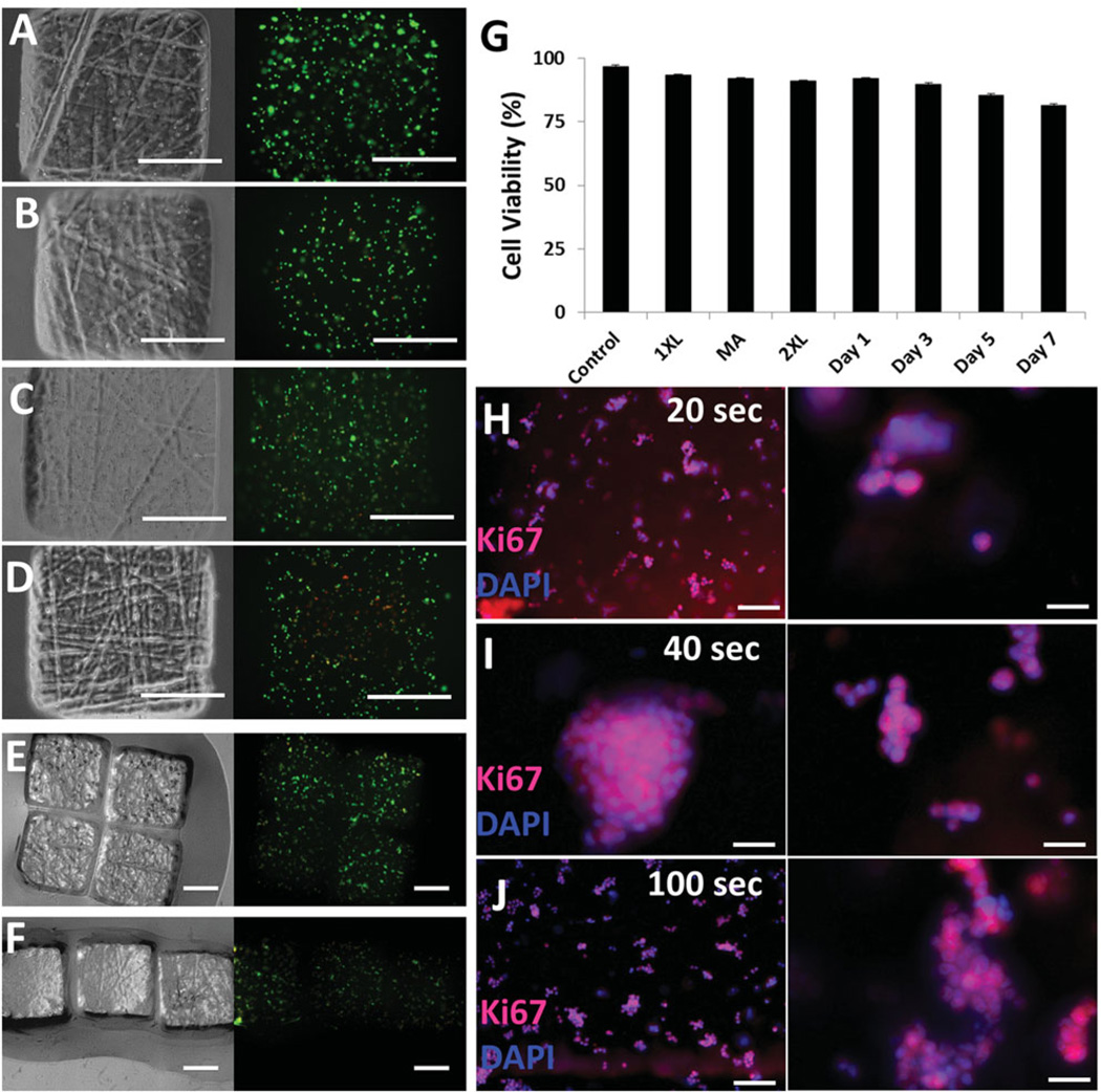
To evaluate cell viability, we encapsulated NIH 3T3 cells in hydrogels (Figure 5). Phase-contrast and fluorescence images of cells encapsulated in hydrogels were shown at t = 24 h, t = 48 h, t = 72 h, t = 168 h (Figure 5 A, B, C, and D, respectively). For assembled hydrogels (Figure 5E and 5F), green represented live cells and red represented dead cells. We quantified cell viability after each step during hydrogel fabrication and assembly (Figure 5G). Within the initial 24 h, cell viabilities in hydrogels and in 2D monolayer culture controls were 92%. After the first crosslinking step, magnetic assembly, the second crosslinking step, and culture up to 7 days, cell viabilities remained above 82% (Figure 5G). Proliferation of cells has been earlier reported for high molecular weight PEG.[41] To show proliferation capacity of encapsulated cells in hydrogels, we have performed immunocytochemistry (ICC) at day 10. Cells in PEG hydrogels were stained with Ki67 (Abcam) nuclear proliferation specific marker.[42] All experimental conditions were Ki67 positive indicating that encapsulated cells were proliferating after 10 days (Figure 5 H–J).
Figure 5.
Cell viability in hydrogels. Phase contrast and fluorescence images of NIH 3T3 cell encapsulating hydrogels at time points after fabrication: (A) t = 24h, (B) t = 48h, (C) t = 72 h, and (D) t = 168h. (E and F) Phase-contrast and fluorescence images of cell encapsulating assembled hydrogels. Green represents live cells and red represents dead cells. (G) Quantification of cell viability after each step to form hydrogels. XL, 2XL, and MA stand for crosslinking, second crosslinking, and magnetic assembly, respectively. Cells were cultured for seven days. Quantification of samples (n = 8) at each time point demonstrated that viability did not significantly decrease due to UV and applied magnetic field. Scale bars are 500 µm. Error bars represent standard error of the mean. (H–J) Immunocytochemistry of proliferating cells stained with Ki67 and DAPI. (H) 20 s UV photo-crosslinking, (I) 40 s UV photo-crosslinking, (J) 100 s UV photo-crosslinking. Right column images are magnification of corresponding adjacent experimental condition. Scale bars for H and J are 100 µm. Scale bar for I is 70 µm. Scale bars for the magnified images presented on the right column are 50 µm.
To investigate the magnetic response of PEG hydrogels, we performed spectroscopic and chemical analyses as a function of UV exposure time. We validated the photo-crosslinking of PEG hydrogels via Raman spectroscopy measurements (Figure S3). Then, we performed velocity analyses for the following control groups: (Control A) a PEG hydrogel irradiated considerably long time duration (100 s), (Control B) a chemically crosslinked PEG hydrogel without UV exposure, and (Control C) a chemically crosslinked PEG hydrogel exposed to UV irradiation (Figure S4). The results showed that the hydrogels that were exposed to UV for longer durations traveled towards the magnets with a higher velocity (Supporting Information Figure S4, Movie S2–4). By electron paramagnetic resonance (EPR) spectroscopy measurements, we quantified free radicals forming in hydrogels following UV exposure. We showed that the velocity analysis results are in agreement with the EPR findings (Figure S5 and S6) suggesting a role of free radicals in paramagnetic response of hydrogels.
Magnetic field and gel interactions were observed to be stronger in the presence of magnetic nanoparticles.[21] However, potential adverse effects of embedding MNPs into hydrogels for tissue engineering applications include MNP-cell interactions, agglomeration of MNPs,[43,44] and resulting fluctuations in magnetic affinities. Here, we have shown for the first time that hydrogels that are free of MNPs can be mobilized by sufficiently strong magnetic fields for controlled assembly of constructs in a fluidic environment (Movie S1). Both experimental and theoretical analyses were performed to describe paramagnetic hydrogel manipulation and assembly.
Others have fabricated ionotropic spherical hydrogels.[45] Paramagnetic metal ions (e.g., Ho3+) were used to cross-link these millimeter-scale hydrogels. These hydrogels responded to magnetic fields. Also, a correlation between the concentration of the paramagnetic cations and magnetic field gradient was given.[45] These ions can be integrated to various gel types enabling broad response to magnetic fields. Therefore, the presented assembly method is broadly applicable to other materials and hydrogels, which demonstrate a reasonably large response to a magnetic field that can overcome the drag forces in the surrounding medium. In our experiments, we worked with polyethylene glycol (PEG) due to its biocompatibility[46] and ease-of-use during hydrogel fabrication through a photo-crosslinking step.
Since the magnetic field spans a certain area in the fluidic reservoir, we assembled gels in a large reservoir at varying locations. This limitation was addressed by creating microfluidic assembly chambers (Figure 1E and 3E), where the magnetically directed hydrogels were assembled within a controlled space at a specific location allowing improved spatial control. An alternative scalable approach is to create multiple high magnetic field locations in the same reservoir to assemble multiple constructs simultaneously.
An alternative to employing permanent magnets could be alternating current (AC)-based magnetic fields. Control via AC can be useful as long as biocompatibility of AC magnetic fields is validated and an upper limit of magnetic fields is evaluated for specific applications. On the other hand, depending on the intensity, exposure of electromagnetism on hydrogels due to AC magnetic fields need to be evaluated to avoid accumulation of thermal energy inside gels (magnetic hyperthermia)[36] leading to disassembly. Since the presented method exposes the hydrogels to relatively low intensity fields using permanent magnets, we did not experience such adverse effects. Magnetic field-induced particle control via permanent magnets is potentially simpler, inexpensive, and a promising technique for biomicrofluidics applications. These magnetic technologies do not need any electrical power, and is composed of an inexpensive permanent neodymium magnet.
In summary, the presented approach provides temporal and spatial control to manipulate and assemble hydrogels in magnetic fields using permanent magnets. The methodology developed here demonstrates a simple way of engineering 3D constructs without requiring complex peripheral equipment or magnetic nanoparticles. Exploiting magnetic properties of hydrogels enables assembly and manipulation of hydrogels without integrating them with other magnetic components such as magnetic nanoparticles. A high level of control over hydrogel assembly can benefit from superposed magnetic features of hydrogels and different types of cells. This new direction opens a new vista in the context of manipulation and patterning by differentiating the individual or composite structures with respect to their magnetic properties. The assembly methodology developed here can find broad applications in areas such as regenerative medicine, microphysiological system engineering, pharmaceutical research, biological research, and space sciences (e.g., to mimic microgravity environments for cellular events).
Supplementary Material
Acknowledgements
We thank Dr. Metin Sitti, Dr. Eda Ayse Aksoy, Eric Diller, and Paul Avishek for helpful discussions. We would like to acknowledge NIH R21-HL112114 and R21-HL095960. This material is based in part upon work supported by the National Science Foundation under NSF CAREER Award Number 1150733. Any opinions, findings, and conclusions or recommendations expressed in this material are those of the author(s) and do not necessarily reflect the views of the National Science Foundation.
Footnotes
Supporting Information
Supporting Information is available from the Wiley Online Library or from the author.
References
- 1.Abrahamsson CK, Yang F, Park H, Brunger JM, Valonen PK, Langer R, Welter JF, Caplan AI, Guilak F, Freed LE. Tissue Eng. Part A. 2010;16:3709. doi: 10.1089/ten.tea.2010.0190. [DOI] [PMC free article] [PubMed] [Google Scholar]
- 2.Engelmayr GC, Cheng MY, Bettinger CJ, Borenstein JT, Langer R, Freed LE. Nat. Mater. 2008;7:1003. doi: 10.1038/nmat2316. [DOI] [PMC free article] [PubMed] [Google Scholar]
- 3.Langer R, Vacanti JP. Science. 1993;260:920. doi: 10.1126/science.8493529. [DOI] [PubMed] [Google Scholar]
- 4.Mironov V, Visconti RP, Kasyanov V, Forgacs G, Drake CJ, Markwald RR. Biomaterials. 2009;30:2164. doi: 10.1016/j.biomaterials.2008.12.084. [DOI] [PMC free article] [PubMed] [Google Scholar]
- 5.Liu Tsang V, Chen AA, Cho LM, Jadin KD, Sah RL, DeLong S, West JL, Bhatia SN. Faseb J. 2007;21:790. doi: 10.1096/fj.06-7117com. [DOI] [PubMed] [Google Scholar]
- 6.Xia XX, Xu Q, Hu X, Qin G, Kaplan DL. Biomacromolecules. 2011;12:3844. doi: 10.1021/bm201165h. [DOI] [PMC free article] [PubMed] [Google Scholar]
- 7.Park JH, Chung BG, Lee WG, Kim J, Brigham MD, Shim J, Lee S, Hwang CM, Durmus NG, Demirci U, Khademhosseini A. Biotechnol. Bioeng. 2010;106:138. doi: 10.1002/bit.22667. [DOI] [PMC free article] [PubMed] [Google Scholar]
- 8.Langer R. Tissue Eng. Part A. 2007;13:1. doi: 10.1089/ten.2006.0219. [DOI] [PubMed] [Google Scholar]
- 9.Alsberg E, Anderson KW, Albeiruti A, Franceschi RT, Mooney DJ. J. Dent. Res. 2001;80:2025. doi: 10.1177/00220345010800111501. [DOI] [PubMed] [Google Scholar]
- 10.Popa EG, Gomes ME, Reis RL. Biomacromolecules. 2011;12:3952. doi: 10.1021/bm200965x. [DOI] [PubMed] [Google Scholar]
- 11.Vemula PK, Boilard E, Syed A, Campbell NR, Muluneh M, Weitz DA, Lee DM, Karp JM. J. Biomed. Mater. Res. A. 2011;97:103. doi: 10.1002/jbm.a.33020. [DOI] [PubMed] [Google Scholar]
- 12.Fischbach C, Chen R, Matsumoto T, Schmelzle T, Brugge JS, Polverini PJ, Mooney DJ. Nat. Methods. 2007;4:855. doi: 10.1038/nmeth1085. [DOI] [PubMed] [Google Scholar]
- 13.Jakab K, Norotte C, Marga F, Murphy K, Vunjak-Novakovic G, Forgacs G. Biofabrication. 2010;2:14. doi: 10.1088/1758-5082/2/2/022001. [DOI] [PMC free article] [PubMed] [Google Scholar]
- 14.Tibbitt MW, Anseth KS. Biotechnol. Bioeng. 2009;103:655. doi: 10.1002/bit.22361. [DOI] [PMC free article] [PubMed] [Google Scholar]
- 15.Kenar H, Kose GT, Hasirci V. J. Mater. Sci. - Mater. Med. 2010;21:989. doi: 10.1007/s10856-009-3917-8. [DOI] [PubMed] [Google Scholar]
- 16.Duarte ARC, Mano JF, Reis RL. J. Supercritical Fluids. 2010;54:282. [Google Scholar]
- 17.Du Y, Lo E, Ali S, Khademhosseini A. Proc. Natl. Acad. Sci. USA. 2008;105:9522. doi: 10.1073/pnas.0801866105. [DOI] [PMC free article] [PubMed] [Google Scholar]
- 18.Sekeroglu K, Gurkan UA, Demirci U, Demirel MC. Appl. Phys. Lett. 2011;99:3. doi: 10.1063/1.3625430. [DOI] [PMC free article] [PubMed] [Google Scholar]
- 19.Xu F, Finley TD, Turkaydin M, Sung Y, Gurkan UA, Yavuz AS, Guldiken RO, Demirci U. Biomaterials. 2011;32:7847. doi: 10.1016/j.biomaterials.2011.07.010. [DOI] [PMC free article] [PubMed] [Google Scholar]
- 20.Xu F, Moon SJ, Emre AE, Turali ES, Song YS, Hacking SA, Nagatomi J, Demirci U. Biofabrication. 2011;2:9. doi: 10.1088/1758-5082/2/1/014105. [DOI] [PubMed] [Google Scholar]
- 21.Xu F, Wu CAM, Rengarajan V, Finley TD, Keles HO, Sung YR, Li BQ, Gurkan UA, Demirci U. Adv. Mater. 2011;23:4254. doi: 10.1002/adma.201101962. [DOI] [PMC free article] [PubMed] [Google Scholar]
- 22.Gurkan U, Tasoglu S, Kavaz D, Demirel M, Demirci U. Adv. Healtcare Mater. 2012;1:149. doi: 10.1002/adhm.201200011. [DOI] [PMC free article] [PubMed] [Google Scholar]
- 23.McGuigan AP, Leung B, Sefton MV. Nat. Protocols. 2006;1:2963. doi: 10.1038/nprot.2006.443. [DOI] [PubMed] [Google Scholar]
- 24.Tsang VL, Bhatia SN. Adv. Biochem. Eng. Biotechnol. 2007;103:189. doi: 10.1007/10_010. [DOI] [PubMed] [Google Scholar]
- 25.Griffith LG, Swartz MA. Nat. Rev. 2006;7:211. doi: 10.1038/nrm1858. [DOI] [PubMed] [Google Scholar]
- 26.Abbott A. Nature. 2003;424:870. doi: 10.1038/424870a. [DOI] [PubMed] [Google Scholar]
- 27.Pampaloni F, Reynaud EG, Stelzer EH. Nat. Rev. Mol. Cell Biol. 2007;8:839. doi: 10.1038/nrm2236. [DOI] [PubMed] [Google Scholar]
- 28.Bryant SJ, Cuy JL, Hauch KD, Ratner BD. Biomaterials. 2007;28:2978. doi: 10.1016/j.biomaterials.2006.11.033. [DOI] [PMC free article] [PubMed] [Google Scholar]
- 29.Hahn MS, Taite LJ, Moon JJ, Rowland MC, Ruffino KA, West JL. Biomaterials. 2006;27:2519. doi: 10.1016/j.biomaterials.2005.11.045. [DOI] [PubMed] [Google Scholar]
- 30.Pampaloni F, Reynaud EG, Stelzer EHK. Nat. Rev. 2007;8:839. doi: 10.1038/nrm2236. [DOI] [PubMed] [Google Scholar]
- 31.Frasca G, Gazeau F, Wilhelm C. Langmuir. 2009;25:2348. doi: 10.1021/la8030792. [DOI] [PubMed] [Google Scholar]
- 32.Yellen BB, Hovorka O, Friedman G. Proc. Natl. Acad. Sci. USA. 2005;102:8860. doi: 10.1073/pnas.0500409102. [DOI] [PMC free article] [PubMed] [Google Scholar]
- 33.Kose AR, Fischer B, Mao L, Koser H. Proc. Natl. Acad. Sci. USA. 2009;106:21478. doi: 10.1073/pnas.0912138106. [DOI] [PMC free article] [PubMed] [Google Scholar]
- 34.Krebs MD, Erb RM, Yellen BB, Samanta B, Bajaj A, Rotello VM, Alsberg E. Nano Lett. 2009;9:1812. doi: 10.1021/nl803757u. [DOI] [PMC free article] [PubMed] [Google Scholar]
- 35.Souza GR, Molina JR, Raphael RM, Ozawa MG, Stark DJ, Levin CS, Bronk LF, Ananta JS, Mandelin J, Georgescu MM, Bankson JA, Gelovani JG, Killian TC, Arap W, Pasqualini R. Nat. Nanotechnol. 2010;5:291. doi: 10.1038/nnano.2010.23. [DOI] [PMC free article] [PubMed] [Google Scholar]
- 36.Le Renard PE, Jordan O, Faes A, Petri-Fink A, Hofmann H, Rufenacht D, Bosman F, Buchegger F, Doelker E. Biomaterials. 2010;31:691. doi: 10.1016/j.biomaterials.2009.09.091. [DOI] [PubMed] [Google Scholar]
- 37.Mirica KA, Ilievski F, Ellerbee AK, Shevkoplyas SS, Whitesides GM. Adv. Mater. 2011;23:4134. doi: 10.1002/adma.201101917. [DOI] [PubMed] [Google Scholar]
- 38.Pankhurst Q, Connolly J, Jones SK, Dobson J. J. Phys. D. 2003;36:R167. [Google Scholar]
- 39.Alsberg E, Feinstein E, Joy MP, Prentiss M, Ingber DE. Tissue Eng. Part A. 2006;12:3247. doi: 10.1089/ten.2006.12.3247. [DOI] [PubMed] [Google Scholar]
- 40.Xu F, Inci F, Mullick O, Gurkan UA, Sung Y, Kavaz D, Li B, Denkbas EB, Demirci U. ACS Nano. 2012;6:6640. doi: 10.1021/nn300902w. [DOI] [PMC free article] [PubMed] [Google Scholar]
- 41.Bharadwaj S, Vishnubhotla R, Shan S, Chauhan C, Cho M, Glover SC. Biomed. Biotechnol. 2011 doi: 10.1155/2011/587470. 2011. [DOI] [PMC free article] [PubMed] [Google Scholar]
- 42.Kee N, Sivalingam S, Boonstra R, Wojtowicz JM. J. Neuroscience Methods. 2002;115:97. doi: 10.1016/s0165-0270(02)00007-9. [DOI] [PubMed] [Google Scholar]
- 43.Wang Y, Li B, Zhou Y, Jia D. Polym. Adv. Technol. 2008;19:1256. [Google Scholar]
- 44.Xia H-B, Yi J, Foo P-S, Liu B. Chem. Mater. 2007;19:4087. [Google Scholar]
- 45.Winkleman A, Bracher PJ, Gitlin I, Whitesides GM. Chem. Mater. 2007;19:1362. doi: 10.1021/cm062626f. [DOI] [PMC free article] [PubMed] [Google Scholar]
- 46.Bjugstad KB, Redmond DE, Jr, Lampe KJ, Kern DS, Sladek JR, Jr, Mahoney MJ. Cell Transplantation. 2008;17:409. [PubMed] [Google Scholar]
- 47.Gurkan UA, Fan Y, Xu F, Erkmen B, Urkac ES, Parlakgul G, Bernstein J, Xing W, Boyden ES, Demirci U. Adv. Mater. 2012 doi: 10.1002/adma.201203261. [DOI] [PMC free article] [PubMed] [Google Scholar]
- 48.Tasoglu S, Demirci U. Trends Biotechnol. 2012 doi: 10.1016/j.tibtech.2012.10.005. http://dx.doi.org/10.1016/j.tibtech.2012.10.005. [DOI] [PMC free article] [PubMed] [Google Scholar]
Associated Data
This section collects any data citations, data availability statements, or supplementary materials included in this article.


