Abstract
A digital light projector is implemented as an integrated illumination source and scanning element in a confocal non-mydriatic retinal camera, the DLP-Cam. To simulate scanning, a series of illumination lines are rapidly projected on the retina. The backscattered light is imaged onto a 2-dimensional rolling shutter CMOS sensor. By temporally and spatially overlapping the illumination lines with the rolling shutter, confocal imaging is achieved. This approach enables a low cost, flexible, and robust design with a small footprint. Qualitative image comparison with commercial non-mydriatic SLOs and fundus cameras shows comparable fine vessel visibility and contrast.
Keywords: DLP-Cam, LightCrafter, rolling shutter, DLP, CMOS, spatial light modulator, confocal imaging, digital imaging, biomedical imaging
1. INTRODUCTION
Confocal imaging is a well-known imaging technique in which light returning from a target is spatially filtered prior to detection. Spatial filtering is commonly used to reduce image artifacts, improve image contrast, and isolate features of interest, which has helped popularize it for biomedical imaging applications.
Laser scanning confocal imaging systems traditionally illuminate a target with a point or line that is rapidly scanned across the field of view. The light returning from the target is descanned and directed through an aperture to a photosensitive detector. By synchronizing the scanning with the exposure timing of the detector, a two-dimensional image of the target is constructed. Adjustments to the aperture position, shape, and size allow a user to trade off the amount of spatial filtering with the amount of light returning from the target that is detected.
An alternate approach to laser scanning confocal imaging makes use of the rolling shutter method of detection that is common to complementary metal oxide semiconductor (CMOS) sensor chips1–3. Unlike a global shutter, which integrates charge evenly across the entire active sensor area during the exposure time, the rolling shutter integrates light over one or more pixel rows at a time, spanning a “shutter width.” During each frame, the rolling shutter progressively scans across the active sensor region with a shutter width related to the total frame exposure time. Light incident on the sensor outside the active rolling shutter read area is not captured, and therefore cannot reduce contrast.
The rolling shutter means of detection has historically been criticized for its performance when imaging moving targets and using short exposure times, which can cause wobble, skew, smear, and partial exposure. However, these detection characteristics can also be used to one’s advantage, for example, in pose recovery motion algorithms4 and line-scanning confocal retinal imaging5, 6. To perform confocal imaging with the rolling shutter, a target is illuminated with a line that is scanned across the field of view. Rather than descanning the light returning from the target, it is imaged directly onto a 2D CMOS pixel array. The position of the line focused on the target is matched to the position of the rolling shutter throughout the frame exposure. With spatial filtering provided by a narrow shutter width, directly backscattered light is preferentially detected, while out-of-focus and multiply scattered light is rejected.
A benefit of confocal imaging using the rolling shutter is that it allows adjustments to the shutter position and width in pixel increments on a frame-to-frame basis. Compared with mechanical apertures, the rolling shutter allows much more precise and rapid changes to the spatial filter function since it is electronically controlled in real-time.
The Laser Scanning Digital Camera (LSDC) is a line-scanning camera that uses the rolling shutter to obtain confocal images of the retina for cost-effective diabetic retinopathy screening and visual function measurements7–9. By offsetting the rolling shutter position with respect to the illumination line, the imaging system can rapidly switch to a dark-field imaging mode, which has been used to detect scattering defects in the deeper retina that are normally masked by scattering in the superficial retina10.
The rolling shutter spatial filter has also been demonstrated as an optical frequency filter when a dispersive element is added to the detection pathway. In this case, the rolling shutter is matched to a particular wavelength of light returning from the target. The shutter width controls the spectral bandwidth that is detected while its starting position adjusts the center wavelength. When applied to fluorescence imaging, the spectral components of the fluorescent emission from the target can be selectively isolated and imaged11.
To perform confocal imaging, the LSDC requires a laser illumination source and galvanometer scanning element to deliver light onto the retina. The present technique has been developed in which the source and scanning element required in laser scanning confocal systems are substituted for a handheld digital light projector (DLP)12,13. The DLP uses a choice of high power red, green, and blue light emitting diodes (LEDs) to illuminate a digital micromirror array that is located at a conjugate target plane. To simulate line-scanning, the DLP is programmed to rapidly project a series of narrow adjacent lines, which are matched to the position of the sensor’s rolling shutter during a frame exposure. Confocal imaging using a DLP illumination source has been demonstrated for retinal imaging, dual-wavelength and fluorescence imaging, and for Fourier domain optical coherence tomography13–16.
The combination of the spatial light modulation of a DLP with the spatial filtering provided by the rolling shutter of a CMOS sensor permits a cost effective and compact implementation of a confocal imaging system. The fact that the DLP can be used as a source without hardware modification and can be driven directly from software reduces electronic complexity while allowing for more versatile illumination geometries than that provided by a pair of scanning mirrors.
In this work, the second generation of the DLP-Cam retinal camera is presented, shown in Figure 1. Improvements over prior work include the use of a newer DLP (LightCrafter, Texas Instruments Inc., Dallas, TX) which is handheld and provides greater illumination power and pattern projection speed, greater timing synchronization and stability. Combined with a new CMOS sensor (MT9P031, Aptina Imaging Corp., San Jose, CA), which can be controlled directly from its hardware registers, and an improved optical design, the second generation DLP-Cam performs real-time non-mydriatic retinal imaging at 27.3 Hz with a 33 × 25 deg. retinal field of view.
Figure 1.
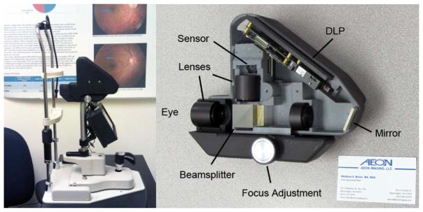
Left: The DLP-Cam installed at a community clinic site in California. The DLP-Cam uses a 7″ touchscreen LCD screen and single-board computer, and attaches to a standard slit lamp base.
Right: The DLP-Cam enclosure, built with a 3D printer, uses press-fit grooves for simple and fast optical component placement. Fine alignment of the illumination field of view and sensor region of interest is performed through software. Mirror immediately prior to sensor removed for clarity. A standard 3.5″ × 2″ business card is shown for scale.
2. METHODOLOGY
The second generation DLP-Cam uses the LightCrafter DLP released in 2012, which has a 608×684 digital micromirror resolution and a 3 channel 8-bit red, green, and blue LED output. To simulate line-scanning, the LightCrafter projects a series of adjacent rectangular lines in rapid progression that are timed and spatially located according to the position of the CMOS rolling shutter. In order to project illumination lines at a sufficient speed for real-time imaging, the LightCrafter is run in its structured illumination mode. In this configuration, a series of 96 monochrome illumination lines are pre-loaded into a ring-buffer in the DLP’s memory and displayed with a maximum pattern projection rate of 4 kHz. The projected line patterns are externally triggered by a factor of the MT9P031 CMOS sensor line signal.
The spectrum of the LightCrafter’s white-light output, shown in Figure 2, was measured with a USB4000-VIS-NIR spectrometer (Ocean Optics, Inc., Dunedin, FL, USA). The three peaks show, from left to right, the spectrum from the blue, green and red LED channels, respectively. Each line pattern is displayed for just 300 μsec in order to limit unnecessary exposure of the retina. The blue LED channel is not used for retinal imaging due to ocular safety considerations and patient comfort.
Figure 2.
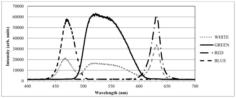
Optical spectrum of Texas Instruments’ LightCrafter DLP. The three peaks show, from left to right, the output of the blue, green, and red DLP channels, respectively.
The 5 megapixel monochrome CMOS sensor used in this study was set to operate with a region of interest of 2048×1536 (standard 3 megapixel format), with 2× binning. In this configuration, the sensor’s line-valid signal undergoes 768 square-wave periods per frame. By dividing the line signal by 8 and using it to trigger the DLP, the DLP patterns are temporally synchronized to the rolling shutter read-out, with all 96 pre-loaded illumination patterns projected every frame. The sensor’s frame-valid signal is used to match the start of a sensor frame to the first projected DLP pattern in the sequence. Once temporally synchronized, the rolling shutter width and row offset can be adjusted through software in real-time, allowing fine spatial calibration between the illumination lines and rolling shutter position.
The use of the LightCrafter DLP and rolling shutter method of detection enables a simple free-space optical design for retinal imaging, shown in Figure 1 Right. The projected light from the DLP is collimated, polarized, and then focused by an ocular lens into a subject’s pupil. A polarizing beamsplitter directs orthogonally polarized light return from the retina to a detection pathway, where it is magnified and focused onto the CMOS sensor without descanning. The use of polarized light reduces unwanted stray light and reflections from optical components from reaching the detector, while the telecentric design and spatial filtering provided by the rolling shutter help to remove unwanted reflections from the subject’s cornea. A conjugate retinal plane is located between the polarizing beamsplitter and ocular lens, which permits system calibration and optimization with a test target. Spatial synchronization is achieved by matching the sensor region of interest to the projected field of view, and by matching the starting pixel row to the first projected DLP line.
The integration of the light sources, driver, and spatial light modulator into a single DLP package reduces the cost and time required to align a separate light source and galvanometer scanner, and interface it to the rest of the imaging system. By adjusting the starting row and column of the illumination and detection regions of interest, small adjustments to the optical alignment may be made through software without the need for kinematic mounts or time-consuming manual alignment. The DLP-Cam components are enclosed in a pair of plastic mounts that were custom designed and built in-house using a 3D printer (Projet 1500, 3D Systems Inc., Rock Hill, SC). The DLP-Cam enclosure not only eliminates stray light and keeps the components protected from the environment, but also holds the optics in set locations according to the optical design. The DLP-Cam occupies a footprint of 7.6 × 6.4 × 2.9 inches and weighs 2.3 lbs.
The DLP-Cam is attached to a standard slit-lamp base for retinal imaging, shown in Figure 1 Left. The retina is illuminated using the DLP’s built-in red (centered at 630 nm) or green (centered at 540 nm) LED channels. A small input-output pupil of 1.6 mm permits non-mydriatic imaging well after a subject’s pupil has constricted. Acquired red and green image frames are registered, averaged, and overlaid in post-processing to produce a pseudo color fundus photo with a digital resolution of 1024 × 768 pixels, as shown in Figure 3.
Figure 3.
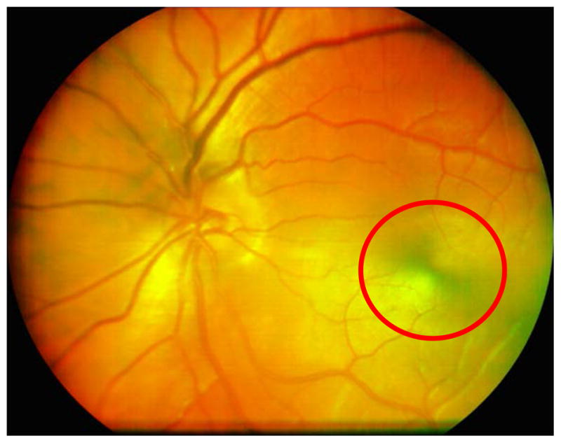
20-frame averaged pseudo color DLP-Cam image of an undilated 27 year old normal Caucasian male imaged at the Indiana University School of Optometry. The macular bow tie (circled), caused by the birefringence in Henle’s fiber layer, can help locate the fovea. Accurate foveal localization can be important for the diagnosis of vision threatening disease, as well as for repositioning small field of view devices, such as adaptive optics imaging systems.
Image acquisition is performed on a single-board computer (Beagleboard-xM, beagleboard.org) through a user interface that is displayed on a 7″ LCD touchscreen (ULCD7, BeagleBoardToys.com). Both are mounted directly behind the camera, with an optional cable connection to a standard desktop monitor. The DLP’s red channel is used as the starting illumination for imaging, which is perceived to be less bright by the subject and constricts the pupil less than the green channel. The retinal image is displayed to the operator at a rate of 17 Hz, though images may be acquired in bursts at up to 27.3 Hz. The red channel is used while the instrument is aligned to the subject’s pupil, and the focus is adjusted to compensate for refractive error. In addition to the sequence of lines, the DLP also projects a dot used to guide the subject’s fixation. The subject perceives this brighter fixation dot over a red light background. The dot is projected when the rolling shutter is displaced laterally in the retinal field; this excludes the backscattered fixation light from the image. While imaging, users may adjust the confocal aperture width and position with respect to the projected illumination line through software for each of the red and green channels independently. The sensor gain and DLP LED currents may also be adjusted to optimize the color balance of the pseudo color image. The maximum time-averaged power at the cornea is 80 μW and 110 μW for the red and green channels, respectively, though retinal images have been obtained on undilated subjects with as little as 40 μW time-averaged power per channel. With a line-illumination geometry, the maximum time-averaged powers are well-within ANSI safe exposure limits, with a safety factor greater than 20 after 10-minute continuous exposure.
The DLP-Cam illumination line width of 8 pixels at the sensor is limited by a combination of the speed of the DLP, and the desired sensor frame rate and pixel resolution. The width of the rolling shutter was set to 32 pixels, which provides a good trade-off between the amounts of spatial filtering (perceived by retinal vessel contrast) and light detected. With the illumination line width equal to one-quarter the rolling shutter width, the projected lines closely approximate a continuous line scanning system.
3. RESULTS
A sample 20-frame averaged pseudo color retinal image of an undilated 27 year old male Caucasian subject is shown in Figure 3. Due to the DLP-Cam’s polarization sensitive detection and the birefringence present in Henle’s fiber layer, a circular intensity variation in the macula, called the macular cross, is visible in images of the healthy retina. Accurate localization of the fovea can be helpful, particularly with respect to the location of retinal lesions when diagnosing treatment for retinal disease. The macular cross can also provide a useful landmark for adaptive optics imaging systems, which acquire high magnification retinal images over small (2–3 deg) fields of view at a specific retinal location of interest that is determined a priori.
The sample image shown in Figure 3 is comprised of two 20-frame buffers that were separately acquired using red and green LED illumination. The frames were registered to account for eye motion and averaged in post-processing, and then overlaid to create a color representation of the retina that is familiar to eye care professionals. A similar image set can be obtained by alternating the illumination and sensor settings (e.g. shutter width, gain, etc.) on a frame-to-frame basis. By alternating the illumination every frame, pseudo color image frame pairs are similar, which simplifies the postprocessing registration steps. Likewise, the DLP-Cam can alternate the row offset on a frame-to-frame basis, providing bright and dark field image frame pairs for differential contrast imaging. Unfortunately, the use of these alternating operating modes slows the frame rate to 7.5 Hz (per pair of image frames), which makes the imaging more susceptible to motion artifacts in patients with poor fixation stability. However, frames with excessive eye motion or image shearing can be removed in post-processing.
The DLP-Cam images of the subject in Figure 3 are qualitatively compared in Figure 4 to those obtained using 3 commercial devices: the Zeiss GDx Polarimeter, Heidelberg Spectralis SLO, and Topcon non-mydriatic fundus camera. A quantitative comparison of these images (e.g. vessel contrast) is not appropriate, primarily because the comparison commercial camera images have already been processed using unknown proprietary algorithms. However, the smallest vessels seen in the comparison images are visible with the DLP-Cam, suggesting that its resolution is sufficient to detect the subtle lesions, such as new vessel growth, that are critical in the detection of diabetic retinopathy. Qualitative image comparison shows comparable fine vessel visibility (circled region) in the DLP-Cam images.
Figure 4.

Magnified 15 × 15 deg image of a 27 year old Caucasian male using the: A. DLP-Cam (magnified from Figure 1); B. GDx Polarimeter (confocal image); C. Spectralis SLO; and D. Topcon TRC NW6S Fundus Camera. The fine vessels seen in the DLP-Cam image (encircled) indicate comparable optical resolution to the comparison cameras, including the fundus camera of the type used for DR screening. The fundus camera illumination includes short wavelengths, and macular pigment obscures the view of the fovea.
Although many eye care providers prefer color fundus photos, separate review of the red and green illumination DLP-Cam images can provide diagnostically useful information. Consistent with Elsner17, red illumination penetrates the deeper retina, providing visualization of the choroidal vasculature and detection of scattering defects in the retinal pigment epithelium, while green illumination provides a view of the superficial retina, with strong vessel contrast due to blood absorption. An example red and green image pair of a 54 year old Caucasian Hispanic female is shown in Figure 5, which illustrates the imaging differences resulting from illumination wavelength.
Figure 5.
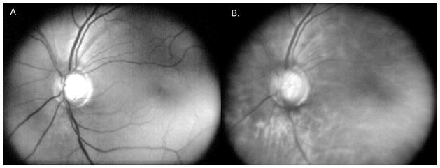
Images of a dilated 54 year old Caucasian Hispanic female recruited at the Eastmont Wellness Center community clinic in California. A. DLP-Cam averaged green illumination, showing predominantly superficial retina; B. DLP-Cam averaged red illumination image, showing features from the deeper retina.
An example dark field and differential image pair of the same patient is provided in Figure 6. The bright and dark field images were taken with a shutter width of 22 pixels, with an offset of 40 pixels. By offsetting the rolling shutter aperture, the dark field image collects predominantly multiply scattered light. The scaled difference between the bright field image of Figure 5B and dark field image of Figure 6A is shown in Figure 6B. The Michelson contrast was calculated at locations across three retinal vessels, shown by black bars in Figure 6B, in both the bright field and difference images. Proceeding from the top bar to the bottom, the Michelson contrast was 0.39, 0.09, and 0.20 for the bright field image in 5B, and 0.55, 0.12, and 0.31 for the difference image in 6B. By removing predominantly multiply scattered light, the difference image has a narrower confocal point spread function, resulting in greater image contrast. These results are consistent with Hewlett and Wilson’s subtractive confocal imaging work18.
Figure 6.
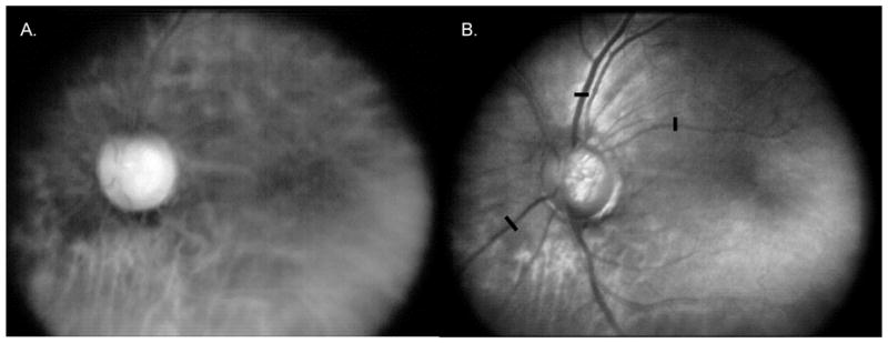
Red illumination images of the same dilated 54 year old Caucasian Hispanic female patient as in Figure 5. A. DLP-Cam averaged red illumination dark field image, showing predominantly multiply scattered light from the deeper retina; B. Scaled difference between the averaged red illumination bright field image from Figure 5B and the dark field image shown in Figure 6A. The difference image is more confocal than the bright field image in Figure 5B, with greater observed vessel and optic nerve head contrast. This is confirmed by calculating the Michelson contrast across the retinal vessels at the same three locations indicated by the black bars.
The second generation DLP-Cam was found to resolve its most significant previously reported limitations. The Texas Instruments LightCrafter DLP, as opposed to the DLP-Cam’s previously used Texas Instruments DLP v2.0 Software Development Kit, provides brighter LEDs, enabling a time-averaged power at the cornea of approximately 100 μW. Although these light levels do not pose a risk of retinal damage when used in the DLP-Cam to illuminate a wide area of the retina, further increases in illumination brightness are undesirable due to patients’ light aversion. Furthermore, the LightCrafter’s 4 kHz pre-loaded pattern display rate in its structured light illumination mode permits 96 projected lines per sensor frame when the sensor operates at 27.3 Hz. Our previously reported DLP-Cam employed 55 lines per frame at a 20 Hz sensor frame rate. An increased number of projected lines per sensor frame permit greater spatial confinement of the illumination and improved detection efficiency at narrow confocal shutter widths. Finally, the LightCrafter DLP patterns are triggered directly, allowing more accurate and robust timing circuitry that is derived directly from the sensor’s line signal, rather than from the DLP’s 60 Hz video output. The use of a camera board with the BeagleBoard-xM computer allows direct register-level control over Aptina’s MT9P031 sensor chip. This permits real-time adjustments to not only the shutter width, region of interest, and sensor gain, but also the horizontal and vertical blanking, which allow full optimization of the detector for the DLP illumination and imaging conditions.
After preliminary testing on a wider group of patients suffering from visual disease, the DLP-Cam was found to suffer several limitations that were not apparent on normal subjects. First, patients with poor visual acuity had more difficulty following the fixation dot that was super-imposed on top of the illumination. In these cases, patients were directed by the operator to follow an external target. Second, the DLP-Cam detects only cross-polarized light return from the retina. This approach eliminates nearly all unwanted reflection artifacts from the images, but is also less light efficient than an ordinary-polarized detector. In patients with extremely small pupils, low light return forced the operator to increase the shutter width and collect more light while reducing image contrast. To resolve this issue, a more traditional split pupil optical design can be employed. By spatially separating the illumination and imaging light at the pupil, corneal reflections can be suppressed while using a more light-efficient ordinary-polarized detection scheme.
4. CONCLUSIONS
The LightCrafter DLP has been implemented in a second generation DLP-Cam to perform cost-effective and portable retinal imaging. By rapidly projecting a series of rectangular lines onto a target, the DLP simulates line-scanning. The lines are temporally and spatially overlapped with the rolling shutter of a 2D CMOS sensor, which spatially filters the light returning from the target. The DLP can be adjusted in real-time for green or red illumination imaging, as well as for bright and dark field imaging. As expected, imaging with red illumination causes less pupillary constriction, displays greater retinal scattering, and provides deeper penetration for visualization of the choroidal vessels and defects in the retinal pigment epithelium layer. The green illumination provides higher vessel contrast due to blood absorption and visualization of the superficial retina and nerve fiber. Images obtained using commercially available flood illumination and confocal scanning laser cameras show comparable levels of fine retinal vessel detail.
The use of the 3 channel LEDs and micromirror array integrated in the DLP provide several advantages over existing confocal laser scanning technology. Handheld DLPs are compact, robust, and cost-effective, making them strong candidates for use in portable devices outside of controlled clinical and research environments. They are controlled by software, which permits real-time adjustments to the output pattern in response to image feedback, or depending on the imaging modality desired. Finally, their implementation with rolling shutter CMOS sensors avoids descanning and any associated hardware modifications, permitting relatively simple integration into an imaging system. The implementation of the LightCrafter DLP in the second generation DLP-Cam provides improved brightness, pattern display speed, and timing robustness, since it can be triggered directly from the line signal derived from the CMOS sensor.
The use of a spatial light modulator to simulate line scanning in confocal imaging with rolling shutter detection permits large reductions in imaging system size, cost, and complexity for a range of imaging applications, while the key hardware limitations have solutions that are well-aligned with the goals of DLP commercial development for consumer presentation devices, and the goals of CMOS sensor development for cost-effective cameras in consumer tablets, webcams, and smart phones. The benefit of the CMOS rolling shutter used when scanned progressively is demonstrated.
References
- 1.Key differences between rolling shutter and frame (global) shutter. Point Grey Research, Inc. [Accessed 12/17/11. ];Knowledge Base. http://www.ptgrey.com/support/kb/index.asp?a=4&q=115.
- 2.CCD vs. CMOS. [Accessed 12/17/11. ];Teledyne DALSA. http://www.teledynedalsa.com/corp/markets/CCD_vs_CMOS.aspx.
- 3.Kodak Image Sensors: Shutter Operations for CCD and CMOS Image Sensors. Eastman Kodak Company Application Note Revision 3.0 MTD/PS-0259. 2011 [Google Scholar]
- 4.Ait-Aider O, Andreff N, Lavest JM, Martinet P. Simultaneous Object Pose and Velocity Computation Using a Single View from a Rolling Shutter Camera. 2006:56–68. ECCV 2006, Part II, LNCS 3952. [Google Scholar]
- 5.Zhao Y, Elsner AE, Haggerty BP, et al. Confocal Laser Scanning Digital Camera for Retinal Imaging. Invest Ophthal Vis Sci. 2007;48:4265. [Google Scholar]
- 6.Elsner AE, Petrig BL. Laser Scanning Digital Camera with Simplified Optics and Potential for Multiply Scattered Light Imaging. #7,831, 106. US Patent. 2007
- 7.Muller MS, Elsner AE, VanNasdale DA, et al. Low Cost Retinal Imaging for Diabetic Retinopathy Screening. Invest Ophthal Vis Sci. 2009;50:3305. [Google Scholar]
- 8.Ozawa GY, Litvin T, Cuadros JA, et al. Comparison of Flood Illumination to Line Scanning Laser Opthalmoscope Images for Low Cost Diabetic Retinopathy Screening. Invest Ophthal Vis Sci. 2011;52:1041. [Google Scholar]
- 9.Petrig BL, Muller MS, Papay JA, Elsner AE. Fixation Stability Measurements Using the Laser Scanning Digital Camera. Invest Ophthal Vis Sci. 2010;51:2275. [Google Scholar]
- 10.Muller MS, Elsner AE, VanNasdale DA, Petrig BL. Multiply Scattered Light Imaging for Low Cost and Flexible Detection of Subretinal Pathology. OSA Tech Digest, FiO FME5. 2009 [Google Scholar]
- 11.Muller MS, Elsner AE, Petrig BL. Inexpensive and Flexible Slit-Scanning Confocal Imaging Using a Rolling Electronic Aperture. OSA Tech Digest, FiO FWW2. 2008 [Google Scholar]
- 12.Muller MS. Confocal Imaging Device Using Spatially Modulated Illumination with Electronic Rolling Shutter Detection. 8,237,835. US Patent No. Issued August 7, 2012.
- 13.Muller MS. A Pico Projector Source for Confocal Fluorescence and Ophthalmic Imaging. Proc SPIE 8254. 2012 doi: 10.1117/12.909574. [DOI] [PMC free article] [PubMed] [Google Scholar]
- 14.Muller MS, Elsner AE, VanNasdale DA. Low-cost Confocal Retinal Imaging with a Digital Light Projector Source. Invest Ophthal Vis Sci. 2012;53:3099. [Google Scholar]
- 15.Elsner AE, Muller MS, Petrig BL, et al. Low-cost digital light projector camera for screening applications. UC Berkeley BCSDP Annual Conference. 2012 [Google Scholar]
- 16.Elsner AE, Young S, McIntyre C, et al. Scattered Light Imaging with Patterned Illumination. Am Acad Opt. 2012;120434 [Google Scholar]
- 17.Elsner AE, Burns SA, Weiter JJ, Delori FC. Infrared imaging of sub-retinal structures in the human ocular fundus. Vis Res. 1996;36(1):191–205. doi: 10.1016/0042-6989(95)00100-e. [DOI] [PubMed] [Google Scholar]
- 18.Hewlett SJ, Wilson T. Resolution enhancement in three-dimensional confocal microscopy. Mach Vis Applic. 1991;4:233–242. [Google Scholar]


