Abstract
Rationale and Objectives
Accurate assessment of air density used to quantitatively characterize amount and distribution of emphysema in COPD subjects has remained challenging. Hounsfield units (HU) within tracheal air can be considerably less negative than −1000HU. This study has sought to characterize the effects of improved scatter correction used in dual-source pulmonary CT.
Materials and Methods
Dual-source dual-energy (DSDE) and single-source (SS) scans taken at multiple energy levels and scan settings were acquired for quantitative comparison using anesthetized ovine (N=6), swine (N=13) and a lung phantom. Data were evaluated for the lung, IVC, and tracheal segments. To minimize the effect of cross-scatter, the phantom scans in the DSDE mode was obtained by reducing the current of one of the tubes to near zero.
Results
A significant shift in mean HU values in the tracheal regions of animals and the phantom is observed, with values consistently closer to −1000HU in DSDE mode. HU values associated with SS mode demonstrated a positive shift of up to 32HU. In-vivo tracheal air measurements demonstrated considerable variability with SS scanning while these values were more consistent with DSDE imaging. Scatter effects in the lung parenchyma differed from adjacent tracheal measures.
Conclusion
Data suggest that the scatter correction introduced into the dual energy mode of imaging has served to provide more accurate CT lung density measures sought to quantitatively assess the presence and distribution of emphysema in COPD subjects. Data further suggest that CT images, acquired without adequate scatter correction, cannot be corrected by linear algorithms given the variability in tracheal air HU values and the independent scatter effects on lung parenchyma.
Keywords: lung density, quantitative CT, COPD, emphysema, dual energy
Introduction
Quantitative computed tomographic (QCT) imaging is increasingly used for the characterization of the lung 1–6, yet, reliable, repeatable, and accurate quantification of volumetric computed tomography (CT) data for assessment of lung density, particularly for longitudinal and multi-center studies remains a challenge. It has been observed that air in the trachea of a chest CT scan is often significantly different from its true value of −1000 Hounsfield Units (HU), and this varies between scanner makes and models 7,8. The variability of intra-thoracic air HU measurements across sites, scanner makes and models limits the accuracy when measuring air trappings and the extent of emphysema-like lung parenchyma, which has been defined as the percentage of voxels below −950HU within the lung field on volumetric CT scans 9–22 or the HU value below which 15% of lung voxels fall (P15) 23. The variability in intrathoracic air values makes comparisons between CT scanner makes and models challenging.
The motivation for this study was our preliminary observations in animal experiments that air in the trachea was consistently closer to −1000HU when using Siemen’s Somatom Definition Flash dual source dual energy (DSDE) scan mode compared to the same scanner’s single source (SS) scan mode. The primary difference between the DSDE and SS modes is the implementation of a dedicated hardware-based scatter correction in the DSDE mode while the SS mode simply uses an anti-scatter grid which is expected to block all scattered radiation. Therefore, the goal of this study was to test the hypothesis that the scatter-correction employed in the DSDE mode results in more accurate (closer to the nominal −1000 HU) CT numbers of air in the trachea compared to the anti-scatter grid solution typical for conventional single-source CT.
Materials and Methods
The Siemens Somatom Definition Flash (Siemens Healthcare, Forchheim, Germany) scanner 24 used in this study has two x-ray tube/detector systems (A and B) positioned on the gantry with 95° angular off-set from each other. Tube A has a standard scan field of view (SFOV) of 50 cm, while tube B has a smaller SFOV of 33 cm. In a single-source (SS) mode, the scanner only uses tube A and its operation is essentially identical to that of conventional single-source CT. In a dual-source (DS) mode, the scanner can operate with both tubes running at the same kVp as in cardiac or high-pitch modes when projection data from both tubes are combined in a single image dataset. It can also operate in a DSDE mode when both tubes run independently at different kVp (high and low energy) and projection data from each tube are reconstructed to produce two independent image datasets. These datasets can be further used for dual energy post-processing25 or combined (e.g., by linear mixing26) to generate a single dataset similar to conventional single-source CT. To improve the separation between the high and low-energy spectra in the DSDE mode, tube B is equipped with additional tin filter27. The DSDE mode can be operated using only 3 different A/B kVp combinations (80/140Sn, 100/140Sn and 140/80, where Sn stands for the tin filter)
The scatter-correction technique for the dual-source scanner in DSDE mode relies on a direct measurement of the scatter amplitudes with scatter sensors close to the detector, but outside the penumbra of the fan beam. Measurement based scatter correction addresses both cross-scatter and forward scatter and it uses the actual scatter profiles instead of approximate model-based profiles. Therefore, it shows an improved performance over model-based scatter correction and it is applicable to larger patients and wider detectors28. The scanner does not take advantage of this measurement-based correction in the SS mode.
Study Outline
Using both phantom and animal models (described below), we compared the quantitative results of scans acquired using the SS and DSDE modes. Image data from tube A could be compared between the SS and DSDE modes at 80, 100 and 140 kVp. Since the primary purpose of the animal experiments was to acquire data for dual-energy post-processing applications, both tubes were operated at similar dose outputs and, hence, the contributions of cross-scattered and forward-scattered radiation in the DSDE mode could not be controlled independently.
In the phantom model, we independently controlled the current of each x-ray tube in the DSDE mode. This allowed us to practically eliminate the effect of cross-scatter by setting the current of one tube to its minimum (near zero) value while using the data from the other tube. Thus, the scatter contribution was dominated by forward-scattered radiation; very similar to conventional single-source CT. Throughout the remainder of this paper we refer to this mode as “DSDE-SS.” We would like to emphasize that the DSDE-SS mode is just a partial realization of the DSDE mode and, hence, both the DSDE and DSDE-SS modes use exactly the same scatter correction technique based on real-time measurements of scattered radiation. The only difference between them is the additional contribution of cross-scattered radiation in the DSDE mode, which can be neglected in the DSDE-SS mode. On the contrary, the SS mode does not employ a dedicated scatter correction and uses a simple anti-scatter grid solution to block forward-scattered radiation.
The images acquired in the SS mode were reconstructed with the B35f kernel that is traditionally used for quantitative CT applications such as coronary calcium scoring. The images acquired in the DSDE and DSDE-SS modes were reconstructed using both B35f and the dedicated D30f kernel designed for the use with dual-energy post-processing, which is highly dependent on accurate CT numbers. The B35f and D30f kernels have similar (medium strength) sharpness and no edge enhancement. The edge enhancement feature can modify CT numbers in the edge vicinity and, hence, affect the accuracy of CT numbers.
Animal Models
The Institutional Animal Care and Use Committee approved all animal studies reported here. Six farm-bred ovine (39.2 ± 1.8 kg; 4 female) and 13 farm-bred swine (33.4 ± 3.1 kg; 8 females) were premedicated with Ketamine (20 mg/kg) and Xylazine (2 mg/kg) intramuscularly, and anesthetized with 3–5% isoflurane in oxygen by nose cone inhalation. Once surgical depth of anesthesia was achieved, an 8.0-mm inner diameter cuffed endotracheal tube was placed through a tracheostomy and the animals were mechanically ventilated with 100% oxygen, tidal volume of 10–14 mL/kg, rate of 10–20 breaths/min adjusted to achieve an end-tidal PCO2 of 30–40 mm Hg. Carotid arterial and external jugular venous introducers were placed. Surgical plane of anesthesia was maintained with inhaled isoflurane (1–5% in oxygen), neuromuscular blockade was achieved with pancuronium (0.1 mg/kg IV initial dose and 0.5–1 mg/kg hourly as needed). Arterial pressure, oxygen saturation, and airway pressures were continuously monitored and recorded. Animals were placed supine on the scanner table and were held with gentle forelimb traction. Consistent static breath-holds were achieved through the use of an adjustable water column positioned next to the scanner, to provide 20 cmH2O airway pressure during the breath-hold with a flow through of 3–5 L/min of room air to maintain backpressure, connected to the proximal end of the endotracheal tube.
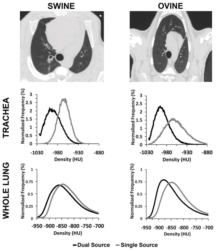
Swine and ovine were included to determine if thorax shape had an effect on the quantitative measurements in our scans. As seen in the top row of Figure 1, ovine have a more conical and deep dorsal to ventral dimensioned thorax, while swine have a more ovoid and human-like thorax.
Figure 1.
Swine (top-left panel) have a more vertically dimensioned thorax compared to the more human-like thorax present in ovine (top-right panel). A positive HU shift is present in the histograms of both the trachea (32–35HU, middle row) and whole lung regions (10–12HU, bottom row) between SS and DSDE modes. The normalized density histograms shown are derived from 140 kVp scans from example animals.
Animals were scanned in the SS mode (80, 100, 140 kVp), and in the DSDE mode (80/140Sn kVp, 140/80 kVp, and 100/140Sn kVp) while exploring the effect, if any, of varying available scanning parameters. Such parameters included rotation time (0.28, 0.33, or 0.5s); pitch (0.45, 0.55, or 1.0); slice thickness (0.6 or 0.75mm); scan direction (cranio-caudal or caudo-cranial); detector collimation (64 or 128); and reconstruction kernel (B35f or D30f). A consistent CTDIvol of 12 (+/− 0.1)mGy was used for all scans, except the dose controlled scans which had a CTDIvol of 6 (+/− 0.1)mGy.
Analysis
Semi-automated airway and whole lung segmentations of the animal scans were performed using the Pulmonary Analysis Software Suite (PASS) 29. To ensure that only lung tissue or tracheal air was used in voxel densitometry calculations, resultant segmentations from PASS were spherically eroded by 3 voxels in the trachea, and 10 voxels in the whole lung to minimize contamination by the chest wall, mediastinum or tracheal wall. Airway segmentation was then limited to only include the tracheal lumen between the end of the distal endotracheal tube and the carina. To avoid the early right bronchus take-off in these animals, the endotracheal tube was situated just distal to the vocal folds. Additional manual segmentations were taken of the inferior vena cava (IVC) between the diaphragm and the base of the heart, being careful to avoid any partial volume effect from the lung and keeping distance from the heart to avoid any motion artifact. The tracheal, IVC, and lung parenchymal regions of interest (ROIs) were compared for each of two scanning modes (SS & DSDE). Unlike the phantom studies, in the animal studies we did not do the DSDE-SS because this mode was not available at the time of scanning.
Phantom Protocol
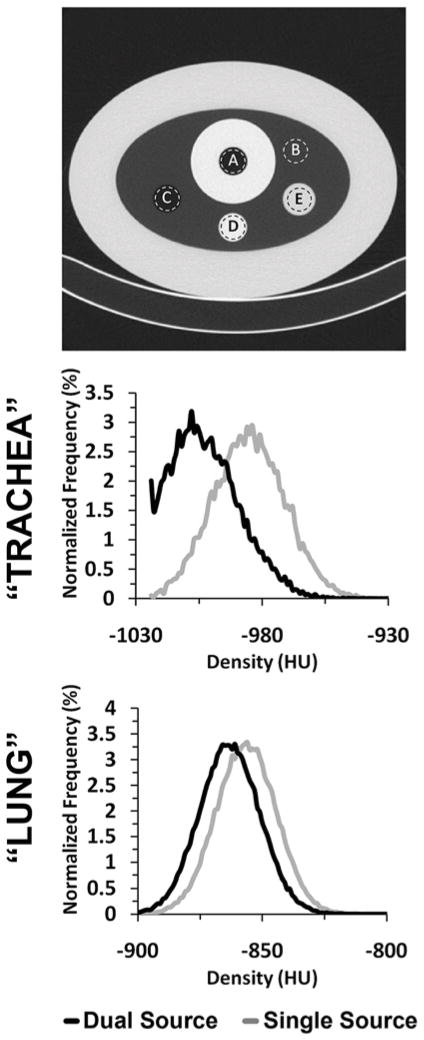
We used a variant of the COPDGene Phantom 30 (Phantom Laboratories, Salem, NY) (Fig. 2, upper panel). This phantom consists of an outer ring that has the x-ray attenuation characteristics similar to water (7–20HU). The inside of the ring contains a foam material (sampled in region B of Fig. 2) with an average CT attenuation close to that of lung parenchyma (~−860HU). There are three inserts within the foam material in the phantom: a 3.2 cm polymer bottle filled with distilled water (E in Fig. 2), a 3 cm air hole (C in Fig. 2) and a 3 cm acrylic rod (D in Fig 2). In addition to the air within region C, a second air region (A in Fig. 2) is surrounded by an acrylic ring simulating attenuation of the mediastinum and tracheal wall to better represent potential tracheal air artifacts.
Figure 2.
A variant of the COPDGene phantom (top panel), with regions representative of the trachea (A), lung parenchyma (B), air (C), acrylic (D), and water (E), was scanned in SS, DSDE and DSDE-SS modes at 80, 100 and 140 kVp. A HU shift between SS and DSDE modes is demonstrated in the histograms of both the “tracheal” (26HU, middle panel) and the “lung” regions (10HU, lower panel). The normalized density histograms shown are derived from SS and DSDE 140 kVp scans. Similar shifts are also seen in the 80 and 100 kVp scans.
The phantom was scanned in the SS mode (80, 100, 120 and 140 kVp), in the DSDE mode (80/140Sn kVp, 140/80 kVp, and 100/140Sn kVp), and in the DSDE-SS mode (the same combinations as in the DSDE mode but with tube A or B set at min mAs). A consistent CTDIvol of 12 (+/− 0.1)mGy was used for all scans, except the dose controlled scans which had a CTDIvol of 6 (+/− 0.1)mGy. Additional controlled scans were acquired comparing: rotation time (0.33 or 0.5s); pitch (0.55 or 1.0s); slice thickness (0.6 or 0.75mm); slice spacing (0.5 or 0.6mm); scan direction (cranio-caudal or caudo-cranial); number of detectors used (64 or 128); and reconstruction kernel (B35f or D30f).
Analysis
The phantom inserts were manually segmented across the central third of the z-axis extent for each of the five distinct regions of interest (actual ROIs are approximated by the illustrative dashed lines: A, B, C, D, E shown in the upper panel of Fig. 2), being careful to avoid any partial volume effect from the wall regions. The same ROI placements were used for each scan (SS, DSDE or DSDE-SS) acquired in the phantom experiment. Voxel densitometry measures of mean, median, mode, and standard deviation were then recorded along with histogram results.
Two-tailed paired difference t-tests were performed on both phantom and animal models by taking the mean density values within segmented regions of a SS scan and comparing it to the corresponding region on a DSDE or DSDE-SS scan. A Bland-Altman plot of the mean of SS & DSDE vs. the difference between them was constructed for both the phantom and animal models in the lung parenchyma and trachea regions. These plots were constructed using the mean difference on a slice-by-slice basis in both 80 and 140 kVp scans along the transverse axis of the segmented region of interest. An axial profile plot was constructed to show the relationship between the mean lung densities and the difference within individual transverse lung section along the z-axis.
Results
Animal Study
The animal study demonstrated that, within the lung and tracheal regions of both ovine and swine, the mean and median of the density histograms are close to −1000HU when running the scanner in the DSDE mode (Fig. 1), while the mean and median are shifted significantly (p < 0.001) towards more positive HU values (representing increased attenuation) by 32HU on average when using the scanner in the SS mode (Table 1). This behavior (shown in Fig. 1, middle and lower panels for 140 kVp) was observed for all three kVp values of tube A (80, 100 and 140) used in the DSDE vs. SS comparison. There is a statistically significant (p < 0.001) quantitative shift in CT numbers seen in the IVC when comparing SS and DSDE modes. Unlike in the less dense, more air-like, regions of thorax – where DSDE mode measures are more negative – the HU shifting within the more dense (relative to lung parenchyma) IVC blood is in the positive direction (Table 1).
Table 1.
Six ovine and 13 swine were scanned in SS and DSDE mode, with lungs inflated at 5, 15, 20, or 25 cm H2O airway pressure; the tracheal lumen, inferior vena cava, and lung parenchyma were segmented for determination of the respective mean HU and standard deviations. Two-tailed paired-difference t-tests were used to determine the p-values for the SS vs. DSDE comparisons across subjects. Shown are the HU values from the animal models from 80 kVp scans, with all scanning parameters matched except for scanning mode. A significant shift in HU is seen when comparing the trachea, IVC and lung tissue in the paired SS vs. DSDE scans for both swine and ovine.
| Swine | Ovine | ||||
|---|---|---|---|---|---|
| SS | DSDE | SS | DSDE | ||
| Trachea | Mean | −949 | −981 | −954 | −986 |
| Difference ± SD | 32 ± 6 | 32 ± 7 | |||
| T-Test | p < 0.001 (n = 18) | p < 0.001 (n = 12) | |||
|
| |||||
| Lung | Mean | −709 | −733 | −773 | −794 |
| Difference ± SD | 24 ± 15 | 19 ± 5 | |||
| T-Test | p < 0.001 (n=18) | p < 0.001 (n=12) | |||
|
| |||||
| IVC | Mean | 24 | 39 | 23 | 37 |
| Difference ± SD | −15 ± 1.6 | −14 ± 1.5 | |||
| T-Test | p < 0.001 (n = 18) | p < 0.001 (n = 12) | |||
In the DSDE mode, the normalized density histograms derived from the images reconstructed with the B35f and D30f kernels were nearly identical. This is expected. As discussed above, the physical characteristics of both kernels are similar. No other acquisition/reconstruction parameters showed an effect on the mean and median values of the density histograms.
A plot of the SS vs. DSDE air values sampled from a representative ovine trachea (Fig. 3A, left panel) demonstrates a relatively uniform attenuation throughout the trachea in the DSDE scans with considerable variability in air values sampled from the SS scans. A Bland-Altman plot from the same ovine trachea (Fig. 3A, right panel) demonstrates a mean biased slope of 1.84, with the mean difference being 18.70HU between the SS and DSDE scan. The lung parenchyma (Fig. 3B, left panel) shows a good correlation between the SS and DSDE scans. However, the Bland-Altman plot (Fig. 3B, right panel) shows a bias in the opposite direction to the trachea with a slope of −0.0871 and a mean difference of 6.25HU. The Bland-Altman plot could be seen as a series of upward sloping relationships that mimic the tracheal relationship, possibly representing varying slice-to-slice dominance of larger vs. smaller bronchial segments. While details are slightly different between ovine and swine data sets, all animals showed similar relationships as demonstrated in Figure 3A and 3B. To demonstrate the local effects of thoracic structures on scatter, in Figure 4 we provide plots of lung density vs. base-to-apex distance along the lung plotted against the difference between the DSDE and SS scans. The mean lung density represents the mean of the DSDE and SS slice means. Axial profile plots (Fig. 4A and Fig 4B, left panels) demonstrate the relationship between the mean slice densities in the tracheal air and parenchymal regions imaged using the SS and DSDE scan modes for an example swine (A) and and ovine (B). The relationship between structure shown as anterior-posterior and lateral volume renderings and scatter correction effects are highlighted by the shaded areas color coded similarly in the right and left panels. Note that the DSDE vs. SS differences are greatest in the apical regions of the thorax where scapular, sternal and spinal structures converge to cause the greatest amount of scatter, accounted for by the scatter corrections inherent to the DSDE imaging. Increased noise in the tracheal region of the swine data set vs. the ovine data set was likely due to the fact that there was an endotracheal tube in a portion of the swine tracheal region but not the ovine tracheal region. In both cases, SS and DSDE-based HU shifts observed in the trachea are also observe in the lung parenchyma.
Figure 3.
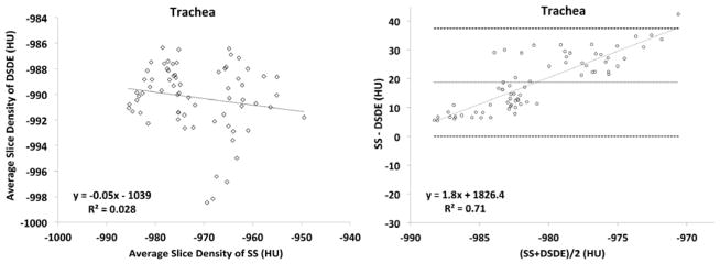
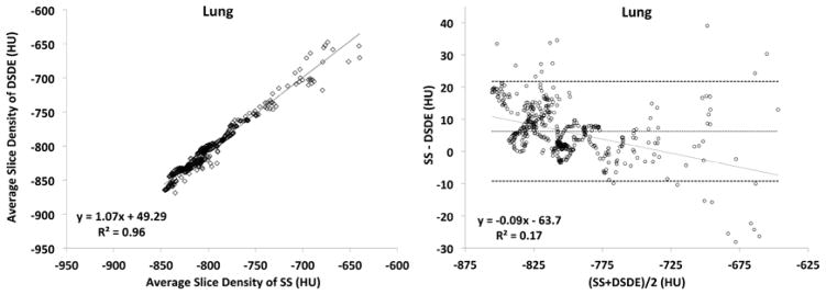
A&B. Linear regression plots of average slice densities comparing SS and DSDE at 80 kVp are shown for the in-vivo trachea (3A, left-panel) and lung parenchyma (3B, left panel) from an example swine. Similarly, Bland-Altman plots show the relationship of the mean of the average slice densities from the SS and DSDE scans vs. the difference between values obtained from the two scanning modes operated at 80 kVp. Data obtained from the trachea (3A, right-panel) and lung parenchyma (3B, right-panel) of the same swine as depicted in the left panels.
Figure 4.
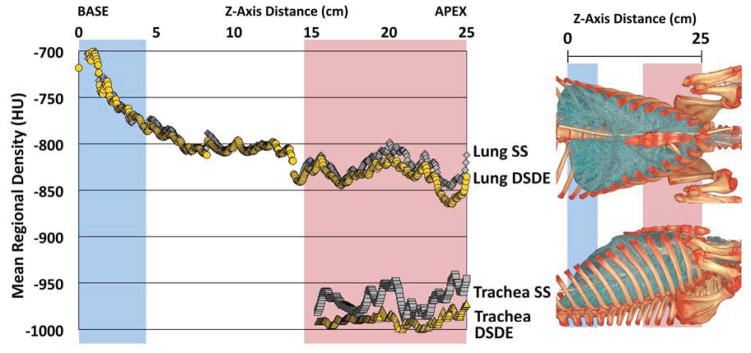
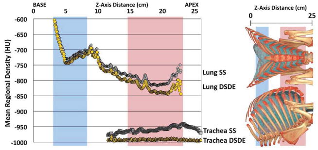
A&B. Mean of tracheal and lung HU values along the z-axis from SS and DSDE (80 kVp) scans SS data are in grey and DSDE are in yellow. for an example swine (A) and ovine (B). Anatomical reference volume rendered images (right panel) in the dorsal-ventral and lateral projections of the swine (A) and ovine (B) are provided to demonstrate the anatomic basis for the SS-DSDE differences. Color coded background bars are provided to help link the anatomic locations to the positions on the density graphs. Note that SS vs. DSDE difference in the trachea are reflected in the lung and the greatest SS vs. DSDE differences in both the lung and tracheal regions occur in an anatomic location associated with the sternum and scapula regions.
Phantom Study
Similar to the animal experiment, a statistically significant (~16HU, p < 0.001) shift between the mean HU values derived from the SS and DSDE modes (Fig. 2) was observed in the “tracheal” region of the phantom (Fig. 2, region A), with the DSDE scans producing CT numbers closer to the nominal air value of −1000HU. This shift was essentially the same when using either the DSDE or DSDE-SS modes (which showed a correlation of p < 0.05 with each other) and was similar for all kVp values.
The phantom inserts representing different materials demonstrated the HU shifts of varying magnitudes, directions and significances (Table 2). For example, in the region simulating the trachea, the difference is significant at over 15HU, with the DSDE scan resulting in a more negative HU value. Meanwhile, in the acrylic region, the difference between the two scan modes was over 20HU when comparing 140 kVp values, with the DSDE scan resulting in a more positive HU value.
Table 2.
A variant of the COPDGene phantom (Fig. 2, top panel), with “trachea” and “lung” like regions as well as air, water, and acrylic regions, was scanned in SS and modes at 80, 100 and 140 kVp. The resultant mean values of the 80 and 140 kVp scans are listed for each region, in addition to the difference in values between the two modes and the level of significance using a two-tailed paired difference test. The results from the 100 kVp showed similar HU shifts between SS and DSDE scans.
| 80 kVp | 140 kVp | ||||
|---|---|---|---|---|---|
| SS | DSDE | SS | DSDE | ||
| “Trachea” | Mean | −987 | −1003 | −987 | −1004 |
| |Difference| ± SD | 16 ± 2 | 17 ± 2 | |||
| T-Test | p < 0.001 (n = 10) | p < 0.001 (n = 10) | |||
|
| |||||
| Air | Mean | −999 | −1002 | −998 | −1004 |
| |Difference| ± SD | 3 ± 4 | 6 ± 2 | |||
| T-Test | p < 0.05 (n = 10) | P < 0.001 (n = 10) | |||
|
| |||||
| “Lung” | Mean | −858 | −860 | −856 | −863 |
| |Difference| ± SD | 2 ± 5 | 7 ± 3 | |||
| T-Test | p = 0.1701 (n = 10) | p < 0.001 (n = 10) | |||
|
| |||||
| Water | Mean | −2 | 2 | −2 | 2 |
| |Difference| ± SD | 4 ± 8 | 4 ± 6 | |||
| T-Test | p = 0.1816 (n = 10) | p = 0.0972 (n = 10) | |||
|
| |||||
| Acrylic | Mean | 94 | 111 | 125 | 154 |
| |Difference| ± SD | 17 ± 15 | 29 ± 8 | |||
| T-Test | p < 0.01 (n = 10) | p < 0.001 (n = 10) | |||
Note: Reference CT number for internal “trachea” air is −1000 HU; internal air is −1000 HU; “lung” is −860 HU; water is 0 HU; acrylic is 120 HU.
The observed DSDE vs. SS behavior remained similar across all acquisition/reconstruction parameters used in the experiment, though some of the parameter changes were blunted (Table 3). Standard deviation (image noise) in the DSDE mode was consistently higher than in the SS or DSDE-SS modes. This is expected because matching CTDIvol between the DSDE and SS modes resulted in much lower dose per tube for the DSDE mode because the CTDIvol is split between the two tubes.
Table 3.
The “trachea” like region of a variant of the COPDGene phantom was scanned in SS mode (80, 100, 120 and 140 kVp), in the DSDE mode (80/140Sn kVp, 140/80 kVp, and 100/140Sn kVp), and in the DSDE-SS mode (the same combinations as in the DSDE mode but with tube A or B set at min mAs). A consistent CTDIvol of 12 (+/− 0.1) mGy was used for each. The results here show the mean HU for a sampling of the analyzed parameter changes. Additional controlled scans comparing slice thickness (0.6 or 0.75mm), slice spacing (0.5 or 0.6mm), and scan direction (cranio-caudal or caudo-cranial) were also analyzed but not shown to have any meaningful difference in mean values compared to the control.
|
Phantom “Trachea” values
| ||||||||
|---|---|---|---|---|---|---|---|---|
| Scan Mode | Mean | Channels | Pitch | Rot. Time | Kernel | Tube | Sn filtered | |
| 80 kVp | SS | −987 | 128 | 0.55 | 0.5 | B35f | A | - |
| DSDE-SS | −1002 | 64 | 0.55 | 0.5 | B35f | A | - | |
| DSDE-SS | −1002 | 128 | 0.55 | 0.5 | B35f | A | - | |
| DSDE | −1002 | 128 | 0.55 | 0.5 | B35f | A | - | |
| DSDE | −1002 | 128 | 1.0 | 0.5 | B35f | A | - | |
| DSDE | −1001 | 128 | 0.55 | 0.33 | B35f | A | - | |
| DSDE | −1003 | 128 | 0.55 | 0.5 | D30f | A | - | |
| DSDE-SS | −1003 | 64 | 0.55 | 0.5 | B35f | B | - | |
| DSDE-SS | −1004 | 128 | 0.55 | 0.5 | B35f | B | - | |
| DSDE | −1003 | 128 | 0.55 | 0.5 | B35f | B | - | |
| DSDE | −1002 | 128 | 1.0 | 0.5 | B35f | B | - | |
| DSDE | −1003 | 128 | 0.55 | 0.33 | B35f | B | - | |
| DSDE | −1002 | 128 | 0.55 | 0.5 | D30f | B | - | |
|
| ||||||||
| 100 kVp | SS | −988 | 128 | 0.55 | 0.5 | B35f | A | - |
| DSDE-SS | −1004 | 64 | 0.55 | 0.5 | B35f | A | - | |
| DSDE-SS | −1007 | 128 | 0.55 | 0.5 | B35f | A | - | |
| DSDE | −1002 | 128 | 0.55 | 0.5 | B35f | A | - | |
|
| ||||||||
| 120 kVp | SS | −985 | 128 | 0.55 | 0.5 | B35f | A | - |
|
| ||||||||
| 140 kVp | SS | −987 | 128 | 0.55 | 0.5 | B35f | A | - |
| DSDE-SS | −1002 | 64 | 0.55 | 0.5 | B35f | A | - | |
| DSDE-SS | −1007 | 128 | 0.55 | 0.5 | B35f | A | - | |
| DSDE | −1002 | 128 | 0.55 | 0.5 | B35f | A | - | |
| DSDE-SS | −1000 | 64 | 0.55 | 0.5 | B35f | B | yes | |
| DSDE-SS | −1001 | 128 | 0.55 | 0.5 | B35f | B | yes | |
| DSDE | −1003 | 128 | 0.55 | 0.5 | B35f | B | yes | |
Note: Reference CT number for internal “trachea” air is −1000 HU.
Plots obtained from the phantom (Fig. 5A and 5B) are shown in formats similar to the in vivo plots represented in Figure 3. While the trends between the phantom and animal studies are similar, the phantom is missing the sloping relationship seen in the Bland-Altman plots because of the missing added scatter effects associated with anatomic structure. Bland-Altman plots in the phantom “trachea” segment (Fig. 5A, right panel) show a steady difference of mean slice values, with the mean difference being 13.89HU between the SS and DS scan. Similarly, the “lung” segment (Fig. 5B, right panel) shows a consistent difference of 3.85HU.
Figure 5.
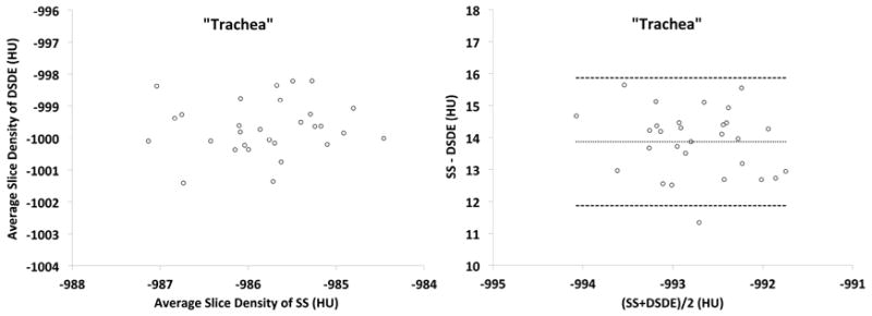
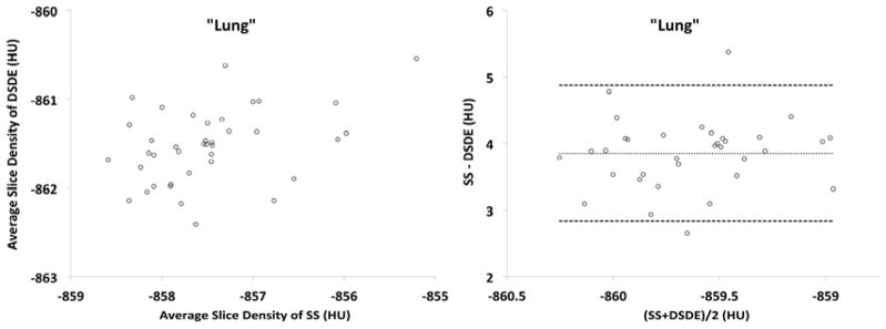
A&B. These plots are similar to those shown in Figure 3 but are derived from a variant of the COPDGene Phantom.
Discussion
Our animal and phantom studies demonstrated that the Definition Flash scanner provided more accurate CT numbers of air within the in-vivo trachea and within the trachea-like portion of the phantom when the scanner was operated in the DSDE mode. A significant positive shift of 15–35HU in the animal and phantom experiments was consistently observed when the scanner was operated in the SS mode representing scanning similar to that used in a conventional single-source CT. An overall smaller (but significant) shift on the order of 10HU was observed for the whole-lung histograms; these shifts are markedly more apparent in anatomically dense, and complex regions, e.g. the apical lung regions.
Even though there are many different confounding factors that potentially shift CT-derived air values from the nominal value of −1000HU, the two most likely causes are scatter and beam hardening. To the best of our knowledge, the beam hardening correction is the same for both SS and DSDE modes of operation. On the other hand, the anti-scatter solutions are very different between the two modes. The SS mode relies on the grid of anti-scatter collimators located at the detector level to block all scattered radiation and, hence, no specific scatter correction method is used. On the contrary, the DSDE mode relies on the correction method based on real-time measurements of scattered radiation. Therefore, the results of this study suggest that the dedicated scatter correction technique employed by the Definition Flash. 28 in the DSDE mode plays a major role in generating more accurate CT numbers for tracheal air which are closer to the nominal value of −1000HU.
Dual-source CT (DSCT) requires a very different approach for scatter correction compared to conventional single-source CT. With both tubes operating simultaneously, scattered photons originating from tube A can be detected not only by detector A (i.e., forward scatter as in conventional CT) but also by detector B and vice versa resulting in cross-scattered radiation. Compensation for cross- scattered radiation were reported for the first generation DSCT 32 and modified for the second generation DSCT 28. The later scatter correction method employs on-line measurements of both cross-scattered and forward-scattered radiation during a DSCT scan. When the full beam collimation (128×0.6 mm) is used, these measurements are done using the dedicated sensors located outside the cone beam in the z direction. When a partial beam collimation (e.g., 64×0.6 mm) is used, these measurements are done using the outer detector rows outside of the collimated beam.
More accurate CT numbers of air produced by the DSDE mode can be attributed to a better compensation of forward-scattered radiation by use of added scattered radiation sensors, placed on both sides of the primary detector module compared to the SS mode that only relies on the anti-scatter collimators placed above the primary detector pixel elements 28. These added scatter radiation sensors in DSDE mode result in additional compensation for forward-scattered radiation which is not completely blocked by the anti-scatter collimators. 28. The phantom scans done in the DSDE-SS mode provide evidence in support of this statement because both the SS and DSDE-SS modes were predominantly affected by forward-scattered radiation.. Moreover, no difference between the phantom results obtained in the DSDE and DSDE-SS modes indicates that the cross-scatter contribution is properly compensated and does not have a detrimental effect on the accuracy of air CT numbers.
Improving the accuracy of air CT numbers in the trachea and the lung parenchyma is of great importance for quantitative CT (QCT) lung imaging. Since all QCT lung measures (e.g., percentage of emphysema and air trapping) are based on the absolute HU thresholds (e.g., −950HU for emphysema), shifts in air CT numbers on the order of 20–35HU (as observed in this study) can result in significantly shifted estimates of percent emphysema scores. This is especially important for longitudinal and multi-center studies that involve scanners of different makes and models as well as scanner changes between time points. Because our results suggest that scatter correction serves to correct air values within both the in vivo lung scans as well as the phantom (more so in the in vivo scans) we conjecture that non-ideal compensation of forward-scattered radiation is likely a major factor responsible for the deviation of air CT numbers from the nominal value of −1000HU. Therefore, we believe that lung QCT can benefit from forward-scatter correction 33–35. Furthermore, the upward sloping tracheal Bland-Altman plots (Fig. 3A) along with the variable scatter effects on apical lung parenchyma (Fig. 5A and 5B) suggest that efforts to retrospectively correct lung attenuation based upon tracheal samples may be ill-advised.
In this study we only focused on the effect of scatter correction and did not investigate the effect of beam hardening which, for example, is well known to cause significant changes in CT numbers of iodine 36. Such investigation would involve scanning phantoms in a wide size range, while the phantom we used in this study was available only in one size. Nevertheless, no significant difference in the air CT numbers obtained at different tube energies ranging from 80 to 140 kVp (except a small ~3–6HU shift at 140Sn kVp) suggest that beam hardening is probably of less importance compared to scatter, at least under conditions of our experiments. Furthermore, because the same beam hardening correction algorithm is used in both DS and SS modes, we felt that the data presented provides the strongest evidence for scatter being the likely source of air value offset in the SS scanning mode.
In conclusion, our study suggests that the dedicated scatter correction technique employed by the DSDE mode of a second generation DSCT scanner results in more accurate CT numbers of the tracheal air compared to the SS mode representing conventional single-source CT.
Acknowledgments
Grants: This study was supported, in part, by the NIH RO1-HL-064368.
Footnotes
Conflict of interest: E.A. Hoffman is a founder and shareholder of VIDA Diagnostics, a company commercializing software, in part, developed at the University of Iowa. Andrew Primak is an employee of Siemens Medical Solutions, the company manufacturing the scanner used in this study.
Publisher's Disclaimer: This is a PDF file of an unedited manuscript that has been accepted for publication. As a service to our customers we are providing this early version of the manuscript. The manuscript will undergo copyediting, typesetting, and review of the resulting proof before it is published in its final citable form. Please note that during the production process errors may be discovered which could affect the content, and all legal disclaimers that apply to the journal pertain.
References
- 1.Matsuoka S, Yamashiro T, Washko GR, et al. Quantitative CT Assessment of Chronic Obstructive Pulmonary Disease1. Radiographics. 2010 Jan 1;30(1):55–66. doi: 10.1148/rg.301095110. [DOI] [PubMed] [Google Scholar]
- 2.Lynch DA. Quantitative CT of fibrotic interstitial lung disease. Chest. 2007 Mar;131(3):643–644. doi: 10.1378/chest.06-2955. [DOI] [PubMed] [Google Scholar]
- 3.Park EA, Goo JM, Park SJ, et al. Chronic obstructive pulmonary disease: quantitative and visual ventilation pattern analysis at xenon ventilation CT performed by using a dual-energy technique. Radiology. 2010 Sep;256(3):985–997. doi: 10.1148/radiol.10091502. [DOI] [PubMed] [Google Scholar]
- 4.Lynch DA, Newell JD. Quantitative imaging of COPD. J Thorac Imaging. 2009 Aug;24(3):189–194. doi: 10.1097/RTI.0b013e3181b31cf0. [DOI] [PubMed] [Google Scholar]
- 5.Aberle DR, Berg CD, et al. Team NLSTR. The National Lung Screening Trial: overview and study design. Radiology. 2011 Feb;258(1):243–253. doi: 10.1148/radiol.10091808. [DOI] [PMC free article] [PubMed] [Google Scholar]
- 6.Kim WJ, Hoffman EA, Reilly J, et al. Association of COPD candidate genes with computed tomography emphysema and airway phenotypes in severe COPD. The European respiratory journal: official journal of the European Society for Clinical Respiratory Physiology. 2011 Feb;37(1):39–43. doi: 10.1183/09031936.00173009. [DOI] [PMC free article] [PubMed] [Google Scholar]
- 7.Washko GR, Lynch DA, Matsuoka S, et al. Identification of early interstitial lung disease in smokers from the COPDGene Study. Acad Radiol. 2010 Jan;17(1):48–53. doi: 10.1016/j.acra.2009.07.016. [DOI] [PMC free article] [PubMed] [Google Scholar]
- 8.Bakker ME, Stolk J, Putter H, et al. Variability in densitometric assessment of pulmonary emphysema with computed tomography. Invest Radiol. 2005 Dec;40(12):777–783. doi: 10.1097/01.rli.0000186418.31139.21. [DOI] [PubMed] [Google Scholar]
- 9.Bankier AA, De Maertelaer V, Keyzer C, et al. Pulmonary emphysema: subjective visual grading versus objective quantification with macroscopic morphometry and thin-section CT densitometry. Radiology. 1999 Jun;211(3):851–858. doi: 10.1148/radiology.211.3.r99jn05851. [DOI] [PubMed] [Google Scholar]
- 10.Gurney JW, Jones KK, Robbins RA, et al. Regional distribution of emphysema: correlation of high-resolution CT with pulmonary function tests in unselected smokers. Radiology. 1992 May;183(2):457–463. doi: 10.1148/radiology.183.2.1561350. [DOI] [PubMed] [Google Scholar]
- 11.Lucidarme O, Coche E, Cluzel P, et al. Expiratory CT scans for chronic airway disease: correlation with pulmonary function test results. AJR Am J Roentgenol. 1998 Feb;170(2):301–307. doi: 10.2214/ajr.170.2.9456933. [DOI] [PubMed] [Google Scholar]
- 12.Knudson RJ, Standen JR, Kaltenborn WT, et al. Expiratory computed tomography for assessment of suspected pulmonary emphysema. Chest. 1991 Jun;99(6):1357–1366. doi: 10.1378/chest.99.6.1357. [DOI] [PubMed] [Google Scholar]
- 13.Brown M, Abtin F, Kim HJ, et al. Imaging biomarkers for patient selection and treatment planning in emphysema. Imaging in Medicine. 2010 Oct;2(5):565–573. [Google Scholar]
- 14.Buckler AJ, Mozley PD, Schwartz L, et al. Volumetric CT in lung cancer: an example for the qualification of imaging as a biomarker. 2010 Feb; doi: 10.1016/j.acra.2009.06.019. [DOI] [PubMed] [Google Scholar]
- 15.Bafadhel M, Umar I, Gupta S, et al. The Role of CT Scanning in Multidimensional Phenotyping of COPD. Chest. 2011 Sep 05;140(3):634–642. doi: 10.1378/chest.10-3007. [DOI] [PMC free article] [PubMed] [Google Scholar]
- 16.Goldin JG. Imaging the lungs in patients with pulmonary emphysema. J Thorac Imaging. 2009 Aug;24(3):163–170. doi: 10.1097/RTI.0b013e3181b41b53. [DOI] [PubMed] [Google Scholar]
- 17.Newell JD. Quantitative computed tomography of lung parenchyma in chronic obstructive pulmonary disease: an overview. Proceedings of the American Thoracic Society. 2008 Dec 15;5(9):915–918. doi: 10.1513/pats.200804-034QC. [DOI] [PubMed] [Google Scholar]
- 18.Coxson HO, Rogers Robert M. Quantitative computed tomography of chronic obstructive pulmonary disease. Academic Radiology. 2005 Nov;12(11):1457–1463. doi: 10.1016/j.acra.2005.08.013. [DOI] [PubMed] [Google Scholar]
- 19.Newell JD, Jr, Hogg JC, Snider GL. Report of a workshop: quantitative computed tomography scanning in longitudinal studies of emphysema. Eur Respir J. 2004 May;23(5):769–775. doi: 10.1183/09031936.04.00026504. [DOI] [PubMed] [Google Scholar]
- 20.Stolk J, Ng WH, Bakker ME, et al. Correlation between annual change in health status and computer tomography derived lung density in subjects with alpha1-antitrypsin deficiency. Thorax. 2003 Dec;58(12):1027–1030. doi: 10.1136/thorax.58.12.1027. [DOI] [PMC free article] [PubMed] [Google Scholar]
- 21.Coxson HO. Quantitative computed tomography assessment of airway wall dimensions: current status and potential applications for phenotyping chronic obstructive pulmonary disease. Proceedings of the American Thoracic Society. 2008 Dec 15;5(9):940–945. doi: 10.1513/pats.200806-057QC. [DOI] [PMC free article] [PubMed] [Google Scholar]
- 22.Hoffman EA, Simon BA, McLennan G. A structural and functional assessment of the lung via multidetector-row computed tomography: Phenotyping chronic obstructive pulmonary disease. Proceedings of the American Thoracic Society. 2006;3(6):519–534. doi: 10.1513/pats.200603-086MS. [DOI] [PMC free article] [PubMed] [Google Scholar]
- 23.Dirksen A, Piitulainen E, Parr DG, et al. Exploring the role of CT densitometry: a randomised study of augmentation therapy in alpha1-antitrypsin deficiency. The European respiratory journal: official journal of the European Society for Clinical Respiratory Physiology. 2009 Jul;33(6):1345–1353. doi: 10.1183/09031936.00159408. [DOI] [PubMed] [Google Scholar]
- 24.Flohr TG, Leng S, Yu L, et al. Dual-source spiral CT with pitch up to 3.2 and 75 ms temporal resolution: image reconstruction and assessment of image quality. Med Phys. 2009 Dec;36(12):5641–5653. doi: 10.1118/1.3259739. [DOI] [PubMed] [Google Scholar]
- 25.Johnson TRC, Krauss B, Sedlmair M, et al. Material differentiation by dual energy CT: initial experience. European Radiology. 2007 Jul;17(6):1510–1517. doi: 10.1007/s00330-006-0517-6. [DOI] [PubMed] [Google Scholar]
- 26.Yu L, Primak AN, Liu X, et al. Image quality optimization and evaluation of linearly mixed images in dual-source, dual-energy CT. Medical Physics. 2009;36(3):1019. doi: 10.1118/1.3077921. [DOI] [PMC free article] [PubMed] [Google Scholar]
- 27.Primak AN, Giraldo JCR, Eusemann CD, et al. Dual-Source Dual-Energy CT With Additional Tin Filtration: Dose and Image Quality Evaluation in Phantoms and In Vivo. American Journal of Roentgenology. 2010 Nov 01;195(5):1164–1174. doi: 10.2214/AJR.09.3956. [DOI] [PMC free article] [PubMed] [Google Scholar]
- 28.Petersilka M, Stierstorfer K, Bruder H, et al. Strategies for scatter correction in dual source CT. Med Phys. 2010 Nov;37(11):5971–5992. doi: 10.1118/1.3504606. [DOI] [PubMed] [Google Scholar]
- 29.Guo J, Fuld M, Alford SK, et al. Pulmonary Analysis Software Suite 9.0 Integrating quantitative measures of function with structural analyses. In: Brown M, de Bruijne M, van Ginneken B, Kiraly A, Kuhnigk JM, Lorenz C, Mori K, Reinhardt JM, editors. First International Workshop on Pulmonary Image Analysis. 2008. pp. 283–292. [Google Scholar]
- 30.Sieren JP, Gunderson K, Lynch DA, et al. COPDGene Phantom: Quality Control Of Quantitative Lung Imaging In A Multi-center Trial. Am J Respir Crit Care Med. 2010;181:A5519. [Google Scholar]
- 31.Miller RJ. Simultaneous Statistical Inference. New York: Springer Verlag; 1981. [Google Scholar]
- 32.Bruder H, Stierstorfer K, Petersilka M, et al. Correction of cross-scatter in next generation dual source. CT (DSCT) scanners. 2008;6913:69131W, 69131W–69110. [Google Scholar]
- 33.Ohnesorge B, Flohr T, Klingenbeck-Regn K. Efficient object scatter correction algorithm for third and fourth generation CT scanners. Eur Radiol. 1999;9(3):563–569. doi: 10.1007/s003300050710. [DOI] [PubMed] [Google Scholar]
- 34.Zhu L, Bennett NR, Fahrig R. Scatter correction method for X-ray CT using primary modulation: theory and preliminary results. IEEE Trans Med Imaging. 2006 Dec;25(12):1573–1587. doi: 10.1109/tmi.2006.884636. [DOI] [PubMed] [Google Scholar]
- 35.Siewerdsen JH, Daly MJ, Bakhtiar B, et al. A simple, direct method for x-ray scatter estimation and correction in digital radiography and cone-beam CT. Med Phys. 2006 Jan;33(1):187–197. doi: 10.1118/1.2148916. [DOI] [PubMed] [Google Scholar]
- 36.Schindera ST, Tock I, Marin D, et al. Effect of beam hardening on arterial enhancement in thoracoabdominal CT angiography with increasing patient size: an in vitro and in vivo study. Radiology. 2010 Aug;256(2):528–535. doi: 10.1148/radiol.10092086. [DOI] [PubMed] [Google Scholar]


