Abstract
Capsule endoscopy is a promising technique for diagnosing diseases in the digestive system. Here we design and characterize a miniature swimming mechanism that uses the magnetic fields of the MRI for both propulsion and wireless powering of the capsule. Our method uses both the static and the radio frequency (RF) magnetic fields inherently available in MRI to generate a propulsive force. Our study focuses on the evaluation of the propulsive force for different swimming tails and experimental estimation of the parameters that influence its magnitude. We have found that an approximately 20 mm long, 5 mm wide swimming tail is capable of producing 0.21 mN propulsive force in water when driven by a 20 Hz signal providing 0.85 mW power and the tail located within the homogeneous field of a 3 T MRI scanner. We also analyze the parallel operation of the swimming mechanism and the scanner imaging. We characterize the size of artifacts caused by the propulsion system. We show that while the magnetic micro swimmer is propelling the capsule endoscope, the operator can locate the capsule on the image of an interventional scene without being obscured by significant artifacts. Although this swimming method does not scale down favorably, the high magnetic field of the MRI allows self propulsion speed on the order of several millimeter per second and can propel an endoscopic capsule in the stomach.
Keywords: Capsule endoscopy, MRI, Propulsion, Microrobot, Magnetic actuator
1 Introduction
Microrobots are 10 μm to 1 mm scale robots that offer a great potential benefit in medical diagnosis and treatment. A miniature robot of 1 to 10 mm in size has many micro components and can be considered an integrated miniature device. A good example of such a system with robotic aspects is the endoscopic capsule to image the small intestine (Moglia et al. 2007). Such a microsystem can replace the catheters and endoscopes that are currently used in minimally invasive surgeries (Nelson et al. 2010).
In addition to gastroenterology, microrobots can be used for other medical interventions, such as neurosurgery (Kosa et al. 2008a, b), ophthalmology (Yesin et al. 2006) or fetal surgery (Berris and Shoham 2006).
Swimming microrobots rely on various actuating principles such as piezoelectric (Kosa et al. 2007), magnetic (Dreyfus et al. 2005, Yesin et al. 2006, Zhang et al. 2009), Ionic Conducting Polymer Film (ICPF) (Guo et al. 2006), or even miniaturized electrical motors (Menciassi et al. 2008). Further interesting swimming methods are harnessing bacteria to propel the microdevice (Behkam and Sitti 2008) or directing ferromagnetic microorganisms MC-1 as carriers of nano particles (Martel et al. 2009). Pouponneau et al. (Pouponneau et al. 2011 from the group Martel) also used the same method to steer TMMC (therapeutic magnetic microcarriers) in the liver under MR imaging.
Several studies use magnetic forces to propel microsystems. The operational principle of these actuators can be classified into three main types: 1) placing a permanent magnet in a rotating magnetic field, thus creating rotation of a propeller, 2) placing a permanent magnet into a magnetic field with a gradient, and 3) creating a propulsive force by creating an undulating motion in an elastic tail.
Honda (Honda et al. 1996) made a 21 mm-long helix with a 1 mm3 Samarium Cobalt (SmCo) magnet at its head and achieved a swimming velocity of 20 mm/s. Sendoh et al. (Sendoh et al. 2003) used the same principle, but the helix was wrapped around a capsule and the permanent magnet was at the center of the capsule. In addition to swimming, this capsule can crawl in the small intestine using a screw-like motion. Bell (Bell et al. 2007) applied the same principle as Honda in a smaller scale and manufactured nanohelices out of a rectangular strip (40 μm length, 3 μm diameter, 150 nm helix strip thickness) and attached them to a magnetic microbead. The microhelix swimmer was further characterized by Zhang (Zhang et al. 2009).
Yesin (Yesin et al. 2006) used external coils to drive a 1 mm long ellipsoid microrobot embedded with neodymium (NdFeB) powder with a constant gradient magnetic field while stabilized by an additional constant magnetic field. (Mathieu et al. 2006) used the gradient coil of an MRI system to propel 600 μm magnetized steel beads (carbon steel 1010/1020). (Yi et al. 2004) made a 3 mm-long elastic tail of ferromagnetic polymer and achieved a swimming velocity of 0.9 mm/s using a 11.5 mT magnetic field. (Dreyfus et al. 2005) showed that a linear chain of colloidal magnetic particles linked by DNA and attached to a red cell, stabilized and actuated by an external magnetic field, can create undulating motion and swim. The filament’s length was 24 μm and it achieved a propulsive velocity of 3.9 μm/s. (Guo et al. 2008) made an elastic tail driven at its head section by a permanent magnet. The swimming velocity of the robot was 40 mm/s. (Liu et al. 2010) developed a 40 mm elastic tail made of a giant magnetostrictive thin film bimorph. The microdevice achieved a speed of 4.67 mm/s in gasoline (ν=0.29·10−3 μ/Pas) using a magnetic field of 21.5 mT.
All the actuators of the microdevices mentioned above use magnetic materials. Such materials create large artifacts in MR imaging and should not be used in the body during the imaging process (Mathieu et al. 2003).
Here we propose the use of a miniature swimming mechanism relying on the magnetic fields of the MRI for propulsion. Our method uses both the static and the radio frequency (RF) magnetic fields (B0 and B1) inherently available in an MRI scanner to generate propulsion force. The device includes three tails with two coils in each tail. A non-magnetic battery or the RF magnetic field of the MRI is utilized for powering the capsule. In Kosa et al. Kosa et al. 2008a, b we calculated that a voltage of 1.6 V can be induced in an 5×5 mm 10 turn coil. At a power matching 42 Ω load, the supply current to the robot may exceeds 200 mA, which is sufficient to power the six coils of the capsule. When the electric current of a coil interacts with the static magnetic field of the MRI a force is generated perpendicular to both the direction of the static magnetic field and the direction of the current flow. That force will bend the tail. Repeatedly bending the tail with both coils a propulsional force is generated in the direction of the tail.
The MRI still can function and be used to localize the swimming robot in cross-sectional images. This localization ability will help the operator to maneuver the capsule toward the region of interest quickly and reduce the overall examination time.
Figure 1 is a conceptual drawing that illustrates the ability to integrate our propulsive method into an endoscopic capsule. Such setup provides 5 DoF control into two steering and three propulsion directions. It is a realistic representation of an endoscopic capsule that uses battery for power source (2 in Fig. 1), a micro camera manufactured by Medigus Ltd. (5 in Fig. 1) and additional miniature boards for command control and communication (7 in Fig. 1).
Fig. 1.
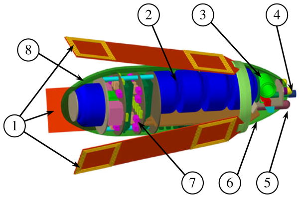
Illustration of an endoscopic capsule (size of φ12×32 mm spheroid) equipped with the magnetic propulsive system. The propulsive unit is made of 3 double coil magnetic swimming tails (1). The capsule payload is a micro-camera (5) and a tool for biopsy (4). The power source is made of 5 non-magnetic batteries (2). There is also electronics for command and control and communication (7), housing (8) and an antenna (3) for the RF transceiver. The housing is cut away to make the content of the capsule visible
A well suited application of this capsule is stomach and bowel inspection. In order to use the capsule the patient will drink proper amount of liquid prior to swallowing the biomedical device. At the end of the procedure the device will be disposed similarly to currently available endoscopic capsules.
Specifically, this paper reports on the swimming property of the microdevice in the MRI scanner having one or two coils and also evaluates the imaging artifact created by the electromagnetic copper coils. Earlier we published a theoretical analysis of the swimming method presented in this paper Kosa et al. 2008b and initial experimental results (Kosa et al. 2008b, Kosa 2010). In those earlier papers we used a tail having 3 coils and a model of traveling wave in an elastic beam in a low Reynolds number fluidic environment.
2 Theoretical background
The swimming microdevices we are characterizing in this study can be divided into two types. The first is an elastic polymer tail with one coil at its tip (see Fig. 2 left.) The second is a shorter tail with two coils in which the swimming is based on the phase difference in the actuation of the two rigid bodies (see Fig. 2 right.) The motion of the elastic tail is characterized by a continuous form that can be modeled by an Euler-Bernoulli bending beam (Kosa et al. 2008a, b). The tail’s swimming amplitude usually does not exceed L/10 (L is the length of the beam) distance from its center line; therefore there is no need to apply higher order elastic models (Lauga 2007, e.g.). The fluidic regime of the swimming is characterized by the Reynolds number (Re), which is defined as
Fig. 2.
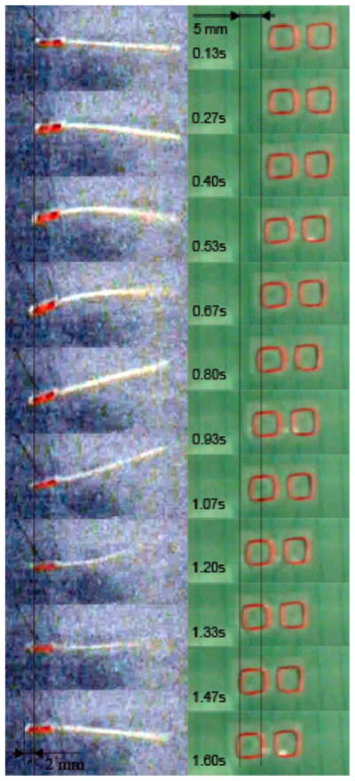
Illustration of the motion of an elastic tail with one coil at its head (left) and two coils (right)
| (1) |
ρ and μ are the density and absolute viscosity of water (ρ=1000 kg/m3 and μ=10−3 Pas). The characteristic length is based on the cross-section of the tails; we defined it as the width W=5.19 mm. The transverse velocity at the end of the tail is its characteristic velocity, 2πAf. A is the amplitude of the tail motion and f is the vibration frequency, where f=1.50 Hz and A=0.1 to 5 mm, resulting in a characteristic velocity of about 30 mm/s. The Re number is approximately:
| (2) |
From the motion images of the swimming actuators (Fig. 2, for example) we can see that the vibration of the tail is similar to a flexural standing wave and relatively small. Hence, we derive an Euler Bernoulli bending beam model to describe the natural frequencies of the magnetic swimmer.
The Euler-Bernoulli bending beam model, however, is too simple to accurately predict the swimming velocity and propulsive force. The elasticity and inertia of the Euler-Bernoulli model is accurate, but viscous damping cannot be used here because of the high Re numbers (2). We will therefore use this model only to estimate the natural frequencies of the elastic tail micro-devices.
2.1 Elastic beam swimming model
The first type of swimming will be described by an Euler-Bernoulli vibrating beam model. The experiments show that the amplitude of the beam’s vibration does not exceed a tenth of the length therefore this model approximation is valid (Meirovitch 1975).
Figure 3 Illustrates the characteristic variables and parameters of the tail. The field equation of the microdevice is (Meirovitch 1975)
Fig. 3.
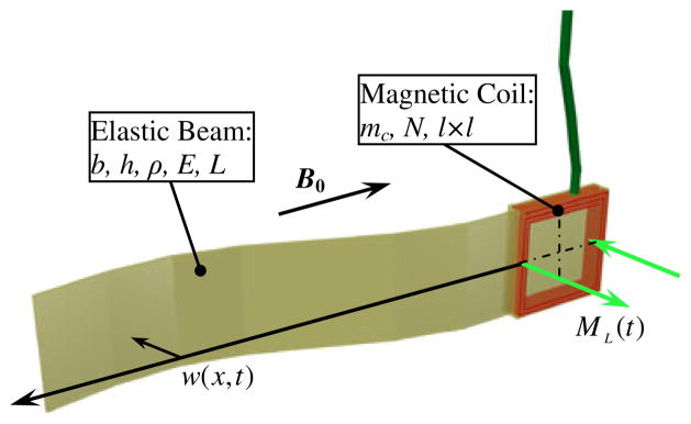
Schematic drawing of the single coil elastic beam microdevice
| (3) |
where w(x,t) is the lateral displacement of the beam at the location x at time t. The distributed mass of the beam is m=ρA, where A is its cross-section (in the case of a rectangular beam A=bh) and ρ its density. The added mass of the fluid that is moving with the beam is m̂ = ρWπb2/4, where ρw is the density of the liquid and b is the width of the beam. E is the Young modulus of the beam, and I (in the case of a rectangular cross-section I=bh3/12) is the cross-section inertia. The hydrodynamic force exerted by the fluid on the beam is q(x,t).
The boundary conditions of the beam are
| (4) |
where J is the inertia of the coil at the base of the tail,
| (5) |
and M is the mass of the coil:
| (6) |
The parameters of the coil are: N the number of turns, l the length and width (the coil is square) and mc the weight per unit length.
ML(t) is the torque applied by the Lorenz force on the microdevice:
| (7) |
B0 is the constant magnetic field of the MRI. Because of the small bending angle, , of the tail we assume that ML(t) is orthogonal to the tail. i(t) is the alternating current in the coil:
| (8) |
Using separation of variables:
| (9) |
Ci are constants, β is an independent variable defined by the boundary conditions and is the natural frequency of the device.
We derive the natural modes and frequencies of the systems by substituting the solution (9) into the field equation and (3) and boundary conditions (4) and separating the mode ϕ(βx) from the evolution function f(ωt). The result is the following transcendental equation with the variable β:
| (10) |
and the parameters of the equation are: γ1 = K/EI; γ2 = Kθ/EI; γ3 = J(m + m̂)/(EI)2; γ4 = M(m + m̂)/(EI)2;From the term (10), one can quite easily derive the equation of a free-free (unlimited on both sides) beam ( eq(10)):
| (11) |
or a cantilever ( eq(10))
| (12) |
which are the limit cases of the natural frequency variation.
2.2 Double coil swimming model
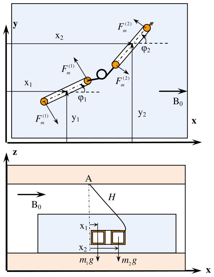
In contrast to a single coil swimmer, a double coil swimmer is formed by two rigid coils with a connecting elastic section that is relatively small. The motion of this swimmer can be simulated by rigid body dynamics as illustrated in Fig. 4. The model has 6° of freedom from which 4 are redundant and used to simplify the description of the system.
Fig. 4.
Illustration of the forward motion of a swimming tail with two coils. The model is shown in top (upper drawing) and side view (lower drawing.) The two drawings are not to the same scale and the individual turns in the coil are represented by a single loop
Each coil has a mass of M and inertia J=5/6NMl2. The angular spring sets the system’s stiffness and drag forces are applied in the normal and tangential direction of the coils.
The external force applied on the system is the Lorentz force created by the vector product of B0 and the current in the coil i(k)(t):
| (13) |
The torque on each coil is:
| (14) |
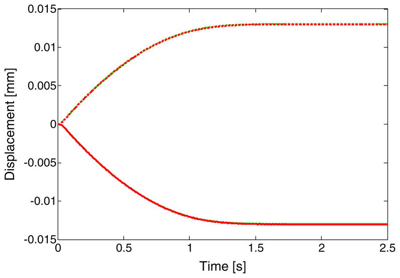
The system is solved by using the method developed by Ekeberg (Ekeberg 1993). Figures 5 and 6 illustrate the swimming of such a model. In Fig. 5 the swimming experiment is reconstructed by the theoretical model. We added a recoil force (See Fig. 4), defined by
Fig. 5.
x1 (red) and x2 (green) in time during forward (solid) and backward (dash dot) swimming. x1 and x2 values are adjacent thus it is difficult to distinguish between them
Fig. 6.
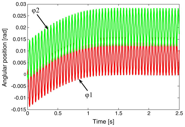
ϕ1 (red) and ϕ2 (green) in time. The steady state vibration response of the angles are between ϕ1=[0,0.016] and ϕ2=[0.012,0.028]
| (15) |
to simulate the force applied by the hanging wire on the tail. The term of the recoil force is derived from the torque equilibrium around the hanging point designated by A in Fig. 4. H is the length of the wire which is also approximately the hanging height of the microdevice. As in the experiment, the maximal deflection is at the current phase differences 90° and −90°. The operating frequency is 20 Hz and the tail’s length is 23 mm.
Figure 6 presents the simulation of the angles ϕ1 and ϕ2 (see Fig. 4) after the system is in a dynamic equilibrium with the recoil forces. At steady state swimming the angles converge.
3 Materials and methods
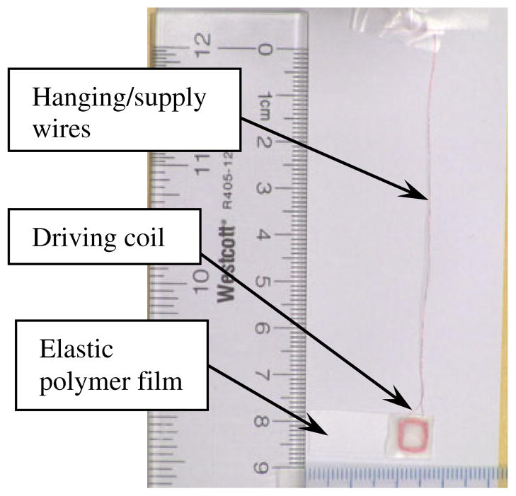
The elastic polymer tail, shown in Fig. 7, is built from Pop-up Scotch tape (Pop-up Tape, 3 M, St. Paul, MN 55144) and coils were made from 44 AWG round, single build MW79C magnet wire (MWS Wire Industries, Westlake Village, CA 91362).
Fig. 7.
Picture of an elastic polymer tail
It is necessary to have a good estimate of the physical properties of the components of the elastic polymer tail for the swimming model. While some of the tail’s physical properties were measured directly, others were estimated from measurements made on a larger piece. For example, while the resistance of the coils were measured directly, their weight and size were computed. Determining the elasticity of the polymer tape used a special setup.
The driving signal to all the coils was sinusoidal without a DC offset. We measured and quoted the peak to peak amplitude of the currents of the coils in mApp. The frequency of the signal was set in Hz.
MAGNETOM Verio 3 T, Siemens MRI scanner was used in all the swimming experiments.
3.1 Static bending
To measure the elasticity of the polymer tape, weights were made out of a 32 AWG round, single build magnet wire. The weight of a 3 meter-long wire was measured with an American Weight Scale (3285 Saturn Court Norcross, GA 30092) model BT2-201. It is 0.89 g. Based on this measurement, several 33 mm-long pieces were cut from a 32 AWG wire it, each supposedly weighing 0.01 g. Then, one end of the tape was fastened to a large metal block. Weights were placed onto the other end of the tape in 0.01 g increments. The bending was observed as shown in Fig. 8.
Fig. 8.
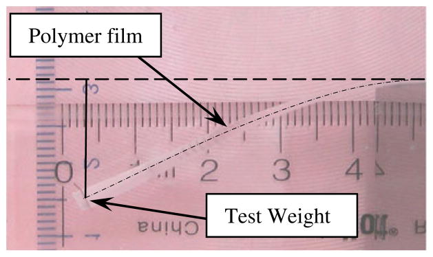
Illustration of setup of determining elasticity of the polymer tape. The dashed line is the height of the tail’s base and the vertical line shows the deflection of the end of the tail. The dash-dot curve emphasizes the center line of the film
From the deflection shown in Fig. 8 we can derive the stiffness of the tail, EI, and its distributed mass, m (see section 2.1 for further details) by integration of the bending equation:
| (16) |
Nw is the number of weights at the end of the tail, mw is the mass of each weight and g is gravity.
The theoretical deflection of the tail is:
| (17) |
We derive Young modulus of elasticity, E, and specific mass, ρ, by fitting the experimental deflection to (17). The results of the approximation are:
| (18) |
3.2 Elastic tail experimental setup
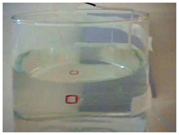
A cylindrical glass container having a diameter of 100 mm was partially filled with tap water. The container was located on the patient table in the homogeneous region of the MR. The tail was hung from above such that it was completely submerged in water (See Fig. 9). The coil terminals were connected to the output of a HP 33120A Function generator (Agilent Technologies, Inc. Santa Clara CA 95051).
Fig. 9.
Picture of an elastic polymer tail in a container filled with water and placed at the homogeneous region of the MRI
The amplitude and the frequency of the driving current were changed while the deviation from the resting position of the elastic tail was recorded on video.
3.3 Rigid tail experiment setup
A 235 mm by 185 mm by 70 mm slightly tapered glass container was partially filled with tap water. The tail was hung from above by the leads of the coils and the tail was submerged into the water in the container. The container was placed on the patient table and was advanced to the homogeneous region of the magnet. The coils were driven by the headphone output of a personal computer (DELL Inc. Inspiron Mini 9, One Dell Way Round Rock, Texas 78682). Adobe Audition software (Adobe Systems Inc. San Jose, CA 95110) was used to generate the waveforms. The waveforms consisted of sets of 5 s of signal of a needed frequency followed by 5 s of silence. The set included sinusoidal signals phase shifted by 0, 90, 180 and 270 ° between the left and right channels. The amplitude of the signals were changed by rescaling the waveforms.
4 Results
4.1 Swimming experiments
We characterized the motion of several swimming tails. The data from the experiments is summarized in Figs. 8, 9, 10, 11, 12, 13, 14, 15, 16, 17, 18, 19, 20. The characterizing parameters and identified resonances of each swimming tail are described in Tables 1 and 2. The prototypes of the elastic tails have been created to systematically investigate the influence of two main parameters (see Table 1):
Fig. 10.
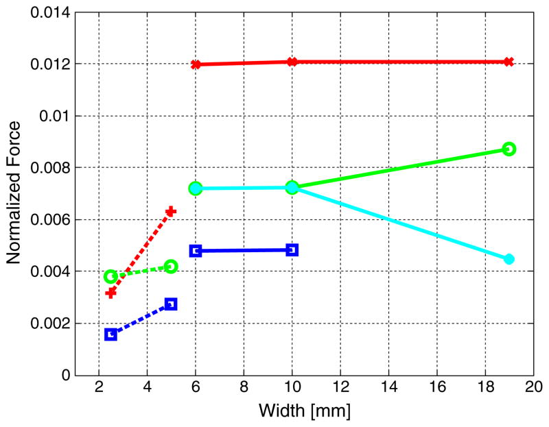
Comparison of the normalized propulsive force at different widths. Tails II, III and IV are compared at the input currents and frequencies: 2.39 mApp and 1 Hz (red line with cross marker); 4.96 mApp and 5 Hz (green line and hollow circle marker); 4.96 mApp and 20 Hz (blue line and square marker) and 7.19 mApp and 20 Hz (cyan line and full circle marker). Tails I and V are compared at the input current 25.31 mApp and the frequencies: 10 Hz (red dashed line with plus marker); 20 Hz (green dashed line with circle marker) and 45 Hz (blue dashed line with square marker)
Fig. 11.
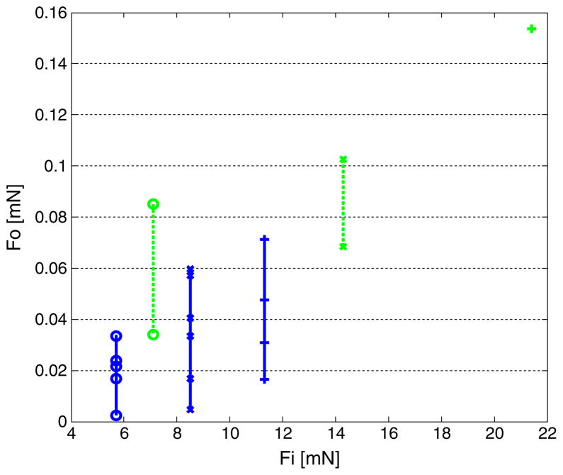
Comparison of the propulsive force at different input forces in tails I and II. The markers designate the peaks of the resonances at each input current. The input currents of tail I (blue solid line) and II (green dashed line) are: 12.65 mApp (circle), 18.98 mApp (cross), 25.31 mApp (plus) for I and 2.39 mApp (circle), 4.79 mApp (cross), 7.19 mApp (plus) for II
Fig. 12.
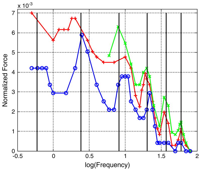
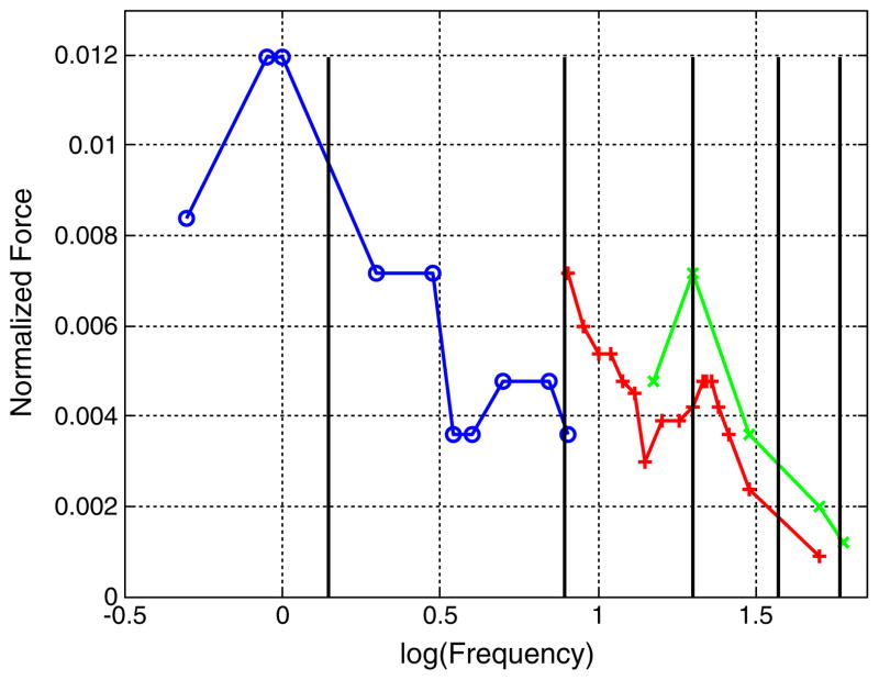
Swimming results for tail I: normalized force versus normalized frequency as a parameter of the driving current. Each cross mark represents a data point from the experiment. The coil driving currents were: 12.65 mApp (blue circle), 18.98 mApp (red plus) and 25.31mApp (green cross). The vertical solid black lines denote the natural frequencies calculated from the model
Fig. 13.
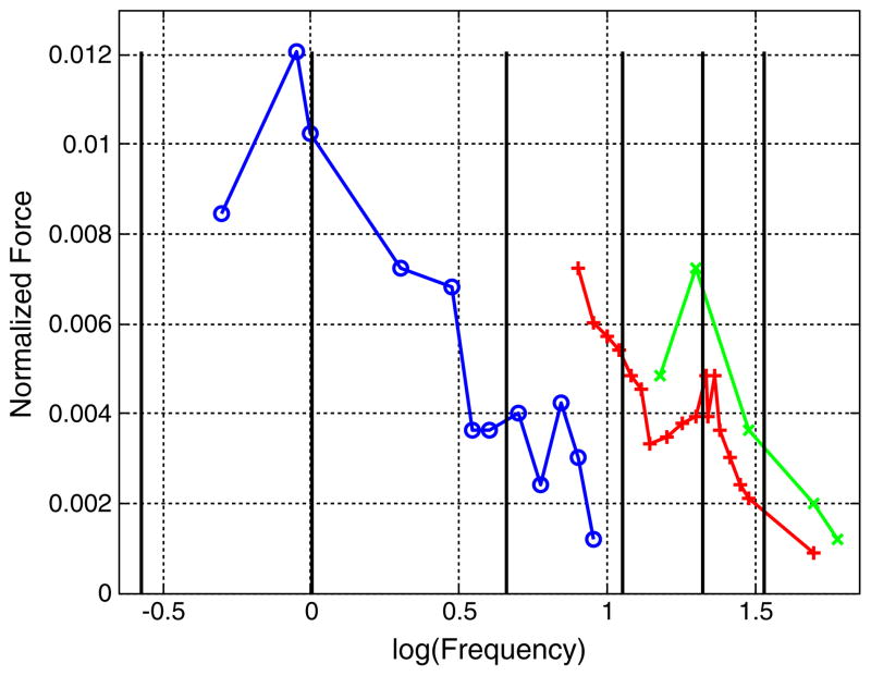
Swimming results for tail II. Each cross mark represents data point from the experiment. The coil driving currents were: 2.39 mApp (blue circle), 4.79 mApp (red plus) and 7.19 mApp (green cross). The vertical solid black lines denote the natural frequencies calculated from the model
Fig. 14.
The swimming results for tail III. Each cross mark represents a data point from the experiment. The coil driving currents were: 2.48 mApp (blue circle), 4.96 mApp (red plus) and 7.44 mApp (green cross). The vertical solid black lines designate the natural frequencies calculated from the model
Fig. 15.
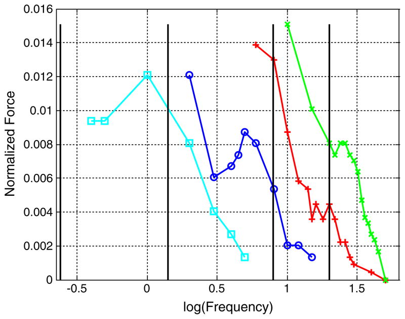
Swimming results for a tail IV. Each cross mark represents a data point from the experiment. The coil driving currents were: 2.39 mApp (cyan square), 4.79 mApp (blue circle), 7.19 mApp (red plus) and 9.59 mApp (green cross). The vertical solid black lines denote the natural frequencies calculated from the model
Fig. 16.
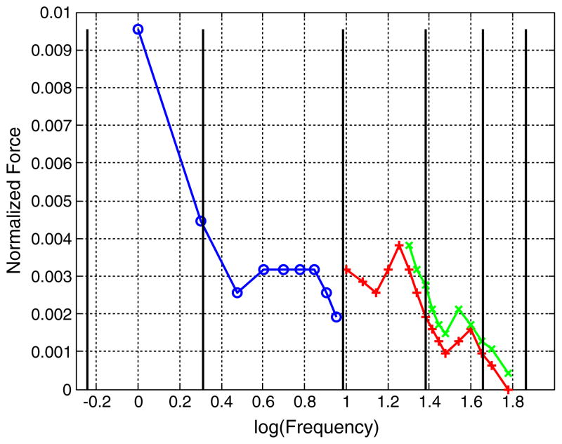
Swimming results for tail V. Each cross mark represents a data point from the experiment. The coil driving currents were: 12.19 mApp (blue circle), 24.39 mApp (red plus) and 36.58 mApp (green cross). The vertical solid black lines denote the natural frequencies calculated from the model
Fig. 17.
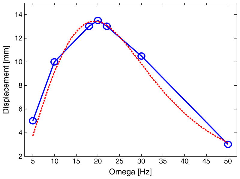
Swimming results for a tail DI. Each circle mark represents a data point from the experiment (average between the forward and backward displacement). The red dashed line is the results of the numerical simulation
Fig. 18.
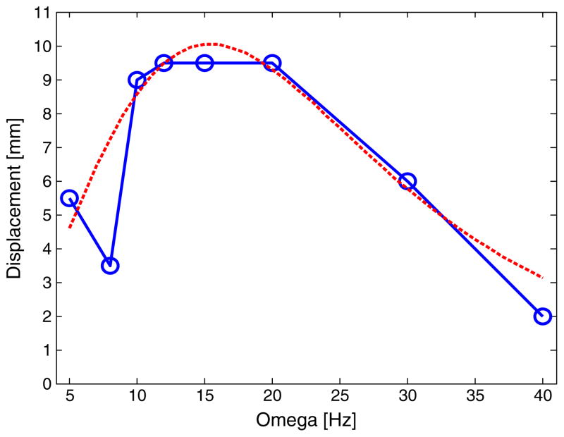
Swimming results for a tail DII. Each circle mark represents a data point from the experiment (average between the forward and backward displacement). The red dashed line is the results of the numerical simulation
Fig. 19.
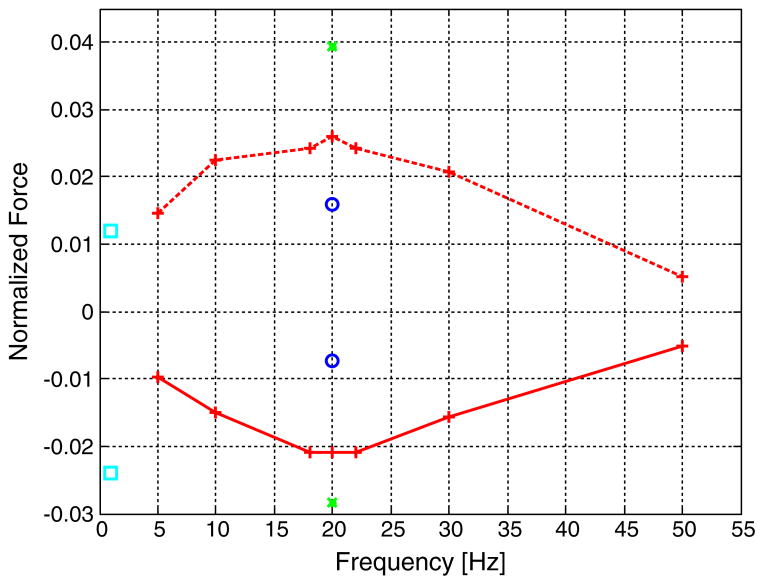
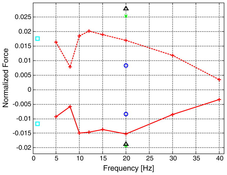
The swimming results for the double coil tail D1. Each cross mark represents a data point from the experiment. The coil driving currents were: 0.9 mApp (cyan square), 4.4 mApp (blue circle), 5.9 mApp (red plus) and 8.7 mApp (green cross). The upper experimental points and dashed line designate 90° phase difference between the coil currents and the lower points with the solid line correspond to 270° phase difference
Fig. 20.
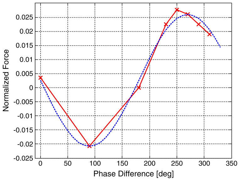
Dependence of the swimming (normalized propulsive force) on the phase difference between the sinusoidal driving currents of the two coils. The dashed line denotes a sinusoidal curve fit to the experimental data
Table 1.
Characteristics and data for each tail. All dimensions are in mm. The differentiating parameters between the tails are highlighted in bold with shaded background
| Tails | I | II | III | IV | V |
|---|---|---|---|---|---|
| Length | 55 | 52 | 51 | 51 | 54 |
| Width | 5 | 6 | 10 | 19 | 2.5 |
| Thickness | 0.06 | 0.06 | 0.06 | 0.06 | 0.06 |
| Coil L. | 3 | 5 | 5 | 5 | 3 |
| Coil W. | 3 | 5 | 5 | 5 | 3 |
| Coil Th. | 0.66 | 0.86 | 0.91 | 0.78 | 0.41 |
| Turns | 50 | 200 | 200 | 200 | 50 |
| Resistance | 7.9 | 41.7 | 40.3 | 41.7 | 8.2 |
| f1 experiment | 0.5 | 0.9 | 0.9 | 1 | 1 |
| f1 theory | 0.59 | 1.40 | 1.01 | 1.4 | 0.57 |
| f2 experiment | 2.5 | 5 | |||
| f2 theory | 2.4 | 2.04 | |||
| f3 experiment | 8 | 7 | 6 | 5 | 10 |
| f3 theory | 8.25 | 7.88 | 4.58 | 7.8 | 9.62 |
| f4 experiment | 20 | 21 | 20 | 20 | 20 |
| f4 theory | 20.12 | 19.97 | 21.09 | 19.97 | 24.23 |
| f5 experiment | 60 | 40 | |||
| f5 theory | 60.1 | 45.60 |
Table 2.
Characteristics for each double coil tail
| Tails | DI | DII |
|---|---|---|
| Length | 23 | 29 |
| Width | 10 | 10 |
| Thickness | 0.127 | 0.127 |
| Coil L. | 5 | 5 |
| Coil W. | 5 | 5 |
| Coil Th. | 0.96 | 0.81 |
| Turns | 100 | 100 |
The influence of the width of the swimming tail. Tail II, III and IV have a 5×5 mm driving coil and widths of 6, 10 and 19 mm respectively. Tail I and V have a 3×3 mm driving coil and widths of 5 and 2.5 mm respectively.
The influence of the size of the driving coil. Tail I and II are have similar size but are driven by a 3×3 and 5×5 mm coil respectively.
The rigid tail experiments examined the influence of the distance between the two coils. The distance between the center of the coils for tail DI and DII were 18 mm and 24 mm respectively (See Table 2).
The tail length and width of tails I–V were chosen to create a low stiffness tail to investigate the single coil swimming method. The length of the tails DI and DII were chosen more in line with a realistic swimming propulsive unit of a capsule endoscope.
The swimming experiment results are presented as force versus frequency (in Hz.) The output force is normalized by the driving input force (Fo/Fi). The output force, Fo, is the propulsive force and it is calculated from the tail displacement in equilibrium and the distance to the hanging point and the weight of the components. Figure 4 illustrates the this equilibrium point (for more details see Kosa et al. 2007). The force is equal to:
| (19) |
cL, cW, and ch are the length, width, and thickness of the coil, L1 and b1 are the length and width of the head section of the swimming tail, Δ is the swimming distance from the hanging wire, and H is the hanging height of the device.
The input force, Fi, is defined as the Lorenz force in each coil. It is the same force we detailed in (13) when the coil is orthogonal to the magnetic field:
| (20) |
Where i0 is the amplitude of the current in the coil. Fi is used for normalization and we defined (20) in order to compare the propulsive force to a well understood quantity for a better insight into the effectiveness of the swimming method.
In section 4.2 we compare the different prototypes in order to examine the influence of the parameters as presented previously in this section. In section 4.3 we examine more thoroughly the results of the elastic tail and compare it to the theoretical model presented in section 2.1. In section 4.4 we compare the swimming results of the double coil tails with the theoretical rigid body model presented in section 2.2. Section 4.5 presents the microdevice’s influence on the MR imaging quality, i.e. the artifacts created by swimming tail.
4.2 Parametric comparison of the microdevices
The influence of the width of the elastic tail on the swimming is summarized in Fig. 10. We compared the normalized force of different tails at the same level of input current and driving frequencies. The comparison points are the peak points of the resonance response in the different microdevices (See Table 1).
In the tails II, III and IV the normalized force remains at the same level at the comparison points. Although the width of the tail increases from 6 mm to 19 mm (216%) the change of normalized force is 1% at 2.39 mA and 1 Hz; 20% at 4.96 mApp and 5 Hz and −37% at 7.19 mApp and 20 Hz. These results indicate that the influence of the width in the tails with the 5×5 mm coil is insignificant.
In the tails I and V there is an increase in the normalized propulsive force when the width is doubled (See Fig. 10). The normalized propulsive force is doubled at 10 Hz, increases by 10% at 20 Hz and by 68% at 35 Hz. Based on the current data we can state that the swimming efficiency is increased by doubling the width although the amount of increase is frequency dependent.
We estimate the influence of the size of the actuator by comparing the absolute propulsive force (19) to the input force (20) in the tails I and II. Figure 11 illustrates the force’s magnitude at the peak of the resonances of the elastic swimming tails. As expected, the level of the propulsive force increases with the input force (not linearly; see following section) and tail II with the 5×5 mm coil achieves higher propulsive forces compared to tail I with the 3×3 mm coil. Even when the input force is similar in the two tails, the propulsive force is different. This different behavior can be explained by change of the resonance frequencies due the different boundary condition (different mass and inertia at x=0).
We can see from the swimming results of the double coil swimmer (See Table 2) that the longer coil DII (29 mm) is less effective compared to the shorter one DI (23 mm). This will be discussed in more details in section 4.4.
When we compare the rigid tails with two coils (DI and DII) to the elastic tails with one coil (I to VI) we can see that the propulsive force created by DI and DII is twice as large as the propulsive force created by the tails with a single coil. It does make sense because the power provided for the tails having two coils are also twice the amount of the power provided for the tail with only one coil. Since both tails can propel a swimming capsule endoscope sufficiently, the choice between them should be made based on the need of the application, like available power and need for maneuverability.
4.3 Elastic swimming tail’s characterization
As shown in Fig. 12, tail I was analyzed most thoroughly. This tail, just as the other microdevices, shows non-linear behavior. This non-linear behavior can be seen from the magnitude of the propulsive force at the same frequency for different input forces. In a linear system the force should be constant after applying the normalization. In our system there is amplification of the swimming force as the input force increases.
Another non-linear phenomenon is the bending of the resonance (Nayfeh and Mook 1979). There is a shift of the maximal response to the softening direction as the input amplitude increases. For example, the third resonance of Tail I is 11 Hz at 12.65 mApp, 10 Hz at 18.98 mApp and 8 Hz at 25.31 mApp.
The main resonances of tail I are: 0.6–0.5 Hz, 2.5–1.8 Hz, 11–8 Hz, 22–19 Hz, 35 Hz, and 60 Hz. The theoretical model could be adjusted to predict the measured natural frequencies very well: 0.59 Hz (0%, no difference), 2.4 Hz (0%), 8.26 Hz (0%), 20.12 Hz (0%), 37.42 Hz (6.7% difference), and 60.133 (0.2% difference). The parameters of the theoretical models were partly derived from the static experiments (EI, m), partly from supplier data and from model estimations (M, J, m̂) and partly by best matching to the experimental data. The parameters of the angular and linear spring attached to the point of the tethering were matched to the experimental data of tail I and the same values were used in the frequency estimation of the other tails. The maximal propulsive force of 71 μN was achieved at 8 Hz, 25mApp.
Figure 13 describes the swimming experiments of tail II, which is similar in size to tail I but has a larger head section with a 5×5 mm coil with 200 turns. The larger head section increases the efficiency of the swimmer. The resonances are similar to tail I (the resonances at higher frequencies cannot be seen). The maximal propulsive force of 153 μN was achieved at 20 Hz, 37.5 mApp.
Comparing tail I and tail II at driving current 12 mApp and 7 mApp at similar frequencies (22 Hz resp. 20 Hz), tail I produces 47 μN and tail II 68 μN, while the theoretical actuation force is 6.66 times higher in tail II.
Figure 14 shows the swimming of tail III in which the width of the tail was increased to 10 mm. The resonances are very similar to tail II, which can also be derived from (10).
The maximal propulsive force of 160.5 μN was achieved at 20 Hz, 7 mApp, similar to tail II. The additional deviations in the natural frequencies may be caused by the inaccuracy of the added mass m̂ estimation at large width.
Figure 15 presents the swimming of tail IV in which the width of the tail was increased to 19 mm. The resonances are very similar to tail II and III although the resonance at 20 Hz is less conspicuous. In tail IV a maximal propulsive force of 431 μN was achieved at 10 Hz, 50 mApp. At 37.5 mApp and 20 Hz the propulsive force is 95.7 μN.
The efficiency of the swimming tails are very similar. After normalization of the propulsive force they are all on the same order of magnitude for all the tails, about 0.01.
Tail V shown in Fig. 16 is a narrower version of tail I. It is less efficient than tail I, and in contrast to the other tails, has a stiffening bending resonance at 20 Hz.
4.4 Double coil swimming tail results
For the double coil swimmers we examined two types that differ by the distance between the centers of the coils (See Table 2). Both of them behave similarly and have a heavily damped main resonance. Tail DI has a resonance at 20 Hz (see Fig. 17) and tail DII has a resonance between 10 and 20 Hz while showing anti-resonance at 8 Hz (see Fig. 18).
The theoretical model matches the swimming results quite accurately. Figures 17 and 18 present the comparisons between the experiments (blue solid lines) and the simulation results for the average distance in forward and backward swimming (red dashed lines) for DI and DII. Each circle mark represents a data point from the experiment (average between the forward and backward displacement). The model matches DI better than DII. The reason is that the theoretical model is based on two rigid bodies and the longer tail has a larger elastic section.
Both tails showed close to symmetrical behavior at 90° and −90° phase difference between the coils driving signals (see Figs. 19 and 21). In addition, we tested the influence of the phase difference between the coil driving signals. The swimming ability can be approximated by a sinusoidal curve as a function of the phase difference between the coil signals (see Fig. 20). This behavior is also seen in the theoretical model described in section 2.2.
Fig. 21.
The swimming results for the double coil tail D2. Each cross mark represents a data point from the experiment. The coil driving currents were: 1.8 mApp (cyan square), 4.4 mApp (blue circle), 5.7 mApp (red), 8.7 mApp (green cross) and 12.4 mApp (black triangle). The upper experimental points and dashed line denote 90° phase difference between the coil currents and the lower points with the solid line correspond to 270° phase difference
Figures 19 and 21 present the normalized propulsive force of the tails DI and DII respectively. The different excitation currents were checked only at 20 Hz. The nonlinear behavior of the double coil tails is similar to the behaviour of the elastic tails investigated in the previous section.
4.5 Artifact experiments
The first set of experiments was designed to test the MRI compatibility of the swimming tail based on standardized MRI-compatibility assessment regulations issued by ASTM International International 2006 and recommended by the United States Food and Drug Administration (FDA) for testing MRI-compatible devices. The standardized test aims to characterize the distortion and signal loss artifacts produced in a MRI instrument by a passive implant (i.e. implants that function without electrical power). In our case, we modified the standardized testing protocol to assess artifacts, and specifically image distortion, introduced by the swimming tail. The second set of experiments was designed to measure the signal-to-noise ratio (SNR) to characterize the effect of the activated swimming tail on image quality. We collected the images using spin echo and gradient echo pulse sequences and utilized the same images for both sets of experiments.
The water tank was placed in the center of the image volume of the MRI device (MAGNETOM Verio 3 T, Siemens) with a surface coil over it. The swimming tail was then immersed into a water tank together with a plastic bar to create a reference void used for the SNR and image distortion study. The bar has a diameter of 25 mm and was placed approximately 50 mm apart from the tail.
The imaging sequence we used were 2-dimensional spin echo imaging (TR 500 ms and TE 20 ms, flip angle 75, echo averaging 2), and gradient echo imaging (TR 500 ms and TE 10 ms, flip angle 90°, echo averaging 2). Axial images were collected using both spin echo and gradient echo sequences but alternating the frequency encoding direction between horizontal and vertical. The images had a matrix size of 256, field of view 200 mm, and slice thickness 3 mm. The locations of the imaging planes were kept the same throughout the acquisitions. Two different frequencies of input currents were used (31.5 Hz and 63 Hz) to investigate related effects. An individual test consists of an image without the presence of the swimming tail in the scanner as the baseline measurement (baseline state), one with the presence of the non-actuated swimming tail and finally with the presence of the actuated tail. The active shimming and center frequency search were performed only once.
Image distortion was assessed by measuring the horizontal and vertical diameters of the reference bar and comparing their average to the baseline state. The SNR against the baseline state was also computed by dividing the mean signal of the central sub-compartment of the water (approximately 25×25 mm2 in size) above the reference bar by the standard deviation of the background noise measured in air (over a region of interest of approximately 25×25 mm2 in size). The ratio of the SNR against the baseline state was computed as 20 log of the ratio.
The presence of a tail coil itself introduced a drop in the SNR by −3.9 dB and an image distortion of 0.4% in the gradient echo images. Table 3 summarizes the results of the MRI compatibility studies of the activated coil indicating SNR drop in the range from −8.5 dB to −5.1 dB depending on the imaging sequence and input current frequencies. The most severe SNR drop of −8.5 dB occurred in spin echo images with the swimming tail activated by 31.5 Hz inputs current. In principle, the distortion ratio ranged from −0.8% to 2.8%, which is negligible and has hardly any clinical impact. One could also see in Table 3 that the spin echo sequence was more susceptible to both image distortion and SNR drop. It also indicates that the image distortion can be up to 2.8%. Note that the image distortion is more significant when the phase encoding was placed along the horizontal direction. Overall, no apparent difference in image degradation has been found when the alternating input current frequency was changed from 31.5 Hz to 63 Hz.
Table 3.
Signal to noise ratio and image distortion for spin and gradient echo images respectively
| Table 3 | Signal to Noise Ratio (20 log) | Image Distortion | |
|---|---|---|---|
| Spin echo images | 31.5 Hz | −8.5 dB | Horizontal 2.8% Vertical −0.4% |
| 63 Hz | −8.0 dB | Horizontal 2.6% Vertical −0.8% |
|
| Gradient echo images | 31.5 Hz | −5.4 dB | Horizontal 1.0% Vertical 0.0% |
| 63 Hz | −5.1 dB | Horizontal 1.0% Vertical 0.0% |
Representative spin echo and gradient echo images highlighting the image quality change at each state of the swimming tale are presented in Fig. 22. One can observe the shadow artifacts along the direction of the frequency encoding.
Fig. 22.
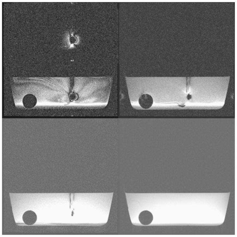
Spin echo (lower) and gradient echo (upper) MRI imaging of the swimming tail inactive (right) and active (left)
5 Discussion
The outcome of the MRI compatibility test showed that the capsule had negligible impact on SNR and image distortion, leading to the conclusion that the capsule, even in an activated state, is MRI compatible. The experiments have also shown that spin echo imaging is more susceptible to noise and distortion by the presence of the capsule. These finding are comparable to other studies on MRI compatible robots and implants (Fischer et al. 2008, Hata et al. 2008).
The swimming experiments show that the system can propel a quite large capsule and is capable of driving it in the body. Using a 1.5 T MRI (compared to 3 T that we are using) will reduce the effectiveness of the microdevice but this loss may be compensated by doubling the input current to the propulsion component. Gradients and field inhomogeneity of the static magnetic field will have little effect on the device because of the sinusoidal input signal that cancels out the forces created by those fields and their magnitude is negligible in the imaging volume of the MRI.
In order to estimate the miniaturization potential of the approach one has to examine the propulsive force and velocity of such an actuator at low Re numbers. The maximal applicable voltage on a magnetic coil scales down by ϕ ∝ s2 (s is a generic geometrical parameter that denotes distance or dimension) because the current density (maximal allowable current divided by the cross section area of the wire measured by A/m2) has to be maintained in the coil. On the other hand the resistance of the coil increases by R ∝ 1/s. Therefore, the amplitude of the current in the coil is proportional to the cube of s: i0 ∝ s3. The Lorenz force that the coils can apply on the tail scales by FL ∝ s3. Analyzing the theoretical model we find that the swimming velocity of this actuator scales down by the square of the geometry, V ∝ s2. This is less favorable compared to other magnetic swimming methods (e.g. Abbott et al. 2009) and piezoelectric traveling wave propulsion V ∝ 1 (Kosa et al. 2007).
The applicability of our swimming method depends on the ability to supply enough power to drive an endoscopic capsule for a operation period of an hour. In order to produce a 0.2 mN propulsive force, tail DII needs 0.4 mW power. As mentioned in the introduction we already showed theoretically that such power can be provided by electro-magnetic induction. Another possibility is using non-magnetic batteries. A miniature zinc-air battery (for example Duracell DA10: φ5.8 mm×3.6 mm) can provide 21 mW for 6 h. We need three tails to steer an endoscopic capsule therefore the power consumption of the propulsive system will be 5% of the power supply.
Nevertheless, the magnetic fields of the MRI (B0 and B1) make our method a desired option for un-tethered propulsion method in an MRI device. For example the propulsive force that was achieved by piezoelectric bi-morph actuators is 0.04 mN (Kosa et al. 2007) whereas here we achieved nearly one order of magnitude higher propulsive force of 0.2 mN (DII coil at 20 Hz, 3 mA driving signal). The power required by a swimming endoscopic capsules depends on its drag.
We showed earlier (Kosa et al. 2008a, b, Kosa and Szekely 2010) that combining three piezoelectric swimming tails will provide sufficient propulsion to swim in the body. The propulsive force of a magnetic tail is one order of magnitude higher than a piezoelectric one thus this device will be able swim effectively.
6 Conclusions
In this study we modeled, designed and tested a fluidic microdevice that can propel a capsule intra-corporal in an MRI magnet. We characterized two swimming methods. One using a single magnetic coil to create propulsion by the undulating motion of an elastic tail. Another tail with a double coil that moves forward and backward by changing the phase difference between the coils. In water, the coils created high propulsive force of about 430 μN in the largest tails.
Acknowledgments
This publication was made possible by grant number 5P41RR019703, 5P01CA067165 from the National Institutes of Health. The authors would like to thank Center for Integration of Medicine and Innovative Technology (CIMIT) for the generous funding of this project and Dr. Gregory Zilman for his helpful suggestion to include the added mass in the elastic model.
Contributor Information
Gábor Kósa, Email: gkosa@post.tau.ac.il, School of Mechanical Engineering, Faculty of Engineering, Tel Aviv University, Tel Aviv, Israel.
Péter Jakab, Department of Radiology, Brigham and Women’s Hospital and Harvard Medical School, Boston, MA, USA.
Gábor Székely, Department of Information Technology and Electrical Engineering, ETH Zurich, Zurich, Switzerland.
Nobuhiko Hata, Department of Radiology, Brigham and Women’s Hospital and Harvard Medical School, Boston, MA, USA.
References
- Abbott JJ, Peyer KE, Lagomarsino MC, Zhang L, Dong L, Kaliakatsos IK, Nelson BJ. Int J Robot Res. 2009;28:1434–1447. [Google Scholar]
- Behkam B, Sitti M. Appl Phys Lett. 2008;93:223901. [Google Scholar]
- Bell DJ, Leutenegger S, Hammar KM, Dong LX, Nelson BJ. IEEE International Conference on Robotics and Automation. 2007:1128–1133. [Google Scholar]
- Berris M, Shoham M. Comput Aided Surg. 2006;11:175–180. doi: 10.3109/10929080600931579. [DOI] [PubMed] [Google Scholar]
- Dreyfus R, Baudry J, Roper ML, Fermigier M, Stone HA, Bibette J. Nature. 2005;437:862–865. doi: 10.1038/nature04090. [DOI] [PubMed] [Google Scholar]
- Ekeberg Ö. Biol Cybern. 1993;69:363–374. [Google Scholar]
- Fischer GS, Iordachita I, Csoma C, Tokuda J, DiMaio SP, Tempany CM, Hata N, Fichtinger G. IEEE ASME Trans Mechatron. 2008;13:295–305. doi: 10.1109/TMECH.2008.924044. [DOI] [PMC free article] [PubMed] [Google Scholar]
- Guo S, Pan Q, Khamesee M. Microsystem Technologies. 2008;14:307–314. [Google Scholar]
- Guo SX, Ge YM, Li LF, Liu S. IEEE ICMA 2006: Proceeding of the 2006 IEEE International Conference on Mechatronics and Automation. Proceedings; 2006. pp. 249–254. [Google Scholar]
- Hata N, Tokuda J, Hurwitz S, Morikawa S. J Magn Reson Imaging. 2008;27:1130–1138. doi: 10.1002/jmri.21314. [DOI] [PMC free article] [PubMed] [Google Scholar]
- Honda T, Arai KI, Ishiyama K. Magnetics IEEE Transactions on Magnetics. 1996;32:5085–5087. [Google Scholar]
- A. International. Standard Test Method for Evaluation of MR Image Artifacts from Passive Implants. 2006;F 2119 – 01 [Google Scholar]
- Kosa G. Micro Robots for Medical Applications. In: Hannaford B, Satava R, Rosen J, editors. Surgical Robotics - Systems, Applications, and Visions. Vol. 2010. 2010. [Google Scholar]
- Kosa G, Jakab P, Hata N, Jolesz F, Neubach Z, Shoham M, Zaaroor M, Szekely G. Biomedical Robotics and Biomechatronics, 2008. BioRob 2008; Proceedings of the 2nd IEEE RAS & EMBS International Conference on; 2008a. pp. 258–263. [Google Scholar]
- Kosa G, Jakab P, Jolesz F, Hata N. Robotics and Automation, 2008. ICRA 2008; IEEE International Conference on; 2008b. pp. 2922–2927. [Google Scholar]
- Kosa G, Shoham M, Zaaroor M. IEEE Trans Robot. 2007;23:137–150. [Google Scholar]
- Kosa G, Szekely G. Hamlyn Symposium for Medical Robotics; London. 2010. [Google Scholar]
- Lauga E. Physical Review E. 2007;75:041916. doi: 10.1103/PhysRevE.75.041916. [DOI] [PubMed] [Google Scholar]
- Liu W, Jia X, Wang F, Jia Z. Sensor Actuator Phys. 2010;160:101–108. [Google Scholar]
- Martel S, Felfoul O, Mathieu JB, Chanu A, Tamaz S, Mohammadi M, Mankiewicz M, Tabatabaei N. Int J Robot Res. 2009;28:1169–1182. doi: 10.1177/0278364908104855. [DOI] [PMC free article] [PubMed] [Google Scholar]
- Mathieu JB, Beaudoin G, Martel S. Biomedical Engineering IEEE Transactions on Biomedical Engineering. 2006;53:292–299. doi: 10.1109/TBME.2005.862570. [DOI] [PubMed] [Google Scholar]
- Mathieu JB, Martel S, Yahia LH, Soulez G, Beaudoin G Engineering in Medicine and Biology Society. 2003 Proceedings of the 25th Annual International Conference of the IEEE Engineering in Medicine and Biology Society. 2003;4:3419–3422. doi: 10.1109/IEMBS.2004.1403342. [DOI] [PubMed] [Google Scholar]
- Meirovitch L. Elements of Vibration Analysis. Tokyo: McGraw-Hill; 1975. [Google Scholar]
- Menciassi A, Valdastri P, Harada K, Dario P. Biomedical Robotics and Biomechatronics, 2008. BioRob 2008; Proceedings of the 2nd IEEE RAS & EMBS International Conference on Biomedical Robotics and Biomechatronics; 2008. pp. 238–243. [Google Scholar]
- Moglia A, Menciassi A, Schurr MO, Dario P. Biomed Microdevices. 2007;9:235–243. doi: 10.1007/s10544-006-9025-3. [DOI] [PubMed] [Google Scholar]
- Nayfeh AC, Mook DT. Nonlinear Oscillations. New York: Wiley and Sons; 1979. [Google Scholar]
- Nelson BJ, Kaliakatsos IK, Abbott JJ. Annu Rev Biomed Eng. 2010;12:55–85. doi: 10.1146/annurev-bioeng-010510-103409. [DOI] [PubMed] [Google Scholar]
- Pouponneau P, Leroux JC, Soulez G, Gaboury L, Martel S. Biomaterials. 2011;32:3481–3486. doi: 10.1016/j.biomaterials.2010.12.059. [DOI] [PubMed] [Google Scholar]
- Sendoh M, Ishiyama K, Arai KI. Magnetics IEEE Transactions on Magnetics. 2003;39:3232–3234. [Google Scholar]
- Yesin KB, Vollmers K, Nelson BJ. Int J Rob Res. 2006;25:527–536. [Google Scholar]
- Yi Z, Qimin W, Peiqiang Z, Xiaohua W, Tao M. Intelligent Robots and Systems, 2004. (IROS 2004). Proceedings. 2004 IEEE/RSJ International Conference on; 2004. pp. 1746–1750. [Google Scholar]
- Zhang L, Abbott JJ, Dong L, Peyer KE, Kratochvil BE, Zhang H, Bergeles C, Nelson BJ. Nano Lett. 2009;9:3663–3667. doi: 10.1021/nl901869j. [DOI] [PubMed] [Google Scholar]


