Abstract
Scanning laser ophthalmoscopy (SLO) and optical coherence tomography (OCT) are widely used retinal imaging modalities that can assist in the diagnosis of retinal pathologies. The combination of SLO and OCT provides a more comprehensive imaging system and a method to register OCT images to produce motion corrected retinal volumes. While high quality, bench-top SLO-OCT systems have been discussed in the literature and are available commercially, there are currently no handheld designs. We describe the first design and fabrication of a handheld SLO/spectral domain OCT probe. SLO and OCT images were acquired simultaneously with a combined power under the ANSI limit. High signal-to-noise ratio SLO and OCT images were acquired simultaneously from a normal subject with visible motion artifacts. Fully automated motion estimation methods were performed in post-processing to correct for the inter- and intra-frame motion in SLO images and their concurrently acquired OCT volumes. The resulting set of reconstructed SLO images and the OCT volume were without visible motion artifacts. At a reduced field of view, the SLO resolved parafoveal cones without adaptive optics at a retinal eccentricity of 11° in subjects with good ocular optics. This system may be especially useful for imaging young children and subjects with less stable fixation.
OCIS codes: (170.4460) Ophthalmic optics and devices, (080.3620) Lens system design, (170.0110) Imaging systems, (170.5755) Retina scanning, (170.4470) Ophthalmology, (110.4500) Optical coherence tomography, (110.4153) Motion estimation and optical flow
1. Introduction
Scanning laser ophthalmoscopy (SLO) and optical coherence tomography (OCT) are widely used retinal imaging modalities that can assist in the diagnosis of retinal pathologies. SLO is a confocal imaging technique that produces real-time, high contrast 2-D en-face retinal images by raster scanning illumination and detecting backscattered light through a pinhole [1]. OCT, like SLO, utilizes raster scanning and confocal detection but also employs coherence gating in the axial direction, which allows for high resolution depth sectioning [2]. Current-generation clinical spectral domain OCT (SD-OCT) systems utilize rapid acquisition along the depth axis (depth-priority scanning) at 20 - 50 kHz line rates to produce high-resolution 2-D cross-sectional images (B-scans) near video rate; however, 3-D volumes comprising hundreds of B-scans require several seconds to acquire. Thus, SD-OCT volumes are typically compromised by patient motion artifacts, particularly in the direction perpendicular to B-scan acquisition [3, 4]. In contrast, current-generation SLO systems utilize rapid acquisition along the lateral axis (lateral-priority scanning) at multi-kHz rates to obtain 2D en-face retinal images also near video rate. Thus, OCT and SLO provide complimentary lateral image information at different time scales such that when combined, rapidly acquired 2-D en-face SLO images may be used to register volumetric OCT B-scans to correct for patient motion within an OCT volume.
The combination of SLO and OCT was first explored by Podoleanu et al. [5] and further developed by various groups [6–11] in either simultaneous or sequential SLO-OCT imaging. Some of these imaging systems have been translated to the clinic as table-top systems mounted to a patient positioning frame like those used in modern slit-lamps. However, due to the physical size and design of these tabletop systems, imaging is limited to patients who are able to sit in an upright position and fixate for several minutes. Portable, handheld SLO-OCT systems would be useful in acquiring motion-corrected OCT volumes in young children [12], as well as patients that are supine, under anesthesia, or otherwise unable to maintain the required posture and fixation. While compact or handheld SLO systems [13, 14] and handheld OCT systems [15–17] have been described in the literature, no combined, handheld SLO-OCT system has yet been described.
In this paper, we present a handheld probe and system design that acquires high signal-to-noise ratio (SNR) SLO and OCT images simultaneously with patient exposures safely below the ANSI limit [18]. At reduced fields of view (FOVs), we show that the SLO can image parafoveal cones without adaptive optics at a retinal eccentricity of 11° in subjects with good ocular optics. We also demonstrate lateral motion correction of OCT B-scans based on motion estimates determined from concurrently acquired SLO images using a modified version of the patch-based cross correlation image registration technique [19–26]. Finally, we demonstrate axial motion correction utilizing a significantly modified version of the automated segmentation-based OCT volume registration technique [27].
2. Methods
The handheld SLO-OCT probe was designed to meet the following six design considerations: 1) simultaneously image with SLO and OCT at a combined power under the ANSI limit, 2) span a 20° FOV with diffraction limited resolution, 3) operate at a minimum of 16 frames per second (fps) with at least 500 x 500 pixel images for both SLO and OCT, 4) have a working distance of approximately 25 mm and a minimal device form factor, 5) compensate for ± 8 diopters of spherical equivalent refractive error, and 6) weigh less than 1.5 kg. Subsections 2.1 - 2.3 describe how we addressed these goals through the optical and mechanical design of the handheld probe. Subsection 2.4 describes all image processing techniques utilized to correct for motion in both the SLO and OCT images.
2.1 System design
The SLO and OCT sources were superluminescent diodes (SLDs) operating at 770 ± 8 nm (Inphenix, Livermore, CA) and 840 ± 35 nm (Superlum, Moscow, Russia), respectively. The system design for the SLO is similar to that in a previous publication [13]. The detector for the SLO was an APD (C5460, Hamamatsu, Shizuoka-ken, Japan) with fixed gain, and the detected signal was low-pass filtered from DC - 2 MHz (Model 3945, Krohn-hite Corporation, Brockton, MA) and acquired at 5 MS/s using the NI PCI 6115 card (12-bit) (National Instruments, Austin, TX). The SLO signal was low-pass filtered with a cutoff frequency of 2 MHz (just less than half the sampling frequency) in order to avoid aliasing artifacts in the SLO image. The SLO scanners consisted of a 4 kHz resonant scanner (Electro-Optical Products Corp, Glendale, NY) and a 5 mm aperture galvanometer (Thorlabs Inc, Newton, NJ) placed as close as mechanically possible without risking damage to the scanners (~8 mm). The horizontal or fast scanner operated at 4.24 kHz, but both the forward and backward sweep of the scanner were utilized to effectively operate at 8.48 kHz. The vertical or slow scanner of the SLO operated at a rate of 16 Hz to record frames at 16 fps. Each image of the SLO consisted of 530 x 580 pixels. The OCT scanners consisted of a commercially available, mounted XY galvanometer set with 3 mm aperture mirrors (Cambridge Technology Inc, Bedford, MA). The integration time per A-scan was 50 μs with 2048 pixels per A-scan. For imaging, we used 500 A-scans per B-scan, 500 B-scans per volume, and a delay equivalent to 50 A-scan integration times per return path (fly-back) of the galvanometer mirrors between B-scans. This corresponded to a fast scan of 40 Hz and a slow scan of ~0.073 Hz giving ~220 SLO images per OCT volume. The SLO scanners were controlled separately with an NI PCI 6711 card (12 bit) (National Instruments, Austin, TX) and the OCT scanners were controlled with the NI PCI 6115 card. Custom software developed in Labview (National Instruments, Austin, TX) and software used in commercially available Bioptigen SDOCT systems (Bioptigen Inc, Durham, NC; see author disclosures in acknowledgments section) were used on the same computer for real-time display of SLO and OCT images. An 80:20 fiber coupler was used for the OCT interferometer and a commercial spectrometer (SD800, Bioptigen Inc, Durham NC) was used as the OCT detector. The OCT axial resolution and 6 dB falloff range were measured to be 7 µm (in air) and 1.1 mm, respectively.
2.2 Probe optical design
The optical design and system optimization for both SLO and OCT sub-systems of the handheld probe were completed using optical design software (Radiant ZEMAX LLC, Redmond, WA). Given the six design considerations mentioned previously, mechanical constraints, and commercially available lenses, the optical design was optimized by minimizing spot sizes spanning the FOV at intermediate image planes and along the retina of a model eye. An overview of the optimized optical design of the handheld system is shown in Fig. 1 . The SLO and OCT beam paths begin separately and are scanned with separate scanners. The beams were combined at a dichroic mirror just prior to the objective lens. The dichroic mirror was placed in this location for two main reasons: 1) the dichroic mirror was designed to work at an angle of incidence of 45° which, after scanning, only occurs between the lenses of the telescope after the scanners, and 2) there was no other location that the dichroic mirror would mechanically fit without increasing device size. Unity beam magnification was employed for both the SLO and OCT systems when imaging the scanners onto the eye’s pupil. The beam diameter at the pupil of the eye was ~2.5 mm for both the SLO and OCT. The telescope prior to the eye consisted of 2.54 cm diameter lenses with an effective focal length of 37.5 mm. This focal length was chosen to give a working distance of ~25 mm and have sufficient room for the dichroic mirror and OCT fold mirror. Since the f-numbers of the lenses are small given the 20° scan range and the bandwidths of the light sources are relatively wide, careful consideration was taken in choosing a combination of commercially available lenses to minimize both spherical and chromatic aberration. Our solution was to use achromatic doublet lenses to reduce chromatic aberration and split the lens with a 3 to 5 ratio in refractive power in order to gradually refract the scanned beams and thus reduce spherical aberration. For the confocal pinhole, we used a multimode fiber with a diameter equal to approximately 1.6 times the Airy disc diameter, which has been demonstrated to give a good balance between image sharpness and throughput [13, 28]. To achieve a confocal pinhole of this size given a 3 mm collection pupil (undilated), a 50 mm focal length collection lens and a 50 μm diameter multimode fiber was utilized.
Fig. 1.
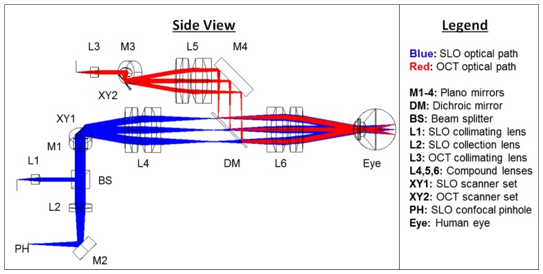
A side view schematic of the handheld SLO-OCT design. All optical components are labeled and described in the legend. The SLO source is a 770 nm SLD with 15 nm bandwidth. The OCT source is an 840 nm SLD with 70 nm bandwidth. The optical paths shown are the superposition of both the illumination and collection paths. The illumination beam diameters for both SLO and OCT were ~2.5 mm. The collection beam diameter for the SLO was larger due to the larger NA and size of the collection fiber, and because backscattered light from the retina fills the pupil in the return path.
Nearly diffraction-limited performance of 7 and 7.5 μm was achieved in Zemax for nine points spanning a common 20° FOV at the back of a model eye for the SLO and OCT systems, respectively (Fig. 2 ). The eye model was created based on parameters determined in a study by Goncharov and Dainty [29].
Fig. 2.
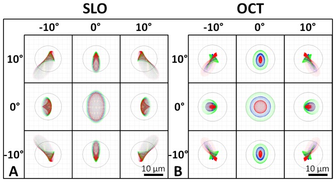
Spot diagrams for the SLO (A) and the OCT (B) illumination on the retina spanning a 20° FOV. SLO and OCT are nearly diffraction limited at 7 and 7.5 µm (the Airy disk radii), respectively (Airy disk is shown by black circle on spot diagrams). Spot diagrams are color coded for 3 wavelengths spanning the bandwidth of the respective sources. SLO spot diagrams have increased astigmatism compared to OCT spot diagrams due to the transmission through the tilted dichroic mirror.
2.3 Probe mechanical design
The opto-mechanical design for the system was developed in Solidworks (Dassault Systèmes SolidWorks Corp, Concord, MA) and is shown with and without its outer casing in Fig. 3 . Custom lens tubes, lens spacers, and mirror mounts were designed and fabricated to accommodate the closely spaced optics of the system and minimize its footprint. The internal skeleton and other structural components were made of aluminum to simplify fabrication and maintain low weight. Alignment pins were used at the junctions between mechanical components to facilitate assembly. Zemax was used to determine the maximum permissible positional error of optical components, and a mechanical tolerance stack analysis was performed to ensure that the design specifications were satisfied. The minimum number of adjustments in the design to optimize performance at assembly and operation was determined, resulting in adjustability of the axial position of the objective lens, the XYZ position of the collection and illumination fibers, and the angular orientation of the resonant scanner. The lens closest to the eye (L6) was mounted on a rack and pinion linear motion system with a total travel of 23 mm to allow for refraction correction of ± 8 diopters. The OCT collimation optics and the SLO collimation and collection optics were adjusted for lateral beam placement using XY translation stages and axial beam placement by sliding the optics along cage rods. The resonant scanner was attached to the main body of the handheld probe via an L-bracket with curved slots to adjust the rotation of the scanner while maintaining the correct center of rotation. The outer casing was 3D printed (Dimension 1200es, Stratasys, Ltd., Edina MN) with Acrylonitrile Butadiene Styrene and consisted of two halves that joined together as a snap fit and could be secured with four set screws. The fabricated setup is shown in Fig. 4 both mounted to a slitlamp-type patient interface configuration with a chin rest for alignment as well as in handheld operation. A rubber eyecup was attached to the last lens of the handheld to aid in keeping the eye a working distance away from the lens. The handheld probe weighed 1.45 kg and was 25.4 cm long x 10.9 cm wide x 15.5 cm tall.
Fig. 3.
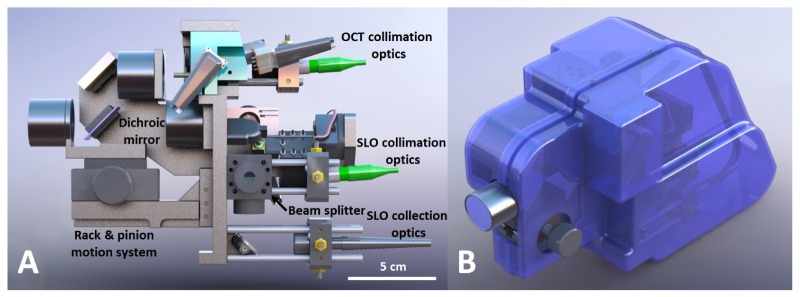
Solidworks design of the handheld SLO-OCT probe. A) Side view showing the internal components of the probe. B) Isometric view of probe with case. Rotatable three-dimensional versions of these figures are included as Media 1 (12.1MB, PDF) (3D PDF) and Media 2 (12.7MB, PDF) (3D PDF) [alternate version available in U3D format as Media 3 (19.2MB, U3D) and Media 4 (20MB, U3D) ].
Fig. 4.
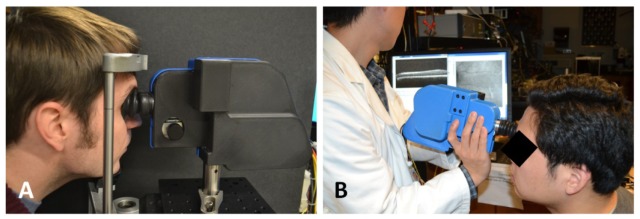
The handheld SLO-OCT probe. A) Tabletop mountable configuration on a patient positioning system from a Carl Zeiss slit-lamp. B) Handheld use of probe.
2.4 Image processing
The lateral motion of the patient’s retina during combined SLO-OCT operation was determined in post-processing after data acquisition by registration of SLO images. First, background measurements taken prior to SLO and OCT image acquisition were subtracted from SLO and OCT images in order to remove any static lens reflections and artifacts due to dust or scratches on optical elements. Then SLO images were preprocessed using a multi-scale coupled Laplacian of Gaussian (LoG) and Gabor filtering technique similar to that described by Estrada et al. [30]. LoG and Gabor filtering were applied to enhance the vessel contrast of fundus images and thus improve the accuracy and robustness of image registration [30, 31]. A LoG filter is a Gaussian filter convolved with a Laplacian filter and can be used to isotropically enhance edges while smoothing the image to reduce noise. Images were convolved with two LoG filters with kernels of size 100 x 100 pixels with standard deviation values of 1.5 and 3 pixels, respectively. The maximum response was kept at each pixel for the two LoG filtered images and the resulting image was further filtered with Gabor filters to enhance vessel-like structures. A Gabor filter is a Gaussian filter modulated by a sinusoid and can be used to enhance edges of a predefined length at the orientation of the sinusoid. Gabor filters are defined with the following five parameters: 1) standard deviation of the Gaussian along the sinusoid (), 2) standard deviation of the Gaussian orthogonal to the sinusoid (), 3) spatial frequency of the sinusoid (v), 4) phase of the sinusoid (ψ), and 5) orientation of the sinusoid (θ). We reduced the Gabor filter to just two parameters ( and θ) by setting to 8 pixels, ψ to 0°, and v to . We then applied 30 Gabor filters with kernels of size 100 x 100 pixels to our LoG filtered image with equal to 2, 5, and 8 pixels, respectively, at 10 orientations spanning 180°. The maximum response was kept at each pixel for the 30 Gabor filtered images and, in the resulting image, pixels with intensities less than 5% of the maximum intensity were set to zero by thresholding.
Preprocessed SLO images were then registered using a modified version of the patch-based cross correlation technique [19–26]. Each preprocessed SLO frame was divided into 15 horizontal strips (14 strips with 35 x 580 pixels each and 1 strip with 40 x 580 pixels). All strips were cross-correlated to a reference frame (usually the first acquired frame) in order to determine the (x,y) displacements of each strip. Since frames were acquired at 16 fps, images were divided into 15 strips to obtain 240 lateral motion estimates per second. Image rotation was assumed negligible per strip but was determined per frame. This was done by setting the initial or reference frame to have 0° rotation, rotating each successive SLO frame with a set of 20 rotations spanning ± 0.5° about the rotation of the previous frame, cross correlating with the reference frame, and keeping the rotation value resulting in the highest cross correlation peak. This range and step size for rotations was chosen because, in practice, the rotation between successive frames was much less than ± 0.5° and a rotation of an SLO image by a single step size (0.05°) was indistinguishable from no rotation. Blinks were detected by monitoring when the average pixel intensity in the unprocessed SLO image fell below 5% of the average pixel intensity in the reference SLO image. Both SLO and OCT frames corresponding to blinks were discarded from the raw data. After patch-based cross correlation was completed for a set of SLO data, the full motion field of each SLO image was found by spline interpolation of the estimated motion. Each individual line of an SLO image was warped using this motion field to correct for motion artifacts.
The motion estimates from SLO image registration were then applied to correct for lateral motion artifacts in the simultaneously acquired OCT volumes. Since the OCT scanners spanned the same FOV as the SLO scanners, the OCT motion was determined by multiplying the SLO motion by the ratio between the OCT lateral pixel dimensions and the SLO lateral pixel dimensions. The bulk lateral displacement between OCT volumes was determined by taking an en-face summed voxel projection (SVP) of each lateral motion-corrected OCT volume, interpolating gaps in the SVPs up to 4 x 4 pixels in size where data was not captured, preprocessing the interpolated SVPs with LoG/Gabor filters, and cross correlating the filtered SVPs to get the lateral motion and rotation between volumes. Composite SVPs were created by shifting and rotating the individual lateral-motion corrected SVPs by the previously calculated bulk lateral displacement and rotation, averaging the overlapping pixels containing data, and interpolating gaps in the composite SVP with the same method described for interpolating individual SVPs.
To correct for axial motion during the OCT volume acquisition, we utilized a significantly modified version of the automated segmentation-based volumetric image registration technique [27], which incorporates the orthogonal scanning technique also utilized in other publications [32, 33]. Orthogonal acquisition was accomplished by taking OCT data in two modes: 1) with the horizontal scanner as the fast scanner (X-fast) and 2) with the vertical scanner as the fast scanner (Y-fast). In our new method, first the internal limiting membrane (ILM) of the retina in each B-scan for both X-fast and Y-fast OCT volumes was automatically segmented through preprocessing and thresholding. Preprocessing involved median filtering the image with a 25 x 25 pixel kernel and convolving with 20 directional filters with kernels of size 30 x 20 pixels spanning 180°. Directional filters were created by simply rotating kernels with values of 1 and −1 for the top and bottom halves of the kernel. The maximum response for each pixel in the B-scan was obtained after convolution with all directional filters in order to enhance edges with different orientations. Individual A-scans in the preprocessed B-scans were then thresholded to find the first retinal border in the image, which corresponds to the ILM. The result was smoothed for all A-scans per B-scan to allow for a continuous segmentation.
After segmentation, lateral motion-corrected OCT volumes were overlapped to create the initial composite OCT volume. Two X-fast and two Y-fast B-scans near the corners of the composite OCT volume were then axially translated and rotated such that the segmented ILM in each B-scan overlapped axially for points of lateral overlap. Remaining X-fast B-scans were then also registered by axial translation and rotation such that the segmented ILM overlapped axially at points of lateral overlap in the two initial Y-fast B-scans. The same was done for the remaining Y-fast B-scans with respect to the two initial X-fast B-scans to complete axial registration of the composite OCT volume. Regions in the composite volume with overlapping A-scans were averaged to improve SNR.
2.5 Ethical considerations
The use of our experimental setup for in vivo measurements in humans was approved by the local Institutional Review Board and adhered to the tenets of the Declaration of Helsinki. Informed consent was obtained from each subject.
3. Results
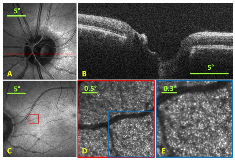
SLO and OCT images were acquired simultaneously spanning a 20° FOV at 16 and 40 fps, respectively (as shown in A and B of Fig. 5 ). Background measurements taken prior to imaging were subtracted from both SLO and OCT images to remove static artifacts like lens reflections and scratches or dust on optical elements. The SNR of the OCT system was determined by measuring the maximum signal from an A-scan when the optical beam was reflected from a mirror divided by the background noise level of the system. To avoid saturation of the spectrometer, neutral density filters were added into the sample arm and the maximum A-scan signal detected was compensated to account for this additional loss. The SNR of our OCT system was 100 dB for 50 µs integration time and 300 µW illumination power at the sample. The SLO, at smaller FOVs, was shown to visualize parafoveal cones at a retinal eccentricity of 11° without adaptive optics (as shown in C-E of Fig. 5). The average cone spacing at 11° eccentricity is approximately 12.4 µm [34] which is ~1.8 times the diffraction-limited spot size of the SLO arm. The radiant flux incident on the eye for the SLO and OCT were under the ANSI limit at 300 µW each, which comprised 56% and 41% of the thermal hazard maximum permissible exposure limit [18].
Fig. 5.
A) SLO image (single frame) with red line representing location of B-scan. B) Single B-scan taken simultaneously with the SLO at 40 fps. C) Foveal SLO image (single frame) indicating the position where the SLO was optically zoomed to visualize parafoveal cones. D) Optically zoomed retinal image (5 frame average) via reduction of scan range to a 2.5° FOV at location shown by red box in C) at an 11° eccentricity. E) Digitally zoomed image at location shown by blue box in D) with a 1.5° FOV showing the cone photoreceptor mosaic.
SLO images were preprocessed with LoG/Gabor filtering and thresholding as shown in Fig. 6 prior to image registration. Preprocessed SLO images were registered using our modified version of the patch-based cross correlation technique and the motion field generated from registration was used to de-warp SLO images as shown in Fig. 7 .
Fig. 6.
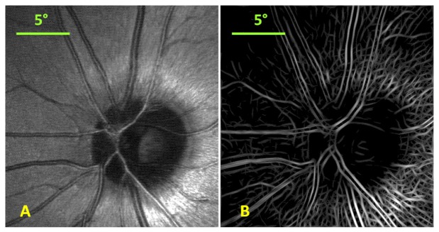
Single frame SLO image (A) and the corresponding LoG/Gabor filtered and thresholded SLO image (B).
Fig. 7.
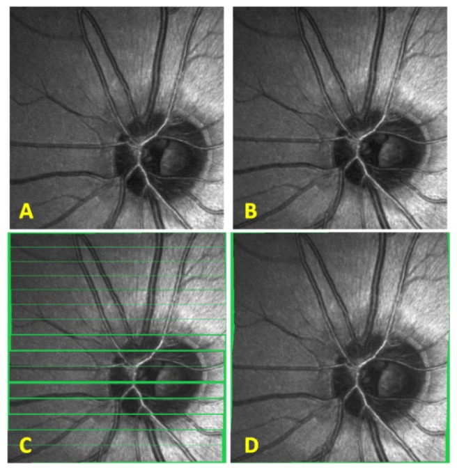
SLO patch-based registration. A) SLO reference frame to which all images are registered. B) Another SLO image from the same subject. C) Patch-based registration of SLO image in B) to the reference frame in A). The voids have been colored in green to better visualize the regions where no information was obtained. D) Spline interpolated motion determined from the patch-based registration in C) is applied to each line in the SLO image from B) and empty voids within the frame are linearly interpolated.
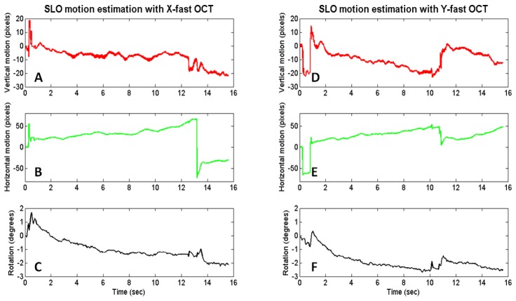
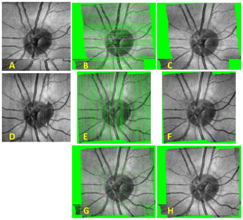
Plots of SLO motion estimation are shown in Fig. 8 for an X-fast and Y-fast OCT volume. SVPs are shown before and after lateral motion correction, combination of X- and Y-fast SVPs, and interpolation in Fig. 9 .
Fig. 8.
SLO motion estimation with X-fast (A-C) and Y-fast (D-F) OCT. A slow horizontal drift is visualized in the X-fast motion estimation with a large saccade captured at around the 13 second point. Both vertical and horizontal drifts are apparent in the Y-fast motion estimation with two microsaccades captured at around the 0.5 and 11 second points.
Fig. 9.
Raw and registered SVPs with and without interpolation based on motion estimation through SLO frame registration. A) Raw X-fast SVP. B) Registered X-fast SVP. C) Registered X-fast SVP after interpolation. D) Raw Y-fast SVP. E) Registered Y-fast SVP. F) Registered Y-fast SVP after interpolation. G) Combined X- and Y-fast SVPs after registration. H) Combined X- and Y-fast SVPs after registration and interpolation.
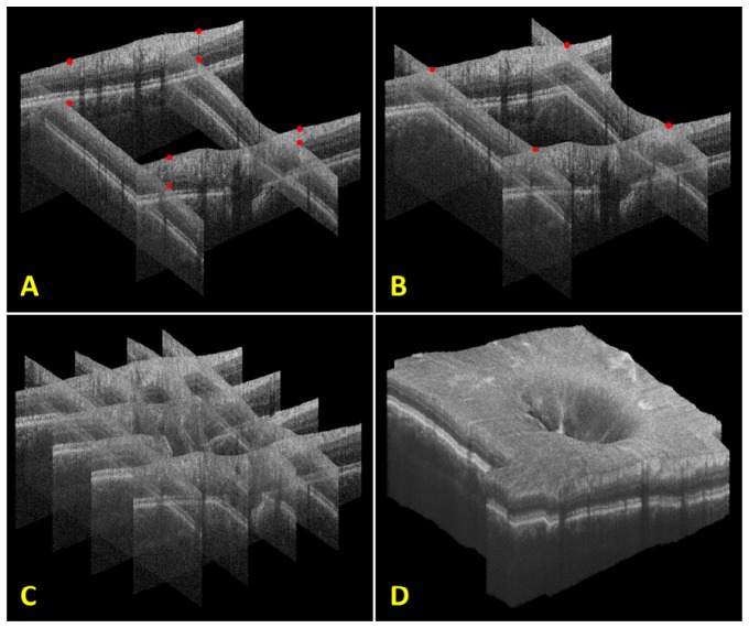
OCT axial motion was determined using our significantly modified version of the automated segmentation-based volumetric image registration technique. A depiction of this procedure and the resulting registered OCT volume are shown in Fig. 10 below.
Fig. 10.
Steps for axial registration with an X- and Y-fast OCT volume. A) The initial four B-scans taken near the corners of the composite volume. Red dots indicate points of lateral overlap on the surface of each initial B-scan. B) The initial four B-scans after axial translation and rotation. Note that the red dots at points of lateral overlap now overlap axially as well. C) The registration of an additional two X- and Y-fast B-scans. D) Final registered volume rendering of all X- and Y-fast B-scans. Orthogonal fly-throughs of this data are included as supplementary material (Media 5 (22.7MB, MPG) ).
4. Discussion
The results described in this paper have demonstrated a handheld SLO-OCT probe capable of imaging with ~7 µm resolution spanning a 20° FOV across the retina. A motion correction algorithm was used to improve the representation of both SLO images and OCT volumes.
One important characteristic of our motion correction algorithm was that it was performed in post-processing as opposed to real-time. The advantage of post-processed or offline motion correction is that more sophisticated, time-consuming algorithms can be applied for registration. This can allow for more robust registration that works well even with large motions, rotations, illumination differences, and SNR differences in acquired images. However, one important drawback is that acquired volumes often have gaps corresponding to regions where data was not acquired due to motion. To overcome this limitation often multiple volumes are acquired and combined. Real-time or online motion correction allows for the OCT scanners to be moved during acquisition to compensate for the motion of the patient using high-speed image registration via the SLO channel [10, 11, 23]. This method avoids gaps of missing data in the acquired volume so a single acquired volume is sufficient. However, in order to accurately compensate for patient motion in real-time, motion correction algorithms usually must be implemented in graphics processing units (GPUs) or Field-Programmable Gate Arrays (FPGAs) [10]. In addition, these algorithms are generally less robust due to: simplifying assumptions applied to preprocessing steps prior to registration, lack of rotation correction, and an unavoidable latency between the measurement and scanner correction that limits the frequency range of correctable motion [10, 23].
For handheld operation of the probe, motion was generally greater than when the probe was in the tabletop mountable configuration. Hand tremor of the operator added significantly to the net motion. The LoG/Gabor preprocessing step included in our algorithm allowed for more robust registration and larger motion correction than possible with cross correlating unprocessed SLO frames, thus yielding accurate motion correction even in handheld operation. An example frame with large motion with respect to the reference frame (5 pixel vertical offset, 250 pixels horizontal offset, and 1.6° rotation) is shown to have more accurate registration with LoG/Gabor preprocessing than without (see Fig. 11 below).
Fig. 11.
Comparison between registration with and without LoG/Gabor preprocessing. A) The reference frame. B) The target frame (to be registered with respect to reference frame). C) LoG/Gabor preprocessed reference frame. D) LoG/Gabor preprocessed target frame. E) Registration of A) and B) without LoG/Gabor preprocessing. F) Registration of A) and B) with the LoG/Gabor preprocessing shown in C) and D).
LoG/Gabor preprocessing in practice provided more robust registration results than without preprocessing but has a potential disadvantage for real-time implementation. In high SNR images with relatively little motion, registration with unprocessed SLO images could provide accurate results, but with lower processing times compared to LoG/Gabor preprocessed images.
The axial registration technique used in our algorithm corrected for both axial translation and rotation of each B-scan while assuming that the lateral position of each A-scan would be as estimated by the lateral motion calculated from the SLO channel. When the rotation of each B-scan is relatively small, lateral motion induced by rotation can be approximated as zero but for large rotations, the lateral movement of A-scans would be significant. In practice, we found that the rotation of B-scans tended to vary by less than ± 5° during a volume acquisition so we neglected the lateral movement of A-scans due to rotation.
5. Conclusion
We have demonstrated an SLO-OCT handheld probe with ~7 µm resolution spanning a 20° FOV across the retina. Parafoveal cone imaging was shown using the SLO arm of this device using a 2.5° FOV at an 11° eccentricity without adaptive optics. SLO motion estimation was achieved using a patch-based cross correlation approach using 15 strips to allow 240 motion estimates per second. OCT lateral registration was demonstrated using the motion estimation from simultaneously acquired SLO images. OCT axial registration was accomplished using a registration technique utilizing orthogonal fast scan directions and the segmentation of the ILM of the retina. Lateral and axial motion correction were both fully automated and allowed for automatic generation of motion corrected OCT volumes. The use of this technology will provide a compact and cost-effective solution for high SNR, motion-corrected imaging of patients that are supine, under anesthesia, or unable to position. These include infants with variety of retinal diseases such as retinopathy of prematurity [12, 35, 36] albinism [37], nystagmus [38], Shaken baby syndrome [15], and for imaging young children.
Acknowledgments
This research was supported by the Hartwell Foundation grants from NIH R21-EY-021321-01A1, NIH R01-EY-014743, NIH P30 EY005722, and the Fitzpatrick Foundation Scholars Fellowship. We would like to thank Dr. Al-Hafeez Dhalla for providing helpful conversations regarding the initial system design, Dr. Ryan McNabb for assistance with the Bioptigen OCT hardware, and Dr. Cynthia A. Toth for providing helpful feedback on the mechanical design. This paper was presented as a poster at the 2013 ARVO Annual Meeting, Seattle WA, May 2013. Dr. Izatt is co-founder and Chief Science Advisor for Bioptigen, Inc. and has corporate, equity, and intellectual property interests (including royalties) in this company. Duke University also equity and intellectual property interests (including royalties) in Bioptigen, Inc.
References and links
- 1.Webb R. H., Hughes G. W., Delori F. C., “Confocal scanning laser ophthalmoscope,” Appl. Opt. 26(8), 1492–1499 (1987). 10.1364/AO.26.001492 [DOI] [PubMed] [Google Scholar]
- 2.Huang D., Swanson E. A., Lin C. P., Schuman J. S., Stinson W. G., Chang W., Hee M. R., Flotte T., Gregory K., Puliafito C. A., et, “Optical coherence tomography,” Science 254(5035), 1178–1181 (1991). 10.1126/science.1957169 [DOI] [PMC free article] [PubMed] [Google Scholar]
- 3.S. Ricco, M. Chen, H. Ishikawa, G. Wollstein, and J. Schuman, “Correcting motion artifacts in retinal spectral domain optical coherence tomography via image registration,” in Medical Image Computing and Computer-Assisted Intervention – MICCAI 2009, G.-Z. Yang, D. Hawkes, D. Rueckert, A. Noble, and C. Taylor, eds. (Springer Berlin / Heidelberg, 2009), pp. 100–107. [DOI] [PMC free article] [PubMed] [Google Scholar]
- 4.M. D. Robinson, S. J. Chiu, C. A. Toth, J. Izatt, J. Y. Lo, and S. Farsiu, “Novel applications of super-resolution in medical imaging,” in “Super-resolution imaging”, P. Milanfar, ed. (CRC Press 2010), pp. 383–412. [Google Scholar]
- 5.Podoleanu A. G., Jackson D. A., “Combined optical coherence tomograph and scanning laser ophthalmoscope,” Electron. Lett. 34(11), 1088–1090 (1998). 10.1049/el:19980793 [DOI] [Google Scholar]
- 6.Hammer D. X., Iftimia N. V., Ustun T. E., Magill J. C., Ferguson R. D., “Dual OCT/SLO imager with three-dimensional tracker,” Proc. SPIE 5688, 33–44 (2005). 10.1117/12.592762 [DOI] [Google Scholar]
- 7.Pircher M., Götzinger E., Sattmann H., Leitgeb R. A., Hitzenberger C. K., “In vivo investigation of human cone photoreceptors with SLO/OCT in combination with 3D motion correction on a cellular level,” Opt. Express 18(13), 13935–13944 (2010). 10.1364/OE.18.013935 [DOI] [PMC free article] [PubMed] [Google Scholar]
- 8.Tao Y. K., Farsiu S., Izatt J. A., “Interlaced spectrally encoded confocal scanning laser ophthalmoscopy and spectral domain optical coherence tomography,” Biomed. Opt. Express 1(2), 431–440 (2010). 10.1364/BOE.1.000431 [DOI] [PMC free article] [PubMed] [Google Scholar]
- 9.Zawadzki R. J., Jones S. M., Pilli S., Balderas-Mata S., Kim D. Y., Olivier S. S., Werner J. S., “Integrated adaptive optics optical coherence tomography and adaptive optics scanning laser ophthalmoscope system for simultaneous cellular resolution in vivo retinal imaging,” Biomed. Opt. Express 2(6), 1674–1686 (2011). 10.1364/BOE.2.001674 [DOI] [PMC free article] [PubMed] [Google Scholar]
- 10.Vienola K. V., Braaf B., Sheehy C. K., Yang Q., Tiruveedhula P., Arathorn D. W., de Boer J. F., Roorda A., “Real-time eye motion compensation for OCT imaging with tracking SLO,” Biomed. Opt. Express 3(11), 2950–2963 (2012). 10.1364/BOE.3.002950 [DOI] [PMC free article] [PubMed] [Google Scholar]
- 11.Braaf B., Vienola K. V., Sheehy C. K., Yang Q., Vermeer K. A., Tiruveedhula P., Arathorn D. W., Roorda A., de Boer J. F., “Real-time eye motion correction in phase-resolved OCT angiography with tracking SLO,” Biomed. Opt. Express 4(1), 51–65 (2013). 10.1364/BOE.4.000051 [DOI] [PMC free article] [PubMed] [Google Scholar]
- 12.Maldonado R. S., O’Connell R. V., Sarin N., Freedman S. F., Wallace D. K., Cotten C. M., Winter K. P., Stinnett S., Chiu S. J., Izatt J. A., Farsiu S., Toth C. A., “Dynamics of human foveal development after premature birth,” Ophthalmology 118(12), 2315–2325 (2011). 10.1016/j.ophtha.2011.05.028 [DOI] [PMC free article] [PubMed] [Google Scholar]
- 13.LaRocca F., Dhalla A.-H., Kelly M. P., Farsiu S., Izatt J. A., “Optimization of confocal scanning laser ophthalmoscope design,” J. Biomed. Opt. 18(7), 076015 (2013). 10.1117/1.JBO.18.7.076015 [DOI] [PMC free article] [PubMed] [Google Scholar]
- 14.Kelly J. P., Weiss A. H., Zhou Q., Schmode S., Dreher A. W., “Imaging a child’s fundus without dilation using a handheld confocal scanning laser ophthalmoscope,” Arch. Ophthalmol. 121(3), 391–396 (2003). 10.1001/archopht.121.3.391 [DOI] [PubMed] [Google Scholar]
- 15.Radhakrishnan S., Rollins A. M., Roth J. E., Yazdanfar S., Westphal V., Bardenstein D. S., Izatt J. A., “Real-time optical coherence tomography of the anterior segment at 1310 nm,” Arch. Ophthalmol. 119(8), 1179–1185 (2001). 10.1001/archopht.119.8.1179 [DOI] [PubMed] [Google Scholar]
- 16.Scott A. W., Farsiu S., Enyedi L. B., Wallace D. K., Toth C. A., “Imaging the infant retina with a hand-held spectral-domain optical coherence tomography device,” Am. J. Ophthalmol. 147(2), 364–373, e2 (2009). 10.1016/j.ajo.2008.08.010 [DOI] [PubMed] [Google Scholar]
- 17.Jung W., Kim J., Jeon M., Chaney E. J., Stewart C. N., Boppart S. A., “Handheld optical coherence tomography scanner for primary care diagnostics,” IEEE Trans. Biomed. Eng. 58(3), 741–744 (2011). 10.1109/TBME.2010.2096816 [DOI] [PMC free article] [PubMed] [Google Scholar]
- 18.Laser Institute of America, American National Standard for Safe Use of Lasers ANSI Z136.1–2007 (American National Standards Institute, Inc., 2007). [Google Scholar]
- 19.Stevenson S. B., Roorda A., “Correcting for miniature eye movements in high resolution scanning laser ophthalmoscopy,” Proc. SPIE 5688, 145–151 (2005). 10.1117/12.591190 [DOI] [Google Scholar]
- 20.Vogel C. R., Arathorn D. W., Roorda A., Parker A., “Retinal motion estimation in adaptive optics scanning laser ophthalmoscopy,” Opt. Express 14(2), 487–497 (2006). 10.1364/OPEX.14.000487 [DOI] [PubMed] [Google Scholar]
- 21.Arathorn D. W., Yang Q., Vogel C. R., Zhang Y., Tiruveedhula P., Roorda A., “Retinally stabilized cone-targeted stimulus delivery,” Opt. Express 15(21), 13731–13744 (2007). 10.1364/OE.15.013731 [DOI] [PubMed] [Google Scholar]
- 22.Yang Q., Arathorn D. W., Tiruveedhula P., Vogel C. R., Roorda A., “Design of an integrated hardware interface for AOSLO image capture and cone-targeted stimulus delivery,” Opt. Express 18(17), 17841–17858 (2010). 10.1364/OE.18.017841 [DOI] [PMC free article] [PubMed] [Google Scholar]
- 23.Sheehy C. K., Yang Q., Arathorn D. W., Tiruveedhula P., de Boer J. F., Roorda A., “High-speed, image-based eye tracking with a scanning laser ophthalmoscope,” Biomed. Opt. Express 3(10), 2611–2622 (2012). 10.1364/BOE.3.002611 [DOI] [PMC free article] [PubMed] [Google Scholar]
- 24.A. Dubra and Z. Harvey, “Registration of 2D Images from Fast Scanning Ophthalmic Instruments,” in Biomedical Image Registration, Vol. 6204 of Lecture Notes in Computer Science (Springer, Berlin), pp. 60–71 (2010). [Google Scholar]
- 25.Faisan S., Lara D., Paterson C., “Scanning ophthalmoscope retinal image registration using one-dimensional deformation fields,” Opt. Express 19(5), 4157–4169 (2011). 10.1364/OE.19.004157 [DOI] [PubMed] [Google Scholar]
- 26.Kocaoglu O. P., Lee S., Jonnal R. S., Wang Q., Herde A. E., Derby J. C., Gao W., Miller D. T., “Imaging cone photoreceptors in three dimensions and in time using ultrahigh resolution optical coherence tomography with adaptive optics,” Biomed. Opt. Express 2(4), 748–763 (2011). 10.1364/BOE.2.000748 [DOI] [PMC free article] [PubMed] [Google Scholar]
- 27.Song X., Estrada R., Chiu S. J., Dhalla A.-H., Toth C. A., Izatt J. A., Farsiu S., “Segmentation-based registration of retinal optical coherence tomography images with pathology,” Invest. Ophthalmol. Vis. Sci. 52, 1309- (2011). [Google Scholar]
- 28.Zhang Y., Poonja S., Roorda A., “MEMS-based adaptive optics scanning laser ophthalmoscopy,” Opt. Lett. 31(9), 1268–1270 (2006). 10.1364/OL.31.001268 [DOI] [PubMed] [Google Scholar]
- 29.Goncharov A. V., Dainty C., “Wide-field schematic eye models with gradient-index lens,” J. Opt. Soc. Am. A 24(8), 2157–2174 (2007). 10.1364/JOSAA.24.002157 [DOI] [PubMed] [Google Scholar]
- 30.Estrada R., Tomasi C., Cabrera M. T., Wallace D. K., Freedman S. F., Farsiu S., “Enhanced video indirect ophthalmoscopy (VIO) via robust mosaicing,” Biomed. Opt. Express 2(10), 2871–2887 (2011). 10.1364/BOE.2.002871 [DOI] [PMC free article] [PubMed] [Google Scholar]
- 31.Hendargo H. C., Estrada R., Chiu S. J., Tomasi C., Farsiu S., Izatt J. A., “Automated non-rigid registration and mosaicing for robust imaging of distinct retinal capillary beds using speckle variance optical coherence tomography,” Biomed. Opt. Express 4(6), 803–821 (2013). 10.1364/BOE.4.000803 [DOI] [PMC free article] [PubMed] [Google Scholar]
- 32.R. J. Zawadzki, A. R. Fuller, S. S. Choi, D. F. Wiley, B. Hamann, and J. S. Werner, “Correction of motion artifacts and scanning beam distortions in 3D ophthalmic optical coherence tomography imaging,” Proc. SPIE 642607–642607 (2007). [Google Scholar]
- 33.Kraus M. F., Potsaid B., Mayer M. A., Bock R., Baumann B., Liu J. J., Hornegger J., Fujimoto J. G., “Motion correction in optical coherence tomography volumes on a per A-scan basis using orthogonal scan patterns,” Biomed. Opt. Express 3(6), 1182–1199 (2012). 10.1364/BOE.3.001182 [DOI] [PMC free article] [PubMed] [Google Scholar]
- 34.Merino D., Duncan J. L., Tiruveedhula P., Roorda A., “Observation of cone and rod photoreceptors in normal subjects and patients using a new generation adaptive optics scanning laser ophthalmoscope,” Biomed. Opt. Express 2(8), 2189–2201 (2011). 10.1364/BOE.2.002189 [DOI] [PMC free article] [PubMed] [Google Scholar]
- 35.Chavala S. H., Farsiu S., Maldonado R., Wallace D. K., Freedman S. F., Toth C. A., “Insights into advanced retinopathy of prematurity using hand-held spectral domain optical coherence tomography imaging,” Ophthalmology 116(12), 2448–2456 (2009). 10.1016/j.ophtha.2009.06.003 [DOI] [PMC free article] [PubMed] [Google Scholar]
- 36.Moreno T. A., O’Connell R. V., Chiu S. J., Farsiu S., Cabrera M. T., Maldonado R. S., Tran-Viet D., Freedman S. F., Wallace D. K., Toth C. A., “Choroid development and feasibility of choroidal imaging in the preterm and term infants utilizing SD-OCT,” Invest. Ophthalmol. Vis. Sci. 54(6), 4140–4147 (2013). 10.1167/iovs.12-11471 [DOI] [PMC free article] [PubMed] [Google Scholar]
- 37.Chong G. T., Farsiu S., Freedman S. F., Sarin N., Koreishi A. F., Izatt J. A., Toth C. A., “Abnormal foveal morphology in ocular albinism imaged with spectral-domain optical coherence tomography,” Arch. Ophthalmol. 127(1), 37–44 (2009). 10.1001/archophthalmol.2008.550 [DOI] [PubMed] [Google Scholar]
- 38.Cronin T. H., Hertle R. W., Ishikawa H., Schuman J. S., “Spectral domain optical coherence tomography for detection of foveal morphology in patients with nystagmus,” J. AAPOS 13(6), 563–566 (2009). 10.1016/j.jaapos.2009.09.019 [DOI] [PMC free article] [PubMed] [Google Scholar]


