Abstract
Fractional photothermolysis induced by non-ablative fractional lasers (NAFLs) or ablative fractional lasers (AFLs) can remodel the skin, regenerate collagen, and remove tumor tissue. However, fractional laser treatments may result in severe side effects, and multiple treatments are required to achieve the expected outcome. Thus, the treatment outcome and downtime after fractional laser treatments are key issues to determine the following treatment strategy. In this study, an optical coherence tomography (OCT) system was implemented for in vivo studies of wound healing after NAFL and AFL treatments. According to the OCT scanning results, the laser-induced photothermolysis including volatilization and coagulation could be morphologically identified. To continue monitoring the wound healing process, the treated regions were scanned with OCT at different time points, and the en-face images at various tissue depths were extracted from three-dimensional OCT images. Furthermore, to quantitatively evaluate the morphological changes at different tissue depths during wound healing, an algorithm was developed to distinguish the backscattering properties of untreated and treated tissues. The results showed that the coagulation damage induced by the NAFLs could be rapidly healed in 6 days. In contrast, the tissue volatilization induced by AFLs required a longer recovery time of 14 days. In conclusion, this study establishes the feasibility of this methodology as a means of clinically monitoring treatment outcomes and wound healing after fractional laser treatments.
OCIS codes: (110.4500) Optical coherence tomography, (290.1350) Backscattering, (170.2655) Functional monitoring and imaging, (170.1870) Dermatology, (170.3880) Medical and biological imaging
1. Introduction
As laser technology has developed, lasers have been widely used for biomedical applications, including laser therapy and imaging. Currently, laser surgery has become an excellent solution in clinical medicine because of the following advantages: less bleeding, reduced infections, and minimized incision areas. For dermatology applications, ablative lasers, such as carbon dioxide (CO2) lasers, can volatilize skin tissue and result in the tissue coagulation in the surrounding area [1,2]. In contrast, non-ablative laser resurfacing results in tissue coagulation without volatilization, which effectively minimizes the side effects and the downtime. However, compared to ablative laser resurfacing, the treatment efficiency is limited. To further improve the side effects and the downtime after laser treatments, non-ablative fractional lasers (NAFLs) or ablative fractional lasers (AFLs) can be used. Fractional lasers produce arrays of minimal thermal wounds known as microthermal zones (MTZs) in the tissue while sparing the tissue surrounding each wound [3,4]. Typically, the diameter of the MTZ ranges from 125 μm to 250 μm with a zone of intact skin between the MTZs. The optical beam can penetrate skin to a depth range of 1-2 mm, which is dependent on several parameters, such as the incident energy of the optical beam, the incident angle, and the optical properties of skin [5–7]. In clinical applications, fractional laser surgery can remodel the skin and regenerate collagen in addition to removing tumor tissue. Recently, Wang et al. proposed a new approach for the treatment of cosmetic tattoos using a NAFL and investigated the pathophysiological changes in an animal model. With the proposed scheme, the histological results showed that tattoos have excellent responses. Furthermore, the induced microscopic epidermal necrotic debris (MEND) appeared on day 1, increased on day 2, and was exfoliated after 5 days [8]. Nevertheless, multiple treatments are still required. Thus, to determine the following treatment strategy, the treatment outcome and downtime after fractional laser treatments are key issues. In clinic, it is difficult to monitor outcomes in vivo and to evaluate the morphological changes induced by the occurrence of MTZs at various tissue depths in real time. With NAFL/AFL treatments, the treatment outcome is related to several parameters, such as the penetration depth, the spot size of optical beams, the incident density of laser spots, and the optical properties of skin. Thus, even with the limited number of these abovementioned parameters and even for treatments that expose the same tissue to the same optical beam in the same region, different results may occur. Currently, the treatment outcome and wound healing process beneath skin are difficult to observe non-invasively and to quantitatively evaluate in clinical settings.
In previous reports, there are several approaches, such as histology [9], near-infrared fluorescence [10], confocal microscopy [11–14], second harmonic microscopy [15], and optical coherence tomography (OCT) [16–18] for observing wound healing in animal models or on human skin. Although histology is the gold standard for measuring tissue morphological changes, it is an invasive and time-consuming method. Reflectance confocal microscopy (RCM) has been widely used for dermatology studies in clinic. In previous report, RCM was implemented for the analysis of tissue changes at different time points following AFL exposures. The phenomenon of collagen remodeling can be observed and the results also show that collagen remodeling has a long-term effect after AFL treatments [12]. Moreover, Sattler et al. proposed the usage of 2D OCT images to visualize tissue changes after AFL treatments and to measure the penetration depths of MTZs after AFL exposures. Additionally, confocal laser scanning microscopy (CLSM) was used to evaluate the diameter of MTZs for quantitatively evaluating the wound healing process. However, the maximal imaging depth of CLSM is limited to the papillary dermis, which made imaging the deeper tissue difficult [14]. Therefore, microscopy techniques, including fluorescence, confocal or nonlinear optical microcopy, can provide a cellular-level resolution, but the imaging depth is limited by the high NA objective lens. Observing deeper tissue structures may suffer from the insufficient imaging sensitivity and degraded resolution; therefore, imaging deeper tissue structure with microscopy techniques is difficult. In addition, fractional lasers can achieve a penetration depth greater than 1 mm beneath the tissue surface to stimulate the collagen regeneration in the dermis layer. Thus, an imaging technique with a deeper penetration depth is required. Additionally, OCT has been implemented for the assessment of wound healing in animal models and skin-equivalent tissue model. An ultrahigh-resolution OCT was developed for the noninvasive evaluation of cutaneous wound healing in the mice model. With OCT imaging, the wound size, epidermal migration, dermal-epidermal junction formation and difference in wound composition can be identified [16]. Furthermore, OCT has also been applied to monitor post-laser irradiation collagen injury in model skin. With OCT, the injury extent can be determined and the wound healing process can be monitored as well [17].
In 1991, Fujimoto et al. proposed the use of OCT to probe internal tissue microstructures noninvasively [19,20]. In the past few decades, OCT has attracted much attention in biomedical and industrial applications due to its advantages of non-invasive scanning, high-speed imaging and high resolution. OCT can measure a depth-resolved structural image at a depth range of 2-3 mm, depending on the optical properties of the sample. With the development of Fourier-domain OCT, including spectral-domain OCT (SD-OCT) [21–23] or swept-source OCT (SS-OCT) [24–26], the imaging speed and system sensitivity were greatly improved to hundred frames per second and more than 100 dB, respectively. In SD-OCT, a high-speed charge-coupled device (CCD) camera is used for wavelength-resolved detection. Thus, the imaging speed and depth of SD-OCT systems are determined by the performance of the CCD camera. In the 800-nm spectral range, high-speed, line-scan cameras are well-developed and widely used in SD-OCT systems. In contrast, the SS-OCT system utilizes a frequency-swept laser source and, thus, eliminates the requirement of a spectrometer for detection. Moreover, because the operation mechanism of OCT is based on the backscattering property of tissue, a longer wavelength (1300 nm) can probe deeper tissue structures than a short wavelength (800 nm) can probe, effectively increasing the imaging depth. In addition, OCT has been widely used for dermatology studies [27–30]. Most of these studies focus on detecting pathological changes in the skin due to skin disorders, especially skin cancer. Furthermore, dermal birefringence, which can be utilized to diagnose sun damage [31] or determine burn depth [32], can be visualized and quantitatively evaluated using polarization-sensitive optical coherence tomography (PS-OCT). Moreover, OCT was used to assess human burn scars through quantification of the vascularity [33]. Furthermore, Yasuno et al. were able to differentiate young and old photo-aged human skin based on a birefringence analysis using PS-OCT [34]. OCT applications extend beyond characterizing skin morphology. Ohmi et al. proposed the use of OCT as a tool for performing dynamic analysis of mental sweating from human fingertips [35]. Therefore, in this study, an SS-OCT system with three-dimensional imaging capability was used on the basis of characteristics of 1300-nm OCT system. Then, the SS-OCT system was used to investigate the fractional photothermolysis induced by NAFLs and AFLs and to quantitatively evaluate treatment outcomes and wound healing processes of human skin, based on the differentiation of scattering properties of treated and untreated skin.
2. System setup and experimental methods
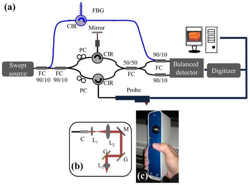
In this study, an SS-OCT system with three-dimensional imaging capability was implemented to monitor wound healing after fractional laser treatments, as shown in Fig. 1(a) . A commercial swept source (HSL-2000, Santec) was used as the light source, providing a broadband scanning range of 110 nm with a center wavelength of 1310 nm. The swept source can provide an output power of 6 mW, and only 2 mW of output power was incident on the skin. To reduce the asynchrony between the interference spectrum and the A-scan trigger, 10% of the output power of the light source was connected to a narrowband fiber Bragg grating (FBG) to generate an A-scan trigger for each A-scan [36]. The used FBG had a Bragg wavelength at 1270 nm, and then, the reflected signal from the FBG was combined with the OCT interference spectrum by a 10/90 fiber coupler. In contrast, 90% of the output power from the swept source was connected to a Mach-Zehnder interferometer, and a hand-held probe composed of two-axis galvanometer was used as a scanning unit in the sample arm. Figures 1(b) and 1(c) show the layout and a picture of the probe. The probe consists of a beam expander, a two-axis galvanometer, and an achromatic lens. When skin is scanned with our OCT system, the skin directly contacts the probe, fixing the focal point at an approximate depth of 300 μm beneath the skin surface. Finally, the interference and A-trigger signals were detected by a balanced detector (PDB150C, Thorlabs). The OCT system can achieve a frame rate of 50 frames/s, where each frame consists of 600 A-scans. In addition, it takes 4 seconds to acquire a three-dimensional image composed of 600 × 200 × 600 voxels, corresponding to a physical image size of 1.5 × 1.5 × 2 mm3.
Fig. 1.
(a) Schematic diagram of the portable SS-OCT system used for monitoring wound healing. (b) Layout of the handheld probe for skin scanning. (c) Picture of the handheld probe. PC: polarization controller, CIR: optical circulator, FBG: fiber Bragg grating, FC: fiber coupler, DAQ: data acquisition board, C: collimator, L1, L2, L3: lenses, M: mirror, and G: galvanometer.
To investigate both the photothermolysis induced by NAFLs and AFLs and the wound healing process, the facial and belly skins of volunteers were exposed to a fractional erbium-doped fiber laser (SR 1500, Fraxel) lasing at 1550 nm as the NAFL or to a fractional carbon-dioxide laser (UltraPulse CO2, Lumenis) centered at 10600 nm as the AFL. After laser exposures, the skins were scanned with the OCT system to differentiate the photothermolysis induced by NAFLs and AFLs, based on the analysis of backscattered intensities and morphological changes. To futher investigate the wound healing process of skin, the exposed regions were scanned using the OCT system at different time points. In the experimental setup, the incident spot sizes of the AFL and NAFL were approximately 120 and 140 μm, respectively. Both the NAFL and AFL produce an approximate exposure area of 1 × 1 cm2 for every exposure. In this study, 3 volunteers were treated with NAFLs on the belly or facial skin, and 4 volunteers were treated with AFLs on the belly or facial skin. All of them were scanned with our OCT system after laser exposures. This study was approved by the Chang Gung Medical Foundation Institutional Review Board (No. 101-2921A3).
3. OCT scanning results
3.1 Phantom experiment
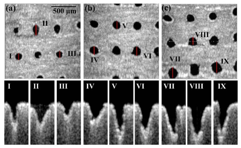
Before investigating the fractional photothermolysis in human skin, the phantom made by gelatin was used as the sample to simulate the soft tissue and was exposed to the AFL. Figure 2 shows the en-face and 2D OCT scanning results for the phantom exposed to various exposure energies (15, 20 and 25 mJ). In the en-face OCT images (Figs. 2(a), 2(b), and 2(c)), the dark spots represent the areas of MTZs at a depth of 250 μm beneath the phantom surface; these spots were due to the volatilization induced by the AFL. The en-face results showed that the shapes and areas of the MTZs induced by the same exposure energy were not identical. Moreover, the B-scan results of locations I-IX, indicated by the red lines in Figs. 2(a)-2(c), are shown in the lower figures of Fig. 2. From the 2D OCT images, one can see that the shapes, the areas and the penetration depths of the MTZs are different, even exposed by the same exposure energy. The difference results from the fact that the penetration depth, shape, and damaged area of the induced MTZ vary, based on several parameters, such as the optical properties of the sample, the water concentration of the sample, the incident angle of the optical beam, and the exposure energy. These variations increase the importance of in vivo and real-time observations for monitoring treatment outcomes and the wound healing process.
Fig. 2.
OCT images of the phantom exposed to various AFL exposure energies. (a), (b), and (c) represent en-face images at the depth of 250 μm beneath the phantom surface for exposure energies of 15, 20 and 25 mJ, respectively. (I)-(IX): B-mode results of locations I-XI indicated by the red lines in (a), (b), and (c).
3.2 Scanning results of human skin
To determine the difference in the photothermolysis induced by NAFLs and AFLs, the belly and facial skins of the different volunteers were exposed to the NAFL and the AFL. The exposure energies of NAFL and AFL were set to be 25 mJ. The exposure densities of NAFLs and AFLs were set to be 20%. Here, the exposure density was defined as the percentage of skin occupied by MTZs. Figures 3(a) and 3(b) represent the pictures of belly skin, which were taken after NAFL and AFL exposures. In this study, both the NAFL and AFL can produce an exposure area of 1 × 1 cm2 for every exposure, as indicated by the black arrows in Figs. 3(a) and 3(b). Then, the exposure areas were scanned with our OCT system. Figures 3(c)-3(h) show the in vivo 2D OCT scanning results of facial (Figs. 3(c)-3(e)) and belly skin (Fig. 3(f)-3(h)), which were obtained before (Figs. 3(c) and 3(f)) and after the NAFL (Figs. 3(d) and 3(g)) or AFL exposure (Figs. 3(e) and 3(h)), respectively. In the OCT results for the skin without laser exposures, shown in Figs. 3(c) and 3(f), the epidermal and dermal layers can be clearly identified. The dermal layer shows stronger backscattered intensities than those of the epidermal layer for normal skin. In contrast, the OCT results for the skin after fractional laser exposures show that the exposures to NAFL or AFL caused changes in the backscattering properties of the epidermal and dermal layers and induced strip structures, indicated by the red arrows. Further comparisons of the structural changes induced by NAFLs and AFLs show that the backscattered intensities of MTZs in Figs. 3(d) and 3(g) are stronger than those of Figs. 3(e) and 3(h). This difference was due to the tissue volatilization that was induced by AFL, decreasing the backscattered intensities from the center region of the MTZ. In contrast, the NAFL exposure caused tissue coagulation, enhancing the backscattered intensities in the epidermal layer. However, the NAFL also induced side effects, such as MEND and cleft basement membrane [37]. The NAFL exposure caused the dermal layer damaged without destroying the stratum corneum, resulting in the accumulation of necrotic debris below the stratum corneum to induce a bulged structure below the skin surface, indicated by the white arrows in Figs. 3(d) and 3(g). However, the MEND formation can eliminate the damage in the epidermal layer and facilitate the regeneration of the epidermis by the rapid movement of the surrounding viable keratinocytes. In addition, the cleft basement membrane was due to the exposure of high laser energy, which can be found in Fig. 3(d) as a dark hole between the epidermal and dermal layers. From the results, one can see that the difference in the photothermolysis including volatilization and coagulation can be identified with OCT imaging.
Fig. 3.
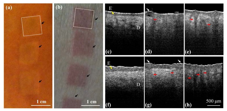
In vivo results of skin before and after NAFL and AFL exposures. (a), (b) pictures of belly skin taken after NAFL and AFL exposures, respectively. The black arrows indicate the exposed areas, and each area equals approximately 1 × 1 cm2. (c), (f) the OCT results of facial and belly skin before laser exposures, respectively. (d), (g) the OCT results of facial and belly skin after NAFL exposures at 25 mJ. (e), (h) the OCT results of facial and belly skin after AFL exposures at 25 mJ. The epidermal layer is indicated by the yellow arrow. The red arrows indicate the structures of the induced MTZs, and the white arrows represent micro-epidermal necrotic debris (MEND). E: epidermis.
3.3 Monitoring of wound healing process after NAFL exposures
To further monitor the progress of wound healing process after NAFL exposures, the treated regions were scanned using the OCT system to acquire 3D images at different time points. To scan the same regions and monitor the progress of wound healing process, the specific exposed areas (1 × 1 cm2), indicated by the dash square in Fig. 3(a), were chosen for OCT imaging at different time points. Because the whole exposed area was not able to be simultaneously scanned with our OCT system, it was not easy to scan the exact region every time. However, as shown in Figs. 3(a) and 3(b), the exposed squares can be identified by the naked eye during the wound healing process. Therefore, the same exposed square can be selected for monitoring the wound healing process. To further reduce the scanning deviation of monitoring regions during wound healing process, a ring mount was fixed on the output end of a handheld probe. The outer diameter of the ring was designed to be 1 cm. Thus, in each measurement, the ring was aligned to the edges of each exposed area (1 × 1 cm2), ensuring the same central region of the exposed square was scanned. Although such measurement may not cover the identical region for observation of wound healing, most of the scanned region is the same in each measurement. Figure 4 illustrates the 2D OCT images of belly skin after the NAFL exposure, obtained on day 0, day 1, day 2, day 3, day 4, and day 6. The resulting stripe structures induced by NAFL can be found in Fig. 4 and gradually disappeared as the recovery time increased. Again, a cleft basement membrane can be found after the NAFL exposure, as shown in Fig. 4(a) and indicated by the white arrow, which was due to the high exposure energy. To determine the wound healing after fractional laser treatment, the wounds were examined by experienced physicians. In a clinic, a wound can be diagnosed to be completely healed by the reepithelialization. However, collagen remodeling can last for 3 months after AFL/NAFL treatments. Therefore, from the OCT results, one can see that the tissue was completely healed on day 6 after the NAFL exposure, as shown in Fig. 4(f).
Fig. 4.
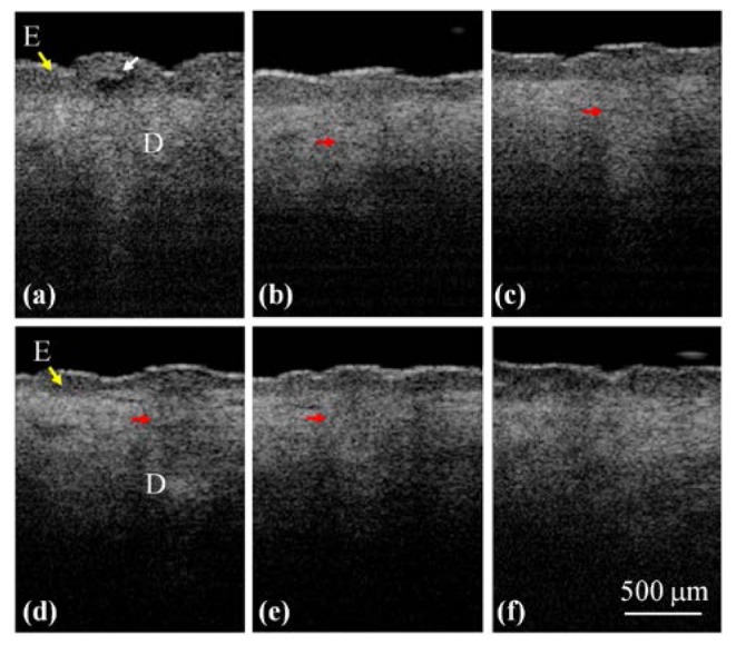
2D OCT images of belly skin after the NAFL exposure, obtained on day 0, day 1, day 2, day 3, day 4, and day 6. The white arrow indicates a cleft membrane induced by the NAFL, and the red arrows show the structures of the induced MTZs.
In addition, because NAFL causes the backscattered intensities of epidermal and dermal layers to be changed, the boundary (basement membrane) of two layers becomes unclear. Hence, the en-face images of the boundary are used to observe the wound healing. The structural changes in the en-face plane can be extracted from the 3D OCT images, and Figs. 5(a) -5(d) show the en-face images obtained on day 0, day 2, day 4, and day 6. The yellow arrows in Fig. 5(a) indicate the cleft basement membrane, and the white arrows represent the damaged spots on the basement membrane that were induced by the NAFL exposure. To further compare the difference before and after the NAFL exposure, the same belly region was scanned using the OCT system before and 1 month after the NAFL treatment. The resulting en-face images from a deeper depth (500 μm below the skin surface, in the dermal layer) are shown in Figs. 5(e) and 5(f), respectively. Before the treatment, the image shows uniform backscattered intensities with small black dots, most likely indicating hair follicles. However, in Fig. 5(f), the spots indicated by the red arrows shows the appearance of tissue scaring even though the tissue had completely healed, which provides evidence for collagen regeneration. Here, the scar refers to the mark due to the laser treatment, and not the crust. Additionally, the area indicated by the lowest red arrow in Fig. 5(f) might be due to the overlapping of adjacent MTZs, resulting in a merged damage area. Finally, it became a larger area of collagen regeneration after wound healing.
Fig. 5.
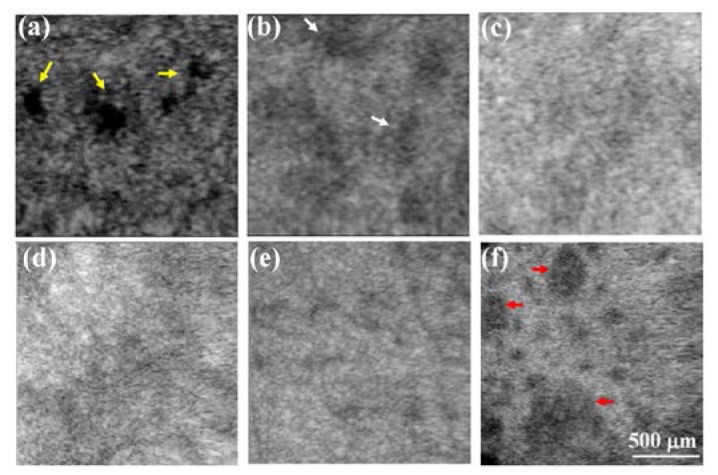
(a)-(d) En-face images of the basement membrane obtained on day 0, day 2, day 4, and day 6. The yellow arrows indicate the cleft basement membrane caused by the exposure to a higher energy of 25 mJ, and the white arrows represent the damaged spots on the basement membrane induced by the NAFL exposure. (e), (f) En-face images at a deeper depth of 500 μm below the skin surface, obtained before and 1 month after the NAFL treatment. The spots indicated by the red arrows show the appearance of tissue scaring even though the tissue had completely healed, providing evidence of collagen regeneration.
3.4 Monitoring of wound healing process after AFL exposures
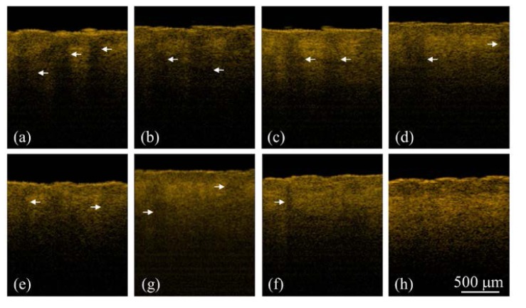
Similarly, to understand the wound healing of skin tissue after AFL treatments, the area indicated by the dash square in Fig. 3(b) was scanned with the OCT system at different time points. As abovementioned, although the region scanned every time was not exactly identical, each scan did cover the same exposed square. Figure 6 shows the 2D OCT images of the belly skin after the AFL exposure, obtained on day 0, day 1, day 2, day 3, day 4, day 6, day 10, and day 14. The white arrows indicate MTZs induced by AFL. As shown in Fig. 6, the stripe structures induced by AFL gradually disappeared with time. In our experiments, the exposed regions after AFL treatments were scanned every day for the following four weeks. Because the OCT results did not show significant differences and MTZ structures cannot be found in OCT images after 2 weeks, the data obtained from day 0, day 1, day 2, day 3, day 4, day 6, day 10, and day 14 were chosen to represent the wound healing process. Further observations of the structural changes during the healing process in the en-face plane are shown in Fig. 7 , which shows the en-face OCT images at two depths of 500 and 750 μm. However, en-face images at various depths can also be obtained for monitoring the wound healing process. The data were recorded on day 0, day 1, day 2, day 3, day 4, day 6, day 10, and day 14. The time-resolved en-face OCT images show that the healing process of the induced MTZs and the diameters of the induced MTZs at the different depths can be estimated. Figure 7 shows that the MTZs induced by AFL can be healed in 2 weeks in contrast to the healing process after NAFL treatments.
Fig. 6.
2D OCT images of belly skin obtained on day 0, day 1, day 2, day 3, day 4, day 6, day 10, and day 14. The white arrows indicate the structures of the induced MTZs.
Fig. 7.
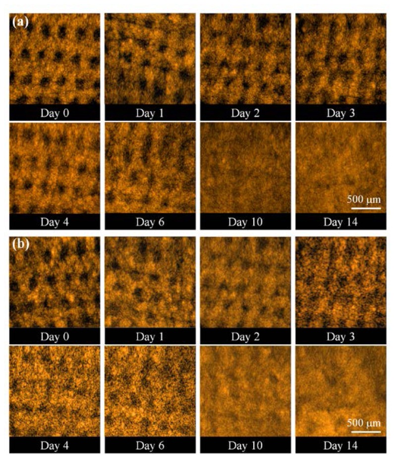
En-face OCT images at two depths: (a) 500 μm and (b) 750 μm. The data were recorded on day 0, day 1, day 2, day 3, day 4, day 6, day 10, and day 14.
4. Quantitative analysis and discussion
To further quantitatively evaluate the wound healing process, an algorithm for evaluating the MTZ area was developed. This algorithm was based on the differentiation of the backscattering properties of the treated and untreated tissues. Figure 8 shows the flow diagram of the OCT image-processing algorithm. First, en-face OCT images at various depths were extracted from 3D OCT images. Next, each en-face image, , was smoothed using a moving averaging approach with a window size of 1515 pixels to acquire the averaged en-face image, . Here, x and y represent the transverse and lateral directions, respectively. Because the backscattered intensity decays as a function of depth, it is difficult to evaluate the damaged areas at various depths while using the same intensity value as a threshold value. Therefore, to differentiate the backscattered intensities of the treated and untreated regions, the mean value of the backscattered intensities over the whole B-scan range (x-direction) in each en-face image was used as a threshold value, . Then, the deviations of the backscattered intensities, , in each en-face image can be expressed as
| (1) |
where i and j represent the ith pixel and jth pixel in the transverse and lateral directions, respectively. Because AFL induces tissue volatilization in the central regions of MTZs, the backscattered intensities in the central regions of MTZs are weaker than those of the surrounding or untreated tissues. Thus, in the central region of MTZs, the values become negative, and the positive values represent stronger backscattered intensities from the surrounding and untreated tissue. Next, the binary images of the induced MTZs, , can be obtained by digitizing using zero value as a threshold value. Finally, the areas of each induced MTZ at various depths can be estimated.
Fig. 8.
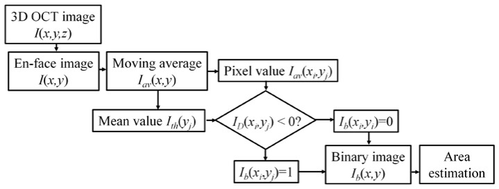
Flow diagram of the OCT imaging process algorithm estimating the MTZ area at various depths.
Figure 9 shows the results of the MTZ areas that were estimated from Fig. 7 using the abovementioned algorithm. Here, from Fig. 7, only complete MTZs were chosen to evaluate an averaged MTZ area for each en-face image. Because the exposed energy decreases as the depth increases, the averaged area of the induced MTZs at the depth of 500 μm was slightly larger than that at the depth of 750 μm on day 0, which can be observed in Fig. 9. In addition, the results also illustrated that the averaged areas of the MTZs decrease as the recovery time increases and that the induced MTZs at deeper depths can eventually recover in two weeks. Here, because the shape, the area and penetration depth of induced MTZs are related to several parameters, such as the water concentration of skin, the optical properties of skin, the incident angle of optical beam, and the incident energy, it causes different damaged areas at the specific depths. Some of the MTZs were still filled with tissue fluid and blood since day 1, making the effective MTZ areas smaller. Also, some MTZs suffered from inflammation, causing the wounds to deteriorate (i.e. the wound size increased). The corresponding measured results hence display the larger standard deviation. Furthermore, in previous reports, the epidermis starts to reepithelialize 72 hours after laser treatment. Therefore, the wound healing of some MTZs again resulted in larger standard deviations after day 4. Thus, it shows large standard deviations of averaged MTZ areas in Fig. 9. Additionally, from the results, the progress of wound healing can be quantitatively evaluated. To further investigate the MTZ areas at different depths, the area ratio of the averaged MTZs area of 750 μm to that of 500 μm was estimated. MTZs induced at deeper depths are smaller than those at shallower depths owing to the decrease in the exposure energy as the depth increases. Therefore, the area ratio is less than one. Figure 10 shows the relationship between the healing time and the area ratio. Here, because the wounds healed on day 14 at both depths, the area ratio of day 14 was not considered in Fig. 10. The result shows that the ratio decreases over time, illustrating the wound healing in the deeper layer is faster than that in the shallower layer. Most importantly, our finding suggests show that wound recovery starts from the deeper tissue, which is also consistent with previous reports [38].
Fig. 9.
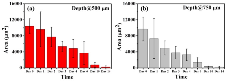
Results of estimating the MTZ areas from Fig. 7. The results indicated that the averaged areas of the MTZs decrease as the recovery time increases and that the MTZs induced at deeper depths can eventually recover in two weeks
Fig. 10.
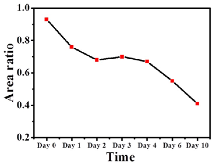
Relationship between the healing time and the area ratio of the averaged MTZs area of 750 μm to that of 500 μm
As compared with the previous report [39], it indicates that the wounds can completely heal in two weeks after AFL exposures. In the stark contrast, the epidermis has already reepithelialized with partial restoration of the basement membrane after 72 hours of NAFL treatment. By 7 days after treatment, the MEND has been exfoliated whereas complete replacement of MTZs with new collagen occurs by 3 months [40]. Consequently, although collagen regeneration can last for three months after NAFL treatment, the epidermis can be reepithelialized in 7 days, which is an indicator to evaluate the wound healing. The wound healing process observed on our OCT results are consistent with those of previous reports. Additionally, we also analyzed the wound healing process after NAFL exposures using the proposed algorithm, but only the result from the en-face plane of the basement membrane exhibits the same trend as the AFL results, which was mainly due to there being no significant change in the backscattered intensity of MTZ, besides the basement membrane. However, in this study, wound healing after NAFL treatments can be directly monitored by the appearance of a basement membrane and the existence of side effects such as MEND. From the results, one can see that OCT can be a clinical methodology for quantitative monitoring of wound healing and outcomes after fractional laser treatments.
5. Conclusions
This study is the first to implement optical coherence tomography to study the photothermolysis induced by NAFLs and AFLs and to quantitatively evaluate the wound healing process after fractional laser exposures. With OCT scanning, the MTZs induced by NAFLs or AFLs can be identified from OCT images. The NAFL exposure causes tissue coagulation, changing the backscattering properties of the epidermal and dermal layers and making it difficult to identify the basement membrane. In contrast, AFL induces tissue volatilization in the central region of MTZs and tissue coagulation in the surrounding tissue; these changes result in the much weaker backscattered intensities in the center of the MTZs. To monitor the progress of the wound healing process after fractional laser treatments, an OCT system was used to scan the treated region at various time points. The OCT results show that the NAFL-induced MTZs can be completely healed in 6 days. In contrast, wound recovery after the AFL exposure takes 2 weeks. Moreover, in this study, we propose a new approach for quantitative evaluation of MTZ areas at various depths. The results show that the areas of the MTZs induced at deeper depths are smaller than those at shallower depths due to the decrease in the exposure energy as the depth increases. Additionally, the quantitative results also provide evidence that wound recovery starts from the deeper region. Finally, the results show that the wound can be healed in 2 weeks after AFL treatments. In conclusion, this study establishes the feasibility of OCT to quantitatively monitor wound healing and outcomes in clinical settings after fractional laser treatments.
Acknowledgment
This research was supported by the National Science Council (NSC), and Chang Gung Memorial Hospital, Taiwan, The Republic of China, under the NSC 101-2221-E-182-056-MY2, NSC 102-2221-E-182-061-MY2 and CMRPD2B0031 grants.
References and links
- 1.Alster T. S., Garg S., “Treatment of facial rhytides with a high-energy pulsed carbon dioxide laser,” Plast. Reconstr. Surg. 98(5), 791–794 (1996). 10.1097/00006534-199610000-00005 [DOI] [PubMed] [Google Scholar]
- 2.Zachary C. B., “Modulating the Er:YAG laser,” Lasers Surg. Med. 26(2), 223–226 (2000). [DOI] [PubMed] [Google Scholar]
- 3.Ross E. V., Sajben F. P., Hsia J., Barnette D., Miller C. H., McKinlay J. R., “Nonablative skin remodeling: selective dermal heating with a mid-infrared laser and contact cooling combination,” Lasers Surg. Med. 26(2), 186–195 (2000). [DOI] [PubMed] [Google Scholar]
- 4.Manstein D., Herron G. S., Sink R. K., Tanner H., Anderson R. R., “Fractional photothermolysis: A new concept for cutaneous remodeling using microscopic patterns of thermal injury,” Lasers Surg. Med. 34(5), 426–438 (2004). 10.1002/lsm.20048 [DOI] [PubMed] [Google Scholar]
- 5.Laubach H. J., Tannous Z., Anderson R. R., Manstein D., “Skin responses to fractional photothermolysis,” Lasers Surg. Med. 38(2), 142–149 (2006). 10.1002/lsm.20254 [DOI] [PubMed] [Google Scholar]
- 6.Hantash B. M., Bedi V. P., Chan K. F., Zachary C. B., “Ex vivo histological characterization of a novel ablative fractional resurfacing device,” Lasers Surg. Med. 39(2), 87–95 (2007). 10.1002/lsm.20405 [DOI] [PubMed] [Google Scholar]
- 7.Freitas A. Z., Freschi L. R., Samad R. E., Zezell D. M., Gouw-Soares S. C., Vieira N. D., Jr, “Determination of ablation threshold for composite resins and amalgam irradiated with femtosecond laser pulses,” Laser Phys. Lett. 7(3), 236–241 (2010). 10.1002/lapl.200910133 [DOI] [Google Scholar]
- 8.Wang C. C., Huang C. L., Lee S. C., Sue Y. M., Leu F. J., “Treatment of cosmetic tattoos with nonablative fractional laser in an animal model: A novel method with histopathologic evidence,” Lasers Surg. Med. 45(2), 116–122 (2013). 10.1002/lsm.22086 [DOI] [PubMed] [Google Scholar]
- 9.Prabhu V., Rao S. B. S., Chandra S., Kumar P., Rao L., Guddattu V., Satyamoorthy K., Mahato K. K., “Spectroscopic and histological evaluation of wound healing progression following Low Level Laser Therapy (LLLT),” J Biophotonics 5(2), 168–184 (2012). 10.1002/jbio.201100089 [DOI] [PubMed] [Google Scholar]
- 10.Pan C. P., Shi Y. H., Amin K., Greenberg C. S., Haroon Z., Faris G. W., “Wound healing monitoring using near infrared fluorescent fibrinogen,” Biomed. Opt. Express 1(1), 285–294 (2010), http://www.opticsinfobase.org/boe/abstract.cfm?uri=boe-1-1-285 10.1364/BOE.1.000285 [DOI] [PMC free article] [PubMed] [Google Scholar]
- 11.Stumpp O. F., Bedi V. P., Wyatt D., Lac D., Rahman Z., Chan K. F., “In vivo confocal imaging of epidermal cell migration and dermal changes post nonablative fractional resurfacing: study of the wound healing process with corroborated histopathologic evidence,” J. Biomed. Opt. 14(2), 024018 (2009). 10.1117/1.3103316 [DOI] [PubMed] [Google Scholar]
- 12.Longo C., Galimberti M., De Pace B., Pellacani G., Bencini P. L., “Laser skin rejuvenation: epidermal changes and collagen remodeling evaluated by in vivo confocal microscopy,” Lasers Med. Sci. 28(3), 769–776 (2013). 10.1007/s10103-012-1145-9 [DOI] [PubMed] [Google Scholar]
- 13.Lange-Asschenfeldt S., Bob A., Terhorst D., Ulrich M., Fluhr J., Mendez G., Roewert-Huber H. J., Stockfleth E., Lange-Asschenfeldt B., “Applicability of confocal laser scanning microscopy for evaluation and monitoring of cutaneous wound healing,” J. Biomed. Opt. 17(7), 076016 (2012). 10.1117/1.JBO.17.7.076016 [DOI] [PubMed] [Google Scholar]
- 14.Sattler E. C., Poloczek K., Kästle R., Welzel J., “Confocal laser scanning microscopy and optical coherence tomography for the evaluation of the kinetics and quantification of wound healing after fractional laser therapy,” J. Am. Acad. Dermatol. 69(4), e165–e173 (2013). 10.1016/j.jaad.2013.04.052 [DOI] [PubMed] [Google Scholar]
- 15.Deka G., Wu W. W., Kao F. J., “ In vivo wound healing diagnosis with second harmonic and fluorescence lifetime imaging,” J. Biomed. Opt. 18(6), 061222 (2013). 10.1117/1.JBO.18.6.061222 [DOI] [PubMed] [Google Scholar]
- 16.Cobb M. J., Chen Y. C., Underwood R. A., Usui M. L., Olerud J., Li X. D., “Noninvasive assessment of cutaneous wound healing using ultrahigh-resolution optical coherence tomography,” J. Biomed. Opt. 11(6), 064002 (2006). 10.1117/1.2388152 [DOI] [PubMed] [Google Scholar]
- 17.Jung W. G., Kao B., Kelly K. M., Liaw L. H. L., Nelson J. S., Chen Z. P., “Optical coherence tomography for in vitro monitoring of wound healing after laser irradiation,” IEEE J. Sel. Top. Quantum Electron. 9(2), 222–226 (2003). 10.1109/JSTQE.2003.812511 [DOI] [Google Scholar]
- 18.Barui A., Banerjee P., Patra R., Das R. K., Dhara S., Dutta P. K., Chatterjee J., “Swept-source optical coherence tomography of lower limb wound healing with histopathological correlation,” J. Biomed. Opt. 16(2), 026010 (2011). 10.1117/1.3535593 [DOI] [PubMed] [Google Scholar]
- 19.Huang D., Swanson E. A., Lin C. P., Schuman J. S., Stinson W. G., Chang W., Hee M. R., Flotte T., Gregory K., Puliafito C. A., Fujimoto J. G., “Optical coherence tomography,” Science 254(5035), 1178–1181 (1991). 10.1126/science.1957169 [DOI] [PMC free article] [PubMed] [Google Scholar]
- 20.Adler D. C., Chen Y., Huber R., Schmitt J., Connolly J., Fujimoto J. G., “Three-dimensional endomicroscopy using optical coherence tomography,” Nat. Photonics 1(12), 709–716 (2007). 10.1038/nphoton.2007.228 [DOI] [Google Scholar]
- 21.Yun S. H., Tearney G. J., Bouma B. E., Park B. H., de Boer J. F., “High-speed spectral-domain optical coherence tomography at 1.3 mum wavelength,” Opt. Express 11(26), 3598–3604 (2003). 10.1364/OE.11.003598 [DOI] [PMC free article] [PubMed] [Google Scholar]
- 22.Wojtkowski M., Srinivasan V., Ko T. H., Fujimoto J. G., Kowalczyk A., Duker J. S., “Ultrahigh-resolution, high-speed, Fourier domain optical coherence tomography and methods for dispersion compensation,” Opt. Express 12(11), 2404–2422 (2004), http://www.opticsinfobase.org/oe/abstract.cfm?uri=oe-12-11-2404 10.1364/OPEX.12.002404 [DOI] [PubMed] [Google Scholar]
- 23.An L., Li P., Shen T. T., Wang R. K., “High speed spectral domain optical coherence tomography for retinal imaging at 500,000 A‑lines per second,” Biomed. Opt. Express 2(10), 2770–2783 (2011), http://www.opticsinfobase.org/boe/abstract.cfm?URI=boe-2-10-2770&origin=search 10.1364/BOE.2.002770 [DOI] [PMC free article] [PubMed] [Google Scholar]
- 24.Yasuno Y., Hong Y. J., Makita S., Yamanari M., Akiba M., Miura M., Yatagai T., “In vivo high-contrast imaging of deep posterior eye by 1- um swept source optical coherence tomography and scattering optical coherence angiography,” Opt. Express 15(10), 6121–6139 (2007), http://www.opticsinfobase.org/oe/abstract.cfm?uri=oe-15-10-6121 10.1364/OE.15.006121 [DOI] [PubMed] [Google Scholar]
- 25.Tsai M. T., Lee H. C., Lee C. K., Yu C. H., Chen H. M., Chiang C. P., Chang C. C., Wang Y. M., Yang C. C., “Effective indicators for diagnosis of oral cancer using optical coherence tomography,” Opt. Express 16(20), 15847–15862 (2008), http://www.opticsinfobase.org/oe/abstract.cfm?uri=oe-16-20-15847 10.1364/OE.16.015847 [DOI] [PubMed] [Google Scholar]
- 26.Tsai M. T., Chang F. Y., Lee C. K., Chi T. T., Yang K. M., Lin L. Y., Wu J. T., Yang C. C., “Observations of cardiac beating behaviors of wild-type and mutant Drosophilae with optical coherence tomography,” J Biophotonics 4(9), 610–618 (2011). [DOI] [PubMed] [Google Scholar]
- 27.Iftimia N., Ferguson R. D., Mujat M., Patel A. H., Zhang E. Z., Fox W., Rajadhyaksha M., “Combined reflectance confocal microscopy/optical coherence tomography imaging for skin burn assessment,” Biomed. Opt. Express 4(5), 680–695 (2013). 10.1364/BOE.4.000680 [DOI] [PMC free article] [PubMed] [Google Scholar]
- 28.Alex A., Weingast J., Weinigel M., Kellner-Höfer M., Nemecek R., Binder M., Pehamberger H., König K., Drexler W., “Three-dimensional multiphoton/optical coherence tomography for diagnostic applications in dermatology,” J Biophotonics 6(4), 352–362 (2013). 10.1002/jbio.201200085 [DOI] [PubMed] [Google Scholar]
- 29.Liu G. J., Jia W. C., Sun V. T., Choi B., Chen Z. P., “High-resolution imaging of microvasculature in human skin in-vivo with optical coherence tomography,” Opt. Express 20(7), 7694–7705 (2012), http://www.opticsinfobase.org/oe/abstract.cfm?URI=oe-20-7-7694&origin=search 10.1364/OE.20.007694 [DOI] [PMC free article] [PubMed] [Google Scholar]
- 30.Sakai S., Yamanari M., Lim Y., Nakagawa N., Yasuno Y., “In vivo evaluation of human skin anisotropy by polarization-sensitive optical coherence tomography,” Biomed. Opt. Express 2(9), 2623–2631 (2011). 10.1364/BOE.2.002623 [DOI] [PMC free article] [PubMed] [Google Scholar]
- 31.Korde V. R., Bonnema G. T., Xu W., Krishnamurthy C., Ranger-Moore J., Saboda K., Slayton L. D., Salasche S. J., Warneke J. A., Alberts D. S., Barton J. K., “Using optical coherence tomography to evaluate skin sun damage and precancer,” Lasers Surg. Med. 39(9), 687–695 (2007). 10.1002/lsm.20573 [DOI] [PMC free article] [PubMed] [Google Scholar]
- 32.Srinivas S. M., de Boer J. F., Park H., Keikhanzadeh K., Huang H. E. L., Zhang J., Jung W. Q., Chen Z. P., Nelson J. S., “Determination of burn depth by polarization-sensitive optical coherence tomography,” J. Biomed. Opt. 9(1), 207–212 (2004). 10.1117/1.1629680 [DOI] [PubMed] [Google Scholar]
- 33.Liew Y. M., McLaughlin R. A., Gong P. J., Wood F. M., Sampson D. D., “ In vivo assessment of human burn scars through automated quantification of vascularity using optical coherence tomography,” J. Biomed. Opt. 18(6), 061213 (2013). 10.1117/1.JBO.18.6.061213 [DOI] [PubMed] [Google Scholar]
- 34.Sakai S., Yamanari M., Miyazawa A., Matsumoto M., Nakagawa N., Sugawara T., Kawabata K., Yatagai T., Yasuno Y., “In vivo three-dimensional birefringence analysis shows collagen differences between young and old photo-aged human skin,” J. Invest. Dermatol. 128(7), 1641–1647 (2008). 10.1038/jid.2008.8 [DOI] [PubMed] [Google Scholar]
- 35.Ohmi M., Tanigawa M., Yamada A., Ueda Y., Haruna M., “Dynamic analysis of internal and external mental sweating by optical coherence tomography,” J. Biomed. Opt. 14(1), 014026 (2009). 10.1117/1.3079808 [DOI] [PubMed] [Google Scholar]
- 36.Tsai M. T., Chi T. T., Liu H. L., Chang F. Y., Yang C. H., Lee C. K., Yang C. C., “Microvascular imaging using swept-source optical coherence tomography with single-channel acquisition,” Appl. Phys. Express 4(9), 097001 (2011). 10.1143/APEX.4.097001 [DOI] [Google Scholar]
- 37.Tannous Z., “Fractional resurfacing,” Clin. Dermatol. 25(5), 480–486 (2007). 10.1016/j.clindermatol.2007.05.007 [DOI] [PubMed] [Google Scholar]
- 38.Pereira R. F., Barrias C. C., Granja P. L., Bartolo P. J., “Advanced biofabrication strategies for skin regeneration and repair,” Nanomedicine (Lond) 8(4), 603–621 (2013). 10.2217/nnm.13.50 [DOI] [PubMed] [Google Scholar]
- 39.Grunewald S., Bodendorf M., Llles M., Kendler M., Simon J. C., Paasch U., “In vivo wound healing and dermal matrix remodeling in response to fractional CO2 laser intervention: Clinicopathological correlation in non-facial skin,” Int. J. Hyperthermia 27(8), 811–818 (2011). [DOI] [PubMed] [Google Scholar]
- 40.Hantash B. M., Mahmood M. B., “Fractional photothermolysis: A novel aesthetic laser surgery modality,” Dermatol. Surg. 33(5), 525–534 (2007). 10.1111/j.1524-4725.2007.33110.x [DOI] [PubMed] [Google Scholar]


