Abstract
This study systematically compares the effects of amphiphilic diblock copolymer (di-BCP) on stabilizing hydrophobic drug nanoparticles formed by flash nanoprecipitation (FNP), and provides a guideline on choosing suitable di-BCPs. Four widely used di-BCPs, i.e., polystyrene-block-poly(ethylene glycol) (PS-b-PEG), polycaprolactone-block-poly(ethylene glycol) (PCL-b-PEG), polylactide-block-poly(ethylene glycol) (PLA-b-PEG), and poly(lactic-co-glycolic acid) (PLGA-b-PEG), and β-carotene as a model drug were used. The study showed that PLGA-b-PEG was the most suitable one, whose hydrophobic block was biodegradable and noncrystallizable as well as had relatively high glass transition temperature (Tg) and a right solubility parameter (δ). The molecular weight of PLGA block over the range from 5k to 15k showed an insignificant effect on controlling the particle size. Amorphous drug particles with a high drug loading of over 83 wt% can be achieved. Much remarkable evidence supported the nanoparticles with kinetically frozen and nonequilibrium packing structures of polymer chains rather than either the micelles or micellar nanoparticles with two well segregated polymer blocks. The thermodynamic effects of the drug and BCP on the particle stability, size and structures were discussed by using solubility parameters.
1. Introduction
Nearly 40% of all new candidates of active pharmaceutical ingredients (API) are hydrophobic, making them difficult to be administrated and circulate in the body for clinic evaluations.[1] Nano-carriers with a diameter of 50–400 nm are able to overcome it to carry anticancer agents through a blood stream, and even target tumors by the enhanced permeation and retention (EPR) effect during the vivo circulation. Different kinds of drug carrier systems have been engineered to fulfill these demands, such as micelles, liposomes, polymersomes, and nanoemulsions. Except for nanoparticles (or called as nanosuspensions of particles)[2-4], however, drug loading capacities of these systems are all low (typically < 20 % [5-7]) and limited by the solubility of the drug in the hydrophobic moieties of the surfactant or the excipient polymer [8]. In order to be able to load more drugs, the larger size of the hydrophobic moiety is desired, and the surfactants need a longer time to relax and to reach their thermodynamic equilibrium. Therefore, producing these carriers typically needs a long processing time, typically a few hours to weeks [9-10]. However, nanoparticles are kinetically stable rather than in a thermodynamic equilibrium state.[11-13] The loading capacity is not limited by the solubility, ideally varying up to 100% of pure drugs and depending on different processing. The processing time is also able to be significantly shortened.
Solvent shifting, also called the Ouzo process, is one of the ways to generate the drug nanoparticles, where solvent and anti-solvent are mixed together. The solvent shifts away from the solutes to its miscible antisolvent. While, the antisolvent shifts in. The solutes are supersaturated, and thereafter precipitate out in the liquid mixture. (See Figure 1d) The solid particles thus formed. A novel technique, flash nanoprecipitation (FNP), has been presented in this sense to effectively produce drug nanoparticles with the size below 100 nm.[11-17] In this technique (Figure 1), a highly hydrophobic drug is dissolved along with a block copolymer in a water miscible organic solvent. This solution is injected into a small chamber at a high velocity along with an anti-solvent, typically water. The high injection velocity generates turbulent mixing, causing the hydrophobic drug and polymer to precipitate very rapidly, forming nanometer scale particles. The block copolymer is amphiphilic. Typically a hydrophilic poly(ethylene glycol) (PEG) block is chemically linked to a hydrophobic block. The hydrophobic block precipitates with the drug, arresting particle growth, while the pendant PEG blocks cover or patch the particle surface against aggregation. This process is continuous and can be readily scaled up to a large volume production as well. The promising FNP therefore has been applied to generate either organic drug or inorganic imagining nanoparticles.
Figure 1.
Schematic of confined vortex mixer and vortex mixing to form amphiphilic diblock copolymer-protected nanoparticles (particle structures in 2D view of a cross section); Note: the nanoparticle structure in e does not indicate a real number and size of the clusters and a real evenness of three chemical components, which can vary in specific cases.
So far, amphiphilic block copolymers (BCPs) have been used, either premade [13, 17-19] or in-situ formed by rapid coupling reactions during the mixing [12-13]. Some instability issues of generated nanoparticles also occurred in past studies.[12-13, 20] However, very few papers [13, 21] have studied factors controlling the stability of BCP protected nanoparticles formed by FNP, which indeed is practically critical for manufacturing, storage, and drug therapies. Moreover, to the best of my knowledge, no study has been done to systematically compare the effects of the different amphiphilic BCPs in FNP. In this study, four widely used amphiphilic BCPs (Scheme 1), polystyrene-block-poly(ethylene glycol) (PS-b-PEG), polycaprolactone-block-poly(ethylene glycol) (PCL-b-PEG), polylactide-block-poly(ethylene glycol) (PLA-b-PEG), and poly(lactic-co-glycolic acid) (PLGA-b-PEG), are used to explore effects of the BCPs on the particle formation and stabilities. β-carotene, a precursor of vitamin A and listed in the U.S. National Cancer Institute drug dictionary, was used as a model drug, because it is highly hydrophobic (logP = 15.5, ACD model by ACDLabs). It ensured that the nanoparticles were relatively stable in term of recrystallization and Ostwald ripening. Moreover, the understanding of the physical process of nanoparticle formation by FNP is still very limited since of the small time scale (< ~10 ms) [13, 16, 22] and space scale (1 – ~10 nm) [12-13, 16]. There have been some debates about the structures of a particle formed by FNP. Johnson et al. [17-18] proposed a micellar structure. BCPs arrested the growth of the drug core by a micellization process (or self assembly) and BCP chains were in thermodynamic equilibrium well aligning on the particle surface like a micelle did. Zhu et al. [12-13] proposed a non-equilibrium packing structure of BCP chains, which randomly packed and coprecipitated with drug molecules to form a particle. Some untapped PEG pointed out to form a hydrophilic surface. This study will show evidence supports the nanoparticles with kinetically frozen and nonequilibrium packing structures of the BCP chains, which are neither a micelle nor a micellar particle with two well segregated blocks. The thermodynamic effects of the drug and BCP on the particle stability, size and structures will also be discussed.
Scheme 1.
Structures of a) β-carotene, b1 - 4) amphiphilic diblock copolymers
2. Materials and Experimental
2.1. Materials
β-Carotene (≥ 97 %), triethylamine (TEA; ≥ 99.5%), ε-caprolactone (≥ 99%), octanoic acid (≥ 98%), camphor sulfonic acid (≥ 98%), 1,8-diazabicyclo [5.4.0]undec-7-ene (DBU; ≥ 99%), Tin(II) 2-ethylhexanoate (~ 95%), calcium hydride (CaH2; 95%), phosphorus pentoxide (≥ 98.5%), water (H2O; HPLC grade), methanol (CH3OH; HPLC grade), chloroform (anhydrous; ≥ 99%), dichloromethane (anhydrous; ≥ 99.8%), and tetrahydrofuran (THF; HPLC grade) were purchased from Aldrich. Chloroform was purified by being washed with water and then distilled from phosphorus pentoxide. Dichloromethane was first dried by being passed through an activated alumina column and then distilled from CaH2. Amine terminated PEG (; ; functionality 0.94–0.96; denoted as PEG(5k)-NH2) was purchased from Nektar Therapeutics, Inc.. Acid chloride terminated PS (; ; functionality 0.75; denoted as PS(2k)-COCl) and PS(10k)-b-PEG(5k) were purchased from Polymer Source. (d, l)-Lactide was purchased from Altasorb and used as received; Glycolide was purchased from Altasorb and was purified by recrystallization from THF. Dihydroxy terminated PEG (, denoted as HO–PEG(5k)–OH) and monomethoxy terminated PEG (, denoted as mPEG(5k)-OH) was purchased from Aldrich. mPEG-OH was dried by azeotropic distillation with toluene at atmospheric pressure.
2.2. Polymer Syntheses
The molecular weights of the amphiphilic BCPs are summarized in Table 1. PS(2k)-b-PEG(5k) was synthesized by coupling equal molar PS(2k)-COCl with PEG(5k)-NH2 in THF in the presence of a slight excess of equivalent TEA. The coupling conversion was determined to be > 90% by gel permeation chromatography (GPC). Considering that the PS(2k)-COCl functionality was 0.75, the product included about 70% of PS-b-PEG, 10% of PS, and 20% of PEG.[23]
Table 1.
Characterizations of amphiphilic BCPs
| PS-b-PEG | PCL-b-PEG | PLA-b-PEG | PLGA-b-PEG | |||||
|---|---|---|---|---|---|---|---|---|
| (g·mol−1) | 2k-b-5k | 10k-b-5k | 12k-b-5k | 10k-b-5k | 5k-b-5k | 10k-b-5k | 15k-b-5k | 10k-b-2k |
| 1.30-b-1.05a | 1.05 | 1.19 | 1.05 | 1.06 | 1.08 | 1.13 | 1.46 | |
Purity: 70% of PS(2k)-b-PEG(5k), 10% of PS(2k), and 20% of PEG(5k)
PCL(12k)-b-PEG(5k) ( by GPC) was synthesized by coupling acid chloride terminated PCL (PCL-COCl) with dihydroxy-terminated PEG (HO-PEG(5k)-OH). PCL-COCl was converted from carboxylic acid terminated PCL (PCL-COOH), which was synthesized by initiating ε-caprolactone by octanoic acid with camphor sulfonic acid as a catalyst and then was fractionated into different molecular weight in THF/methanol cosolvent.[24] was determined by NMR.
PLA(10k)-b-PEG(5k) was synthesized by the ring opening polymerization of (d, l)-lactide with mPEG(5k)-OH as the initiator and DBU as the catalyst in chloroform at room temperature. was determined by NMR, and by GPC as 1.05.[25] Since (d, l)-lactide is a racemic mixture, the resultant PLA is amorphous.
PLGA(5k, 10k, 15k)-b-PEG(5k)s were synthesized by the ring opening polymerization of (d, l)-lactide and glycolide with mPEG(5k)-OH as the initiator and DBU as the catalyst in dichloromethane at room temperature.[25] of PLGA(5k, 10k, 15k)-b-PEG(5k)s were determined by NMR, and were determined by GPC as 1.06, 1.08, and 1.13, respectively. PLGA(10k)-b-PEG(2k) was synthesized by the ring opening polymerization of (d, l)-lactide and glycolide with mPEG(2k)-OH as the initiator and Tin(II) 2-ethylhexanoate as the catalyst in bulk at 150 °C. The obtained product was diluted in THF, dialyzed (Spectra/Pro 7 RC, molecular weight cut off (MWCO) of 1000) with CH3OH for two days to remove unreacted monomers, and then concentrated under vacuum. of PLGA(10k)-b-PEG(2k) was determined by NMR, and was determined by GPC as 1.46. All PLGA blocks used in this study comprised 50% of lactic acid and 50% of glycolic acid confirmed by NMR, and were amorphous.
2.3. Particle Preparation
The confined vortex mixer used for FNP process is illustrated in Figure 1 and described by Liu and Zhu et al. [11, 14]. Typically two of the mixer inlets were connected to two gas tight plastic syringes (60 mL, Kendall Monojet) via Teflon tubing, 1.6 mm ID. Each plastic syringe contained 45 mL of water, and was driven by an infusion syringe pump (Harvard Apparatus, model 945). The other two inlets were connected to two gas-tight glass syringes (10 mL, SGE) via Teflon tubing. One of the syringes contained 5 mL of a 1 wt% of β-carotene and 1 wt% of BCP THF solution, the other contained 5 mL of pure THF. The two glass syringes were driven by a second infusion syringe pump (Harvard Apparatus, PHD 2000 programmable). The pumps propel the four streams at high velocity into the small mix chamber, generating high turbulence. Complete dimensions and evaluation of mixing performance using competitive reactions with small molecule were given by Liu et al. [14].
For most experiments, the flow rates were 120 mL/min for each plastic syringe, and 13.3 mL/min for each glass syringes. From these flow rates, a Reynolds number, Re, of 2976 was calculated, using the relation reported by Liu et al. [14] as
| (1) |
Where ρi is the density of the ith component, Qi is the flow rate of the ith component, Di is the diameter of the ith inlet nozzle (1.1 × 10⁻³ m), si is the cross sectional area of the ith inlet nozzle (1.65 × 10⁻⁶ m2 for all nozzles in the mixer used herein), and ηi is the viscosity of the ith component. The two water streams dominate Re, and this study assumes ρi = 1.0 × 10³ kg·m−3 and ηi = 8.9 × 10⁻⁴ Pa·s at room temperature. The mean Re for each stream is 744, which has the same definition with the work in Johnson[16] and Zhu[12]'s work. The outlet of the mixer was connected via a Teflon tubing to a beaker, where the nanosuspensions were collected. The total injection time was about 23 s. It should be noted that in Liu[14] and Zhu[11]'s work the diameter of the chamber (6.0 × 10⁻³ m) was used for Di, and the density and viscosity of the mixture in the chamber were used as ρi and ηi. Therefore, 3000 of Re in this study by using Equation 1 corresponds to about 18000 with Liu's calculation[14].
2.4. Characterization
All samples were analyzed in the mixing liquid, water with 10 vol% of THF, and also with 1 wt% of NaCl added to this THF/water solution. Salt was used to test the electrostatic stability of particles; 1 wt% was chosen because it is similar to the ion concentration in body fluids. Particle size and distribution were determined by dynamic light scattering (DLS) using a ZetaPALS (Brookhaven Instruments, diode laser BI-DPSS wavelength of 659 nm, round cuvette). The light intensity correlation function was collected at 25 °C and a scattering angle of 90°. The correlation function is a combination of the diffusion coefficient, DDiff i, of each particle which is converted into the particle diameter, di, with the Stokes-Einstein equation:
| (2) |
where kb is the Boltzmann constant. Correlation functions were downloaded from the ZetaPALS and fit using the regularized positive exponential sum (REPES) model. REPES yields a series of discrete particle diameters to represent the particle size distribution. We have found it more accurate than the cumulant model used in most commercial instruments, especially for bimodal or multimodal samples. The free software, GENDIST from Jakes, was used to solve the REPES algorithm[26], and provided the size in an intensity distribution. The intensity averaged particle size, , is defined as:
| (3) |
where ni is the number of particles with a diameter of di. The mass average diameter, , is more practically useful than the usual intensity average for estimating drug loading and availability. It is defined as:
| (4) |
where mi is the mass of a particle with a diameter di. It should be noted that particle sizes within a 3-fold difference can not be distinguished by our DLS. Thus peaks separated by smaller than 3-fold will be merged and appear as a single broad peak.[13]
span is defined to describe a polydispersity by
| (5) |
where d10, d50, and d90 are diameters at which the cumulative mass of the particles is under 10%, 50%, and 90%, respectively. A uniform sample will have span of zero. Larger span, broader the size distribution.
An electrode (model SR-259) with a square cell was used with the ZetaPALS for zeta potential (ζ) measurements. Smoluchowski's model was used for the samples in 1 wt% of saline, and Huckel's model for the samples without saline.
To test reproducibility of the mixing and subsequent DLS and zeta potential measurements as shown in our previous work[11], four individual runs were performed by mixing 1 wt% of β-carotene THF solution with water at Re of 744. The measurements gave and ζ = –9.2 ± 3.4 mV. Thus systematic errors including mixing and measurement were expected to be within ± 10% for and within ± 4 mV for ζ.[11]
Cryogenic transmission electron microscopy (cryo-TEM) specimens were prepared in a controlled environment vitrification system (CEVS) maintained at 30 °C and 100% relative humidity. They were vitrified in liquid ethane at its freezing point, and transferred into an FEI T12 G2 TEM by a Gatan 626 cryo-holder and its “work-station”. Images of the specimens, kept at about −170 °C, were recorded at 120 kV acceleration voltage by a Gatan US1000 cooled CCD camera.
To prepare samples for scanning electron microscopy (SEM) a glass Pasteur pipette was first filled with a small amount of nanosuspension, and then emptied, leaving minute droplets inside the pipette. These were then aspirated onto a silica wafer that had been washed with HPLC grade THF and water.[11-13] After evaporation of solvent at room temperature, the sample was sputter coated with a 30 Å layer of platinum and imaged with a JEOL 6500 SEM.
X-ray diffraction (XRD) patterns of the particles were collected using a Bruker-AXS micro-diffractometer with a 2.2 kW sealed Cu X-ray source. Wet powder samples of nanoparticles were prepared via centrifugal filtration (YM-100, Microcon with a membrane cut-off of 100 kDa equivalent to 8 nm pore size), and measured within 4 hours.
3. Results and Discussion
3.1. Turbulent Mixing and FNP
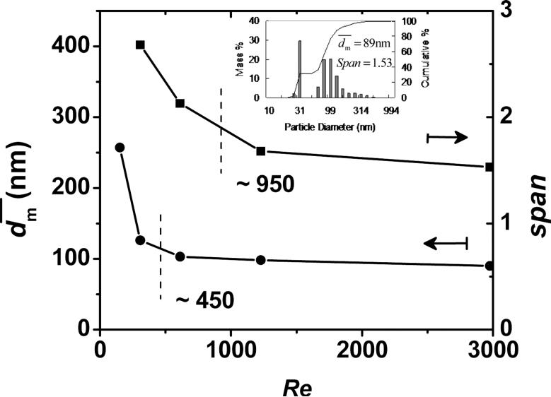
In order to know the flow rate required for producing sufficient mixing, this study measured produced at several Re's. As shown in Figure 2, there is a transition for at Re near 450 (the mean Re = 112 for the single jet), which was also observed in other impingment mixing systems typically at Re between 100–600 for the mean Re for a single jet [16, 27-28]. This transition was considered as a change from a laminar behavior to a more chaotic or turbulent-like behavior,[16] which had been shown by using computer simulations and flow visualization. At a lower limit of Re, H2O phase sheared the β-carotene/THF domains into a much larger characteristic diffusion length, λ, (or Kolmogorov scale length) as shown in Equation 6 and Figure 1c.
| (6) |
The larger diffusion length required a longer time for THF to shift away these domains by molecular diffusion. These domains (or β-carotene particles) therefore stayed deformable with a longer time, providing them more chances to agglomerate back into a larger size. Beyond this transition, as reported by many studies, no further improvement of mixing quality was observed.[16] Johnson et al. attributed this to the insensitivity of the mixing probes, and instead found the mixing quality steadily improved by employing two comparative chemical reactions without phase separation.[16] In this study, at Re greater than ~ 450 (~ 3000 in Reference [11] with Liu's definition of Re [14]), approached an asymptotic value of ~ 90 nm. However, as Re increased, span decreased and the size distribution turned narrower. Re higher than ~ 950 gave a slow decrease of size distribution. It demonstrated that increasing Re had effects on the mixing quality. As expected, further increasing Re reduced λ and thus the time difference to build β-carotene supersaturation between the THF/H2O interface and the middle of the β-carotene/THF domain. The particle generated and grew with a more uniform rate, and therefore the size was narrower. However, was almost independent on Re beyond the transition. The reason may come from that the difference of β-carotene supersaturation between the interface and middle of the β-carotene/THF domain is not significant enough, so as the asymptotic value of is dominantly controlled by the overall supersaturation of β-carotene in the 9H2O/1THF mixture.
Figure 2.
of β-carotene nanoparticles against Re. The insert is the size distribution corresponding to Re of 2976. (Re based on the nozzle diameter and the summation of the four streams)
3.2. Stability of β-carotene Nanoparticles
Three causes can induce the nanoparticle instability, i.e. the 1) aggregation absent of sufficient surface protection such as static and steric stabilizations, 2) Ostwald ripening driven by the solubility difference between different sized particles by the Kelvin equation, and 3) recrystallization from an amorphous to crystalline state to lower lattice energy. Intrinsic properties of either the stabilizer or the hydrophobic compounds affect the nanoparticle stabilities. For this study, the effect from the hydrophobic compounds was fixed. Because 99.999% of the β-carotene (supersaturation S ≈ 105) precipitated based on this concentration [11], the low solubility ensures that the β-carotene nanoparticles are relatively stable in terms of recrystallization and Ostwald ripening, which was also observed by Liu et al. [19]. However, without any stabilizer such as amphiphilic BCPs, they were only stable for few hours [11] by the slightly negative surface charge (ζ ≈ −20 mV; see Tables 2). Based on ζ, it can be estimated that about 0.4 % of β-carotene molecules were charged. The negative surface charge may come from impurities or oxidation.[29] The suspension sedimented on the bottom with the colorless supernatant within one day. When 1 wt% of NaCl was added, it sedimented immediately as well, because the surface charges were neutralized by the salt.
Table 2.
Stability of amphiphilic BCP protected β-carotene nanoparticles in 90 mL of H2O and 10 mL of THF
| β-carotene (mg) | 50 | 50 | 50 | 50 | 50 | |||||
| PS(10k)-b-PEG(5k) (mg) | - | 50 | - | - | - | |||||
| PCL(12k)-b-PEG(5k) (mg) | - | - | 50 | - | - | |||||
| PLA(10k)-b-PEG(5k) (mg) | - | - | - | 50 | - | |||||
| PLGA(10k)-b-PEG(5k) (mg) | - | - | - | - | 50 | |||||
| Saline (1 wt%) | w/o | w/ | w/o | w/ | w/o | w/ | w/o | w/ | w/o | w/ |
| (nm) | 89 | > 1000 | 32 | 36 | 42 | 44 | 38 | 41 | 62 | 69 |
| ζ (mV) | −19.9 | −0.1 | −7.6 | 0.9 | −27.5 | −3.4 | −36.1 | -- | −23.1 | 0.1 |
| Stable (Y/N) | N | N | Y | Y | N | N | N | N | Y | Y |
To obtain stable β-carotene nanoparticles, therefore, it is desired to add a stabilizer, such as amphiphilic BCPs in this study, to inhibit the aggregation. Since the precipitation by FNP is extremely fast, the produced nanoparticles are far away from thermodynamic equilibrium. One of the evidence is that β-carotene without any stabilizer was approved highly amorphous rather than crystalline in our previous work.[11] The larger sized BCPs have longer relaxation times than β-carotene does, and therefore their packing structures more tend to be kinetically frozen than reach at a thermodynamic equilibrium like micelles with well segregated two phases of the blocks. The further evidence about the nonequilibrium structures will be given in the following sections.
3.3. PS-b-PEG
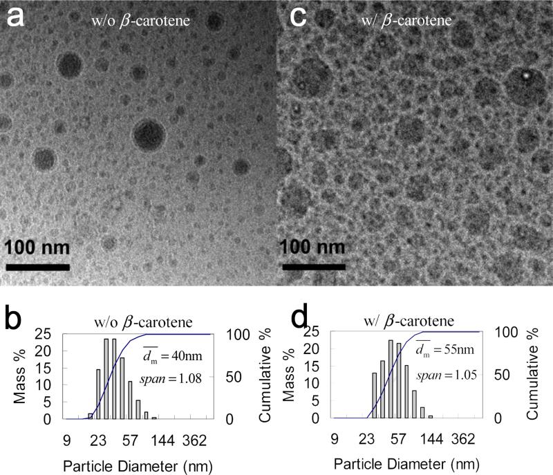
The study started from PS(2k)-b-PEG(5k) as the stabilizer, since it was commercial available. For the control, nanoparticles of PS(2k)-b-PEG(5k) alone without β-carotene were generated by FNP. Based on the molecular weight, the radius of gyration (Rg) of an unperturbed linear chain (the molten state) [30] is estimated to be about 4 nm. If particles were micelles, the diameter should be around 15 nm and the size should be uniform with span of zero. However, was 40 nm and much larger than the one of micelles. This larger size showed that part of the PEG blocks were also inside the core along with PS blocks beside as the corona outside, because PEG and PS chemically bonded to each other. The similar case with a large average size was also observed by Johnson et al. with 28 nm of PS(1k)-b-PEG(3k) nanoparticles, while based on Rg [30] the micelle diameter should be 11 nm. Moreover, the PS(2k)-b-PEG(5k) nanoparticles had span of 1.08 much larger than zero by DLS, showing non-uniformity. From the cryo-TEM image (Figure 3a), the size distribution seemed bimodal. The monomodal size distribution shown by DLS (Figure 3b) was because of the resolution limitation of the DLS technique mentioned in the characterization part. The bimodal distribution was also observed for the β-carotene nanoparticles themselves. The reason is unclear and the big particles may come from the collision and fusion of the small particles during mixing, when THF had not sufficiently shifted away and the small primary particles were still deformable. The larger size and non-uniform distribution showed that the nanoparticles were not a micellar system in a thermodynamic equilibrium. Indeed, the nanoparticles produced by this extremely fast process were kinetically frozen. In the presence of PS(2k)-b-PEG(5k), the β-carotene nanoparticles were stable as well.[23] As shown in Figure 3d, the particles had of 55 nm, which were smaller than the β-carotene nanoparticles without PS(2k)-b-PEG(5k) did (89 nm, Figure 2). The smaller implied that PS(2k)-b-PEG(5k) arrested the growth of the β-carotene nanoparticles, although they had larger than PS(2k)-b-PEG(5k) nanoparticles without β-carotene did (40 nm, Figure 3b). It made sense that β-carotene provided more supersaturation than PS(2k)-b-PEG(5k) alone, and thus increased. From the cryo-TEM image (Figure 3b), nanoparticles showed a bimodal size distribution as well. span by DLS was 1.05. It was smaller than β-carotene nanoparticles without PS(2k)-b-PEG(5k) (i.e., 1.53, Figure 2), however, showed similar value with PS(2k)-b-PEG(5k) nanoparticles without β-carotene (i.e., 1.08, Figure 3b). It seemed that besides Re (Figure 2), Span was more controlled by PS(2k)-b-PEG(5k) rather than the supersaturation of β-carotene.
Figure 3.
Cryo-TEM images and particle size distribution by DLS of PS(2k)-b-PEG(5k) (50 mg) nanoparticles a) and c) w/o β-carotene; b) and d) w/ β-carotene (50 mg) in 90 mL of H2O and 10 mL of THF. (two-stream impingement mixing DLS results converted from Reference[23])
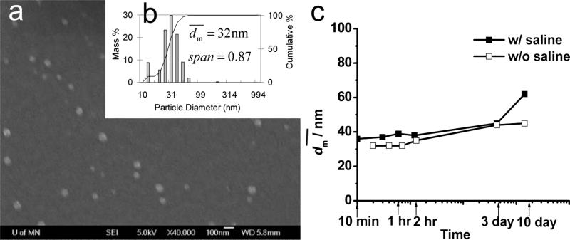
Another molecular weight of PS(10k)-b-PEG(5k) was also used to stabilize β-carotene nanoparticles. As shown in Figure 4, the β-carotene particles have of 32 nm and showed a bimodal distribution with Span of 0.87. The nanoparticles were stable for at least 10 days either without saline or in 1 wt% of saline (Figure 4c). As a control, PS(10k)-b-PEG(5k) nanoparticles without β-carotene was produced by FNP as well. As shown in Table 3, after adding 1 wt% of saline increased from 25 to 30 nm, which was larger than the estimated micelle size. All suggested that the system was not micelles. The size increase must come from the aggregation of the nanoparticles. Part of the surface could be covered by PS rather than PEG, and thus PEG could be partially trapped inside the particle core.
Figure 4.
a) SEM image (scale bar is 100 nm) and b) particle size distribution of PS(10k)-b-PEG(5k) (50 mg) nanoparticles w/ β-carotene (50 mg) by DLS, and c) stability w/ and w/o saline against time in 90 mL of H2O and 10 mL of THF.
Table 3.
Theoretical micelle diameters dmicelle of diblock copolymers and experimental nanoparticle diameters in 90 mL of H2O and 10 mL of THF
| BCP | PS(10k)-b-PEG(5k) | PCL(12k)-b-PEG(5k) | PLA(10k)-b-PEG(5k) | PLGA(10k)-b-PEG(5k) | ||||
| Cal. dmicelle (nm)a | 21b | 19c | 23d, e | --g | ||||
| Saline (1 wt%) | w/o | w/ | w/o | w/ | w/o | w/ | w/o | w/ |
| Exp. (nm) | 25 | 30 | 147 | -- | 20 | --f | 34 | 41 |
| Stable (Y/N) | Y | Y | N | N | Y | N | Y | Y |
Assuming micelles are spherical, although very unlikely with such a block ratio of about 2. Estimated by 4×(Rg, PEG+Rg, hydrophobic block), Rg, PEG(5k) = 2.58 nm based on Reference [30]
Rg, PS(10k) = 2.68 nm in a molten state based on Reference [30]
Rg, PCL(12k) = 2.21 nm in a bulk state based on Reference [35]
Rg, PLA(10k) = 3.23 nm in a bulk state based on Reference [36], 3.09 nm in a molten state based on Reference [37]
Experimental dmicelle =26 nm without saline and 28 nm with 1 wt% of saline in the THF/H2O=1 mixture measured by DLS
DLS showed a peak at 29 nm. But large suspended particles out of the detection limit can be visually observed, which had to be larger than 10 μm
No reference value has been found. But it is expected to be comparable with the value of its analog, PLA(10k)-b-PEG(5k), about 23 nm
3.4. PCL-b-PEG
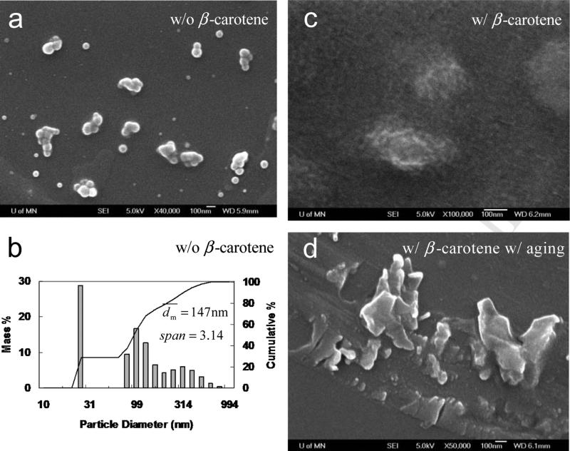
Since PS-b-PEG had a relatively poor biocompatibility, PCL-b-PEG was then employed, which was widely used for drug delivery system and commercial available as well. As a control, PCL(12k)-b-PEG(5k) alone without β-carotene were generated by FNP. Compared with the well-dispersed PS(2k)-b-PEG(5k) nanoparticles (Figure 3a), PCL(12k)-b-PEG(5k) nanoparticles stuck to each other (Figure 5a). DLS showed that was 147 nm and span of 3.14 (Figure 5b). The much larger size and broader size distribution came from the aggregation of the nanoparticles (see Figure 5c). While, in the presence of β-carotene, the particle size decreased to 42 nm (Table 2). Adding salt right after the mixing had very little effect on the particle size. It showed that the β-carotene nanoparticle was sterically stabilized by PCL-b-PEG rather than electrostatically alone without any polymer in Section 3.1.
Figure 5.
SEM images (all scale bars are 100 nm) of PCL(12k)-b-PEG(5k) (50 mg) nanoparticles a) w/o β-carotene right after mixing, c) w/ β-carotene (50 mg) right after mixing, d) w/ β-carotene a few hours after mixing; b) particle size distribution of PCL(12k)-b-PEG(5k) (50 mg) nanoparticles by DLS in 90 mL of H2O and 10 mL of THF.
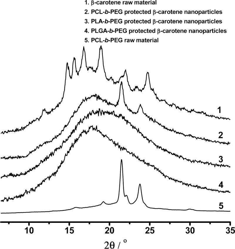
As shown in Figure 5c, many smaller primary particles of 10–20 nm aggregated to form a bigger particles with a loose structures. These primary particles could be the β-carotene nanoparticles whose growth was inhibited by PCL-b-PEG. However, since PCL had Tg of about −60 °C, the primary particles were sticky and thus aggregated. Moreover, the produced nanoparticles were very easy to recrystallize in the 9H2O/1THF mixture, because PCL was crystallizable and deformable (much lower Tg than 100 °C of noncrystallizable PS). Unfortunately, the nanoparticles were only temporarily stable. After a few hours, as shown in Figure 5d, the nanoparticle shape changed from relatively spherical to irregular, suggesting crystallization. And the particles started to sediment. XRD results showed that the crystallization came from PCL rather than β-carotene. (See Figure 10 and Section 3.7) The similar nanoparticle instability in terms of the recrystallization of PCL-b-PEG was observed by Saad [20] as well. In his study, a shishi-kebab morphology (a typical morphology for a semicrystalline polymer) was imaged by TEM but misinterpreted.[20]
Figure 10.
XRD of β-carotene powder (reproduced from Reference [11]) and various BCP protected β-carotene nanoparticles.
3.5. PLA-b-PEG
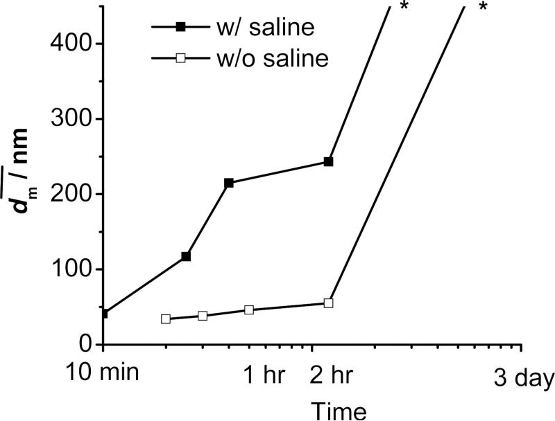
Since PCL-b-PEG protected nanoparticles showed instability due to stickiness with a very low Tg (about −60 °C) and recrystallization, a noncrystallizable polymer block with a high Tg was anticipated to have a good performance to stabilize nanoparticles. A biodegradable and amorphous polymer, PLA (Tg ≈ 34 °C; see Table 4), was thus employed as the hydrophobic block. As anticipated, β-carotene nanoparticles in the presence of PLA-b-PEG did show good dispersity and were fairly spherical (Figure 6c). The nanoparticles were also amorphous (Figure 10, and Section 3.7). However, the nanoparticles were not very stable against the time. (Figure 7) Moreover, if 1 wt% of saline was added, the suspension sedimented in a few hours. All these results indicate that the β-carotene nanoparticles were not sterically stabilized well by PLA-b-PEG.
Table 4.
Tg, and δ of β-carotene and polymer blocks (ΔδPEG = δpolymer - δPEG, and Δδβ= δpolymer - δβ)
Figure 6.
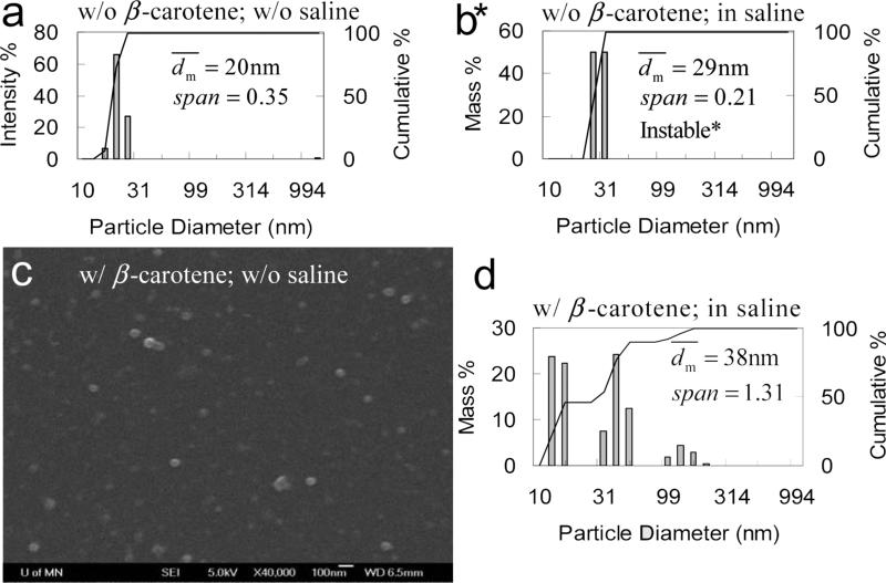
Particle size distribution of PLA(10k)-b-PEG(5k) (50 mg) nanoparticles by DLS a) w/o and b) w/ 1 wt% of saline (*Note: for b, large particles can be observed by naked eyes, which must be larger than 10 um and are out of the detection limit of DLS.) c) SEM image (scale bar is 100nm) of PLA(10k)-b-PEG(5k) (50 mg) nanoparticles with β-carotene (50 mg) w/o saline, and d) particle size distribution by DLS in 90 mL of H2O and 10 mL of THF w/o saline.
Figure 7.
Stability of PLA(10K)-b-PEG(5K) (50 mg) protected β-carotene (50 mg) nanoparticles w/o and w/ saline against time. * Note: Indicative lines at the end. The sample w/ saline sedimented over night, and the one w/o saline sedimented after 2-3 days. No accurate size was able to be obtained with sentiments.
A control experiment with PLA-b-PEG alone was therefore performed. A water clear suspension was obtained. The DLS result (Figure 6a) showed that the nanoparticles had span of 0.35, and of 20 nm which was very comparable with the estimated size of micelles (Table 3). The particles were stable against the time. However, if 1 wt% of saline was added, DLS showed that increased from 20 to 29 nm (Figure 6b). Large suspended particles can be visually observed, which had to be larger than 10 μm. Few hours later, sediments can be observed on the bottom. Since this size range was out of the detection limit of DLS, the peak did not appear in Figure 6b. The real must be larger than 29 nm. The nanoparticles had ζ of −9.4 mV w/o saline and +3.0 mV (a systematic error was ±4 mV; see Section 2.4) in saline. It indicated that PLA-b-PEG nanoparticles were only electrostatically stabilized. Like PLA-b-PEG/β-carotene nanoparticles, the salt neutralized the surface charge and triggered the aggregation of the PLA-b-PEG nanoparticles. As well, the PLA-b-PEG nanoparticles were not sterically stabilized.
It is well known that PLA-b-PEG micelles have been widely employed as a drug delivery system and are stable under a large ionic strength during vivo circulations. In this study, therefore, the second control experiment was performed to compare the stability of the PLA-b-PEG nanoparticles above with PLA-b-PEG micelles, which were made by adding 10 mL of water drop by drop to 10 mL of PLA-b-PEG (5 mg) THF solution overnight with vigorous stirring. The generated micelle system (THF/H2O = 1) was water clear and had of 26 nm (see comparison in Table 3). After adding 1 wt% of saline, no aggregate was visually observed. The system was water clear with of 28 nm and very stable over time. This contrast on stability indicated that the surface of the PLA-b-PEG nanoparticles was not sufficiently covered by PEG like its micelles, and rather was replaced partially by PLA. Not like other nanoparticles, herein too much PEG was trapped inside the core and PLA went outside.
Table 4 gives the solubility parameters of the employed polymer blocks (δpolymer), and from these parameters the difference between each hydrophilic block with PEG is calculated as |ΔδPEG|. A smaller |ΔδPEG| indicates a stronger affinity with PEG.[30-31] During the precipitation, two adjacent BCP chains came closer, in the PS-b-PEG case the PS block with a large |ΔδPEG| had a great preference for PS over PEG. In the PLA-b-PEG case, however, the PLA block with a very small |ΔδPEG| did not have clear preference to either blocks. The affinity of PLA to PEG led that more PEG was trapped by PLA and less the surface was covered by PEG. The nanoparticles were not sterically well protected. More discussions about the thermodynamic effects will be further given in Section 3.8.
3.6. PLGA-b-PEG
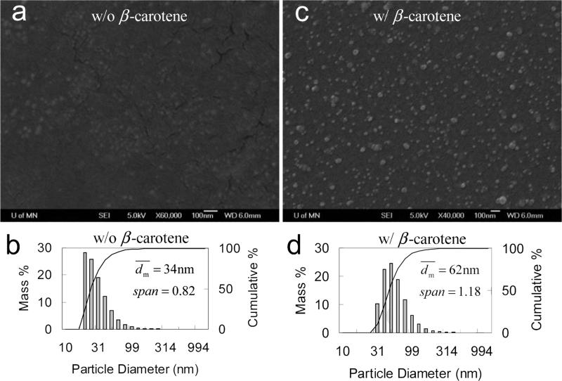
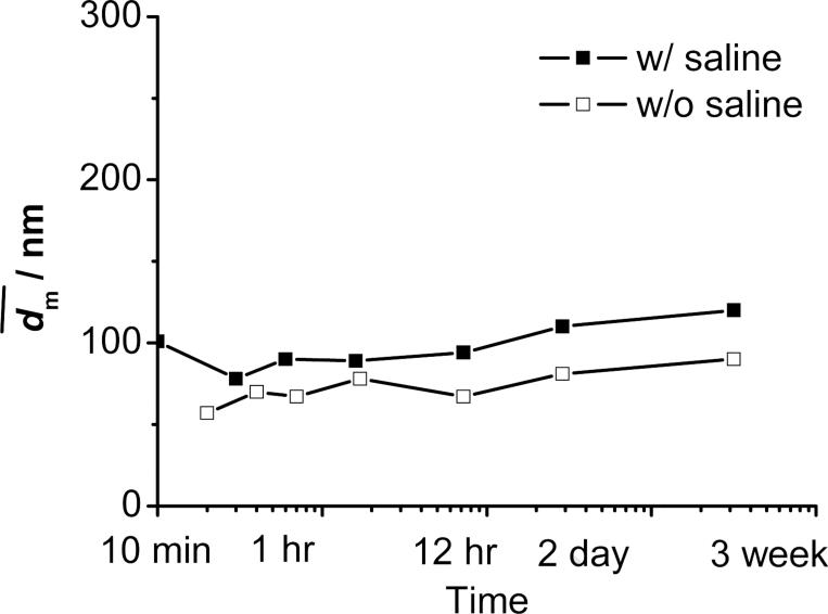
Considering all effects of the BCP investigated above and summarized in Table 5, PLGA-b-PEG was then employed. As anticipated, it showed a good performance to stabilize the β-carotene nanoparticles either without or in 1% saline (Table 6). SEM images in Figure 8 showed that the nanoparticles were fairly spherical and well dispersed. The particles had a non-uniform distribution like those in other cases given by DLS. did not significantly increase for at least 3 weeks either without or in 1 wt% of saline (see Figure 9).
Table 5.
Summary of nanoparticle stability against physical properties of polymers
| Hydrophobic block | PS | PCL | PLA | PLGA |
|---|---|---|---|---|
| Noncrystallizable | + | − | + | + |
| Tg > Troom | + | − | + | + |
| |ΔδPEG| >> 0 | + | + | − | + |
| Stable particle | + | − | − | + |
| Biodegradable | − | − a | + | + |
| US FDA approved for parenteral administration | − | + | + | + |
Biodegradable but in years
Table 6.
and stability of PLGA-b-PEG protected β-carotene nanoparticles against concentration in 90 mL of H2O and 10 mL of THF
| PLGA-b-PEG (mg) | 15k-b-5k | 10k-b-5k | 5k-b-5k | 15k-b-5k | 10k-b-5k | 5k-b-5k | 10k-b-5k | 10k-b-5k | 10k-b-5k | |||||||||
| 50 | 50 | 50 | 50 | 50 | 50 | 10 | 5 | 2.5 | ||||||||||
| β-carotene (mg) | 50 | 50 | 50 | 0 | 0 | 0 | 50 | 50 | 50 | |||||||||
| 1 wt% Saline | w/o | w/ | w/o | w/ | w/o | w/ | w/o | w/ | w/o | w/ | w/o | w/ | w/o | w/ | w/o | w/ | w/o | w/ |
| (nm) | 73 | 70 | 62 | 69 | 62 | 63 | 39 | 45 | 34 | 41 | 43 | 43 | 57 | 75 | 61 | 1012 | 69 | 992 |
| Stable (Y/N) | Y | Y | Y | Y | Y | Y | Y | Y | Y | Y | Y | Y | Y | Y | Y | N | N | N |
Figure 8.
SEM images (all scale bars are 100 nm), and particle size distribution by DLS of PLGA(10k)-b-PEG(5k) (50 mg) nanoparticles a, b) w/o, and c, d) w/ β-carotene (50 mg) in 90 mL of H2O and 10 mL of THF.
Figure 9.
Stability of PLGA(10K)-b-PEG(2K) (50 mg) protected β-carotene (50 mg) nanoparticles w/o and w/ saline against time in 90 mL of H2O and 10 mL of THF.
In order to explore the highest CDL %, defined as , the concentration of PLGA(10k)-b-PEG(5k) was decreased from 50, 10, 5 to 2.5 mg/100 mL for protecting 50 mg/100 mL of β-carotene. As shown in Table 6, 10 mg of PLGA(10k)-b-PEG(5k) was able to sterically stabilize the β-carotene nanoparticles (ζ ≈ 0 mV) in saline, while 5 mg of PLGA(10k)-b-PEG(5k) not able. Because 99.999% of β-carotene precipitated out as the nanoparticles in the 9H2O/1THF mixture,[11] CDL % was at least 50 / (50+10) = 83 wt%.
Liu et al. reported that by FNP can be controlled by altering the solvent/anti-solvent ratio and thus the supersaturation of β-carotene. When less of the organic solvent was used, the supersaturation increased and decreased.[19] In this study, it is necessary to make an attempt to explore the polymer effects on . Since PEG with a molecular weight of 5 kg·mol−1 is able to be excreted from the body as well as provides sufficient hydrophilicity, as shown in Table 6, different molecular weights of PLGA(5k, 10k, 15k)-b-PEG(5k) were employed. In all cases with β-carotene, varied from 60–75 nm and did not show significant change. After adding 1 wt% of saline, barely increased, showing the nanoparticles were well sterically stabilized. As shown in our previous study [14], the solubility of β-carotene (3.1 ng/mL in 9H2O/1THF) was much lower than the ones of BCPs (or critical micelle concentration (CMC) typically 1–1000 μg/mL in H2O [32-33]). Thus, β-carotene has a much higher supersaturation. It made sense that for coprecipitation were very similar in all cases with β-carotene because the total supersaturation was dominantly controlled by β-carotene. Since the solubilities (or CMC) of these BCPs were in a same magnitude, the supersaturation was similar. For cases without β-carotene, as PLGA varied from 5k, 10k to 15k, did not show significant change as well.
3.7. Crystallinity of Nanoparticles
In our previous work [11], β-carotene nanoparticles protected by the water soluble polyelectrolytes by FNP were demonstrated highly amorphous, since THF diffused so rapidly into the water phase that the large β-carotene molecules did not have enough time to align and pack tightly. However, BCPs could be trapped inside the cores rather than only absorb on the particle surface like the polyelectrolytes. In order to verify that β-carotene/BCP interactions do not induce the crystallization of β-carotene, XRD was performed in this study.
As shown in Figure 10, XRD traces did not show any crystalline peak except for the one in the PCL-b-PEG case, where two crystalline peaks came from the crystalline PCL. For PS-b-PEG protected β-carotene nanoparticles, the amorphous nanoparticles were already confirmed in our previous study [12]. Therefore, all these BCP protected nanoparticles were expected to have a higher dissolution rate and bioavailability than their crystalline counterparts.
3.8. Kinetic Formation vs. Thermodynamic Effects
It has been mentioned that the mechanisms of nanoparticle formation by FNP is dominantly a kinetic process which is limited by the time, rather than a dynamic one limited by an overall thermodynamic energy in the micron or larger mixing scale. Much remarkable evidence given above support the nonequilibrium structures of the nanoparticles rather than the micelles, i.e., 1) the non-uniform particle size distribution (Figure 8); 2) larger particle size than the one of equilibrium micelles (Table 3), possible increase of particle size after adding saline (Table 3 and Figure 7), and 4) much higher drug loading capacity up to at least 83 wt% (Section 3.6). It is also not a micellar structure since of above reasons 1-3 when forming BCP particles without β-carotene. However, thermodynamic effects still play some roles for the particle formation, because β-carotene nanoparticles were able to be protected by the PEG corona, and different BCPs did show different performance to stabilize the nanoparticles in terms of (Table 2) and the stability against aggregation (instability in Section 3.5 and Figure 7 for PLA-b-PEG vs. stability in Figure 4 for PS-b-PEG and Figure 9 for PLGA-b-PEG). For this FNP system, there were five components, i.e., β-carotene, hydrophobic blocks, PEG blocks, THF, and H2O. It is better to simplify this complicated system to extract the key interactions to facilitate understanding of the particle formation. For the FNP, the local (<10 nm) precipitation was typically completed within 10 ms[34], the characteristic time should be much shorter than that. This short evolution time determined that only the thermodynamic effects in a very local space were able to play roles for the precipitation. The interactions among molecules which are very close to each other are able to play thermodynamic roles. At the very early stage of the precipitation, β-carotene, hydrophobic blocks, PEG blocks, and THF were in one phase, and THF was shifting to H2O. The dominant interactions during precipitation would be among nearby β-carotene molecules, hydrophobic blocks, and PEG blocks. As shown in Table 2, there was a trend for of BCP protected β-carotene nanoparticles, i.e., PS-b-PEG < PCL-b-PEG ~ PLA-b-PEG < PLGA-b-PEG. This relation was consistent with the trend for the solubility parameter difference between β-carotene and the BCP, |Δδβ|, i.e., PS < PCL < PLA < PLGA with the studied molecular weight (see Table 4). Smaller |Δδβ| illustrated a greater affinity of the hydrophobic block with β-carotene. PS had more preference than PLGA for precipitating together with β-carotene. β-carotene would be surrounded by more PS than PLGA, which chemically bonded with PEG. Therefore, β-carotene nanoparticles ceased the growth earlier and was smaller by using PS-b-PEG than PLGA-b-PEG. It should be noted that PEG has larger |Δδβ| than PLGA. PEG was expected to have greater affinity than PLGA. It implied that more PEG was possibly trapped inside the core of the β-carotene nanoparticles protected by PLGA-b-PEG than by the other BCPs. As well, the nanoparticle surface was expected to have more PLGA than PEG. However, since the Hildebrand solubility parameter theory is not suitable to predict the system with hydrogen bonds, δPEG could change after the hydration of PEG which started close to the end of the precipitation. The situation was more complicated. PLGA-b-PEG could be able to precipitate more layers of itself on the surface, but capable to trap or dissolve drug. PLGA went together with inner PLGA, bringing sufficient chemically linked PEG pointing outside as a corona. A drug rich core/PLGA-b-PEG rich shell/PEG corona structure was able to form. Most recent work showed some evidence of the structure, and the work will be demonstrated in a future paper.
4. Conclusion
In this study, the confined vortex mixer was further evaluated by flash nanoprecipitating β-carotene without amphiphilic BCPs. Mixing with Re higher than ~ 450 gave a sufficient mixing for asymptotic . Further increasing Re still affected the mixing and the particle size distribution narrowed down. Re higher than ~ 950 gave a slow decrease of size distribution.
The effects of the amphiphilic BCPs on the particle stabilities were systematically investigated. The study provided a guideline on choosing the suitable amphiphilic BCP for stabilizing hydrophobic drug nanosuspensions. As summarized in Table 5, PS-b-PEG and biodegradable PLGA-b-PEG showed the best performance to stabilize the β-carotene nanoparticles, since their hydrophobic blocks were noncrystallizable, had relatively high Tg, and large difference of the solubility parameters with PEG. The molecular weight of the PLGA block over the range from 5k to 15k showed an insignificant effect on controlling the particle size.
The high drug loading of over 83 wt% was achieved by using PLGA(10k)-b-PEG(5K). All β-carotene nanoparticles were in amorphous and expected to have a higher dissolution rate and bioavailability. Much remarkable evidence supported the nanoparticles with kinetically frozen and nonequilibrium packing structures of the BCP chains rather than the micelles or micellar nanoparticles with two well segregated phases of the blocks by self assembly. The thermodynamic effects of the drug and BCP on the particle stability, size and structures were discussed by using solubility parameters.
Acknowledgment
This manuscript references Chapter 4 of the dissertation by Dr. Zhengxi Zhu [13]. The author greatly appreciate Dr. Chris Macosko for reviewing the manuscript, and thank Drs. Yutaka Miura, Haitao Qian, Tom Hoye at the Chemistry Department of University of Minnesota for helping provide parts of the polymers [24-25], Dr. Sam Dong for helping take the cryo-TEM images [23], Dr. Bob Prud'homme at the Princeton University for fruitful discussions, for Dr. Timothy Lodge and Dr. Michael Tsapatsis at the University of Minnesota for the access of DLS apparatus. This work was financially supported by the National Science Foundation under the MRSEC Program, Award Number DMR-0212302, IPRIME at the University of Minnesota, and the NIRT Program, Award Number CTS-0506966. Parts of this work were carried out in the Minnesota Characterization Facility, which receives partial support from NSF through the NNIN program.
Footnotes
Publisher's Disclaimer: This is a PDF file of an unedited manuscript that has been accepted for publication. As a service to our customers we are providing this early version of the manuscript. The manuscript will undergo copyediting, typesetting, and review of the resulting proof before it is published in its final citable form. Please note that during the production process errors may be discovered which could affect the content, and all legal disclaimers that apply to the journal pertain.
Reference
- 1.Lipinski CA. Poor aqueous solubility: an industry wide problem in drug discovery. Am Pharm Rev. 2002;5:82–5. [Google Scholar]
- 2.Rabinow BE. Nanosuspensions in drug delivery. Nat Rev Drug Discov. 2004;3:785–96. doi: 10.1038/nrd1494. [DOI] [PubMed] [Google Scholar]
- 3.Patil YB, Toti US, Khdair A, Ma L, Panyam J. Single-step surface functionalization of polymeric nanoparticles for targeted drug delivery. Biomaterials. 2009;30:859–66. doi: 10.1016/j.biomaterials.2008.09.056. [DOI] [PMC free article] [PubMed] [Google Scholar]
- 4.Margulis-Goshen K, Netivi HD, Major DT, Gradzielski M, Raviv U, Magdassi S. Formation of organic nanoparticles from volatile microemulsions. J Colloid Interface Sci. 2010;342:283–92. doi: 10.1016/j.jcis.2009.10.024. [DOI] [PubMed] [Google Scholar]
- 5.Ahmed F, Pakunlu RI, Brannan A, Bates F, Minko T, Discher DE. Biodegradable polymersomes loaded with both paclitaxel and doxorubicin permeate and shrink tumors, inducing apoptosis in proportion to accumulated drug. J Control Release. 2006;116:150–8. doi: 10.1016/j.jconrel.2006.07.012. [DOI] [PubMed] [Google Scholar]
- 6.Ghoroghchian PP, Lin JJ, Brannan AK, Frail PR, Bates FS, Therien MJ, et al. Quantitative membrane loading of polymer vesicles. Soft Matter. 2006;2:973–80. doi: 10.1039/b604212k. [DOI] [PubMed] [Google Scholar]
- 7.Kataoka K, Matsumoto T, Yokoyama M, Okano T, Sakurai Y, Fukushima S, et al. Doxorubicin-loaded poly(ethylene glycol)-poly(beta-benzyl-l-aspartate) copolymer micelles: their pharmaceutical characteristics and biological significance. J Control Release. 2000;64:143–53. doi: 10.1016/s0168-3659(99)00133-9. [DOI] [PubMed] [Google Scholar]
- 8.Kumar V, Prud'Homme RK. Thermodynamic limits on drug loading in nanoparticle cores. J Pharm Sci. 2008;97:4904–14. doi: 10.1002/jps.21342. [DOI] [PubMed] [Google Scholar]
- 9.Bai ZF, Lodge TP. Thermodynamics and mechanism of the block copolymer micelle shuttle between water and an ionic liquid. J Phys Chem B. 2009;113:14151–7. doi: 10.1021/jp907059q. [DOI] [PubMed] [Google Scholar]
- 10.Liu C, Hillmyer MA, Lodge TP. Multicompartment micelles from pH-responsive miktoarm star block terpolymers. Langmuir. 2009;25:13718–25. doi: 10.1021/la900845u. [DOI] [PubMed] [Google Scholar]
- 11.Zhu ZX, Margulis-Goshen K, Magdassi S, Talmon Y, Macosko CW. Polyelectrolyte stabilized drug nanoparticles via flash nanoprecipitation: a model study with beta-carotene. J Pharm Sci. 2010;99:4295–306. doi: 10.1002/jps.22090. [DOI] [PubMed] [Google Scholar]
- 12.Zhu ZX, Anacker JL, Ji SX, Hoye TR, Macosko CW, Prud'homme RK. Formation of block copolymer-protected nanoparticles via reactive impingement mixing. Langmuir. 2007;23:10499–504. doi: 10.1021/la701420z. [DOI] [PubMed] [Google Scholar]
- 13.Zhu ZX. Polymer stabilized nanosuspensions formed via flash nanoprecipitation: nanoparticle formation, formulation, and stability [Ph.D. Dissertation] University of Minnesota; Minneapolis: 2010. [Google Scholar]
- 14.Liu Y, Cheng CY, Prud'homme RK, Fox RO. Mixing in a multi-inlet vortex mixer (MIVM) for flash nano-precipitation. Chem Eng Sci. 2008;63:2829–42. [Google Scholar]
- 15.Liu Y, Fox RO. CFD predictions for chemical processing in a confined impinging-jets reactor. AIChE J. 2006;52:731–44. [Google Scholar]
- 16.Johnson BK, Prud'homme RK. Chemical processing and micromixing in confined impinging jets. AIChE J. 2003;49:2264–82. [Google Scholar]
- 17.Johnson BK, Prud'homme RK. Mechanism for rapid self-assembly of block copolymer nanoparticles. Phys Rev Lett. 2003;91:4. doi: 10.1103/PhysRevLett.91.118302. [DOI] [PubMed] [Google Scholar]
- 18.Johnson BK, Prud'homme RK. Flash nanoprecipitation of organic actives and block copolymers using a confined impinging jets mixer. Aust J Chem. 2003;56:1021–4. [Google Scholar]
- 19.Liu Y, Kathan K, Saad W, Prud'homme RK. Ostwald ripening of beta-carotene nanoparticles. Phys Rev Lett. 2007;98:0361021–4. doi: 10.1103/PhysRevLett.98.036102. [DOI] [PubMed] [Google Scholar]
- 20.Saad WS. Drug nanoparticle formation via flash nanoprecipitation: Conjugation to encapsulate and control the release of paclitaxal. Princeton university; Princeton: 2007. [Google Scholar]
- 21.Kumar V, Wang L, Riebe M, Tung HH, Prud'homme RK. Formulation and stability of itraconazole and odanacatib nanoparticles: governing physical parameters. Mol Pharm. 2009;6:1118–24. doi: 10.1021/mp900002t. [DOI] [PubMed] [Google Scholar]
- 22.Haberkorn H, Franke D, Frechen T, Goesele W, Rieger J. Early stages of particle formation in precipitation reactions - quinacridone and boehmite as generic examples. J Colloid Interface Sci. 2003;259:112–26. doi: 10.1016/s0021-9797(03)00024-9. [DOI] [PubMed] [Google Scholar]
- 23.Anacker JL. Development and use of reactively fromed block copolymer micelles for drug delivery applications [Master Thesis] University of Minnesota; Minneapolis: 2005. [Google Scholar]
- 24.Ji SX, Zhu ZX, Hoye TR, Macosko CW. Maleimide functionalized poly(epsilon-caprolactone)-block-poly(ethylene glycol) (PCL-PEG-MAL): synthesis, nanoparticle formation, and thiol conjugation. Macromol Chem Phys. 2009;210:823–31. doi: 10.1002/macp.200900025. [DOI] [PMC free article] [PubMed] [Google Scholar]
- 25.Qian H, Wohl AR, Crow JT, Macosko CW, Hoye TR. A strategy for control of “random” copolymerization of lactide and glycolide: application to synthesis of PEG-b-PLGA block polymers having narrow dispersity. Macromolecules. 2011;44:7132–40. doi: 10.1021/ma201169z. [DOI] [PMC free article] [PubMed] [Google Scholar]
- 26.Jakes J. Regularized positive exponential sum (REPES) program: a way of inverting laplace transform data obtained by dynamic light scattering. Collect Czechoslov Chem Commun. 1995;60:1781–97. [Google Scholar]
- 27.Kolodziej P, Macosko CW, Ranz WE. The influence of impingement mixing on striation thickness distribution and properties in fast polyurethane polymerization. Polym Eng Sci. 1982;22:388–92. [Google Scholar]
- 28.Malguarnera SC, Suh NP. Liquid injection-molding. 1. investigation of impingement mixing. Polym Eng Sci. 1977;17:111–5. [Google Scholar]
- 29.Mordi RC, Walton JC, Burton GW, Hughes L, Ingold KU, Lindsay DA, et al. Oxidative degradation of beta-carotene and beta-apo-8'-carotenal. Tetrahedron. 1993;49:911–28. [Google Scholar]
- 30.Hiemenz PC, Lodge TP. Polymer chemistry. 2nd ed CRC Press; 2007. [Google Scholar]
- 31.van Krevelen DW. Properties of polymers. 3rd ed. Elsevier Science; New York: 1997. [Google Scholar]
- 32.Allen C, Maysinger D, Eisenberg A. Nano-engineering block copolymer aggregates for drug delivery. Colloids Surf B Biointerfaces. 1999;16:3–27. [Google Scholar]
- 33.Chognot D, Six JL, Leonard M, Bonneaux F, Vigneron C, Dellacherie E. Physicochemical evaluation of PLA nanoparticles stabilized by water-soluble MPEO-PLA block copolymers. J Colloid Interface Sci. 2003;268:441–7. doi: 10.1016/s0021-9797(03)00591-5. [DOI] [PubMed] [Google Scholar]
- 34.Haberkorn H, Franke D, Frechen T, Goesele W, Rieger J. Early stages of particle formation in precipitation reactions - quinacridone and boehmite as generic examples. J Colloid Interface Sci. 2003;259:112–26. doi: 10.1016/s0021-9797(03)00024-9. [DOI] [PubMed] [Google Scholar]
- 35.Qiao CD, Zhao JC, Jiang SC, Ji XL, An LJ, Jiang BZ. Crystalline morphology evolution in PCL thin films. J Polym Sci Pol Phys. 2005;43:1303–9. [Google Scholar]
- 36.Zhang J, Lou JZ, Ilias S, Krishnamachari P, Yan JZ. Thermal properties of poly(lactic acid) fumed silica nanocomposites: experiments and molecular dynamics simulations. Polymer. 2008;49:2381–6. [Google Scholar]
- 37.Dorgan JR, Janzen J, Clayton MP, Hait SB, Knauss DM. Melt rheology of variable L-content poly(lactic acid). J Rheol. 2005;49:607–19. [Google Scholar]
- 38.Törmälä P. Determination of glass transition temperature of poly(ethylene glycol) by spin probe technique. Eur Polym J. 1974;10:519–21. [Google Scholar]
- 39.Toporowski PM, Roovers JEL. Glass transition temperature of low-molecular weight styreneisoprene block copolymers. J Polym Sci Pol Chem. 1976;14:2233–42. [Google Scholar]
- 40.Izuka A, Winter HH, Hashimoto T. Molecular weight dependence of viscoelasticity of polycaprolactone critical gels. Macromolecules. 1992;25:2422–8. [Google Scholar]
- 41.Omelczuk MO, McGinity JW. The influence of polymer glass transition temperature and molecular weight on drug release from tablets containing poly(dl-lactic acid). Pharm Res. 1992;9:26–32. doi: 10.1023/a:1018967424392. [DOI] [PubMed] [Google Scholar]
- 42.Houchin ML, Topp EM. Physical properties of PLGA films during polymer degradation. J Appl Polym Sci. 2009;114:2848–54. [Google Scholar]


