Abstract
In this study, we introduced a novel and convenient approach to culture multiple cells in localized arrays of microfluidic chambers using one-step vacuum actuation. In one device, we integrated 8 individually addressable regions of culture chambers, each only requiring one simple vacuum operation to seed cells lines. Four cell lines were seeded in designated regions in one device via sequential injection with high purity (99.9%-100%) and cultured for long-term. The on-chip simultaneous culture of HuT 78, Ramos, PC-3 and C166-GFP cells for 48 h was demonstrated with viabilities of 92%+/−2%, 94%+/−4%, 96%+/−2% and 97%+/−2%, respectively. The longest culture period for C166-GFP cells in this study was 168 h with a viability of 96%+/−10%. Cell proliferation in each individual side channel can be tracked. Mass transport between the main channel and side channels was achieved through diffusion and studied using fluorescein solution. The main advantage of this device is the capability to perform multiple cell-based assays on the same device for better comparative studies. After treating cells with staurosporine or anti-human CD95 for 16 h, the apoptotic cell percentage of HuT 78, CCRF-CEM, PC-3 and Ramos cells were 36%+/−3%, 24%+/−4%, 12%+/−2%, 18%+/−4% for staurosporine, and 63%+/−2%, 45%+/−1%, 3%+/−3%, 27%+/−12% for anti-human CD95, respectively. With the advantages of enhanced integration, ease of use and fabrication, and flexibility, this device will be suitable for long-term multiple cell monitoring and cell based assays.
Keywords: microfluidics, multiple cell seeding, vacuum actuation, on-chip drug test
1 Introduction
Microfluidics have become an increasingly important platform for biological research in recent years ((Auroux et al. 2002; Salieb-Beugelaar et al. 2010; Kovarik et al. 2012). Cell based analysis especially benefits from the control of small volumes of fluids, low reagent consumption and integration of operations (El-Ali and Jensen 2006). Also, microfluidic systems can be used to study the heterogeneity of cell populations, with precise control over the cell microenvironment.
Cell seeding is the first step for microfluidic cell cultures and assays (Young and Beebe 2010). Multiple cell line seeding is needed for advanced cell system based studies (Hui and Bhatia 2007; Kaji et al. 2010; Taylor et al. 2010). A syringe-controlled cell loading procedure is the most convenient and widely used approach; however, it is difficult to control the loading process and position cells in a specific location on a chip. Gravity flow can be employed to achieve a more uniform cell distribution in some applications (Torisawa et al. 2009, 2010). Pre-fabricated micro structures allow cells to form desired patterns in microfluidic devices, and small traps and grooves have been implemented in microfluidic channels for single cell analysis (Chung et al. 2011). To study cell proliferation, micro curtains have also been fabricated to control the cell seeding region (O’Neill et al. 2009). Although these passive cell seeding approaches provide advantages such as ease of use and high throughput, they are not amenable to all applications. Devices with additional valves or pumps are able to deposit cell populations into separate microchambers and trap individual cell pairs (Lovchik et al.2010; Lee et al. 2005). However, they are characterized by extra complexity in device fabrication and operation.
In this study, we introduced a convenient approach to pattern multiple cells in arrays of microfluidic chambers using one-step vacuum actuation. Vacuum actuation has been applied to microfluidic systems for bubble removal utilizing the gas permeability of poly(dimethylsiloxane) (PDMS) systems (Kang et al. 2008; Skelly and Voldman 2008) and for liquid pumping and handling (Eddings and Gale 2006). In recent work by Kolnik et al., a vacuum actuation line was employed to enable long-term culture of cells in low-shear chambers. In earlier work by our group, low-shear, dead-end channels were used as culture chambers for long-term culture (Liu et al. 2008) and for ischemia-reperfusion injury of primary cardiomyocytes (Khanal et al. 2011). In this work, we created multiple localized cell cultures in low shear microarrays using vacuum actuated cell seeding. Multiple cell lines can be efficiently loaded in individually addressable regions of arrays in one device to achieve better comparative studies. As a proof of concept, four cell lines were simultaneously cultured for long time monitoring on one chip successfully and their individual responses to the apoptosis inducing compounds staurosporine and anti-human CD95 were compared. This device will find use in a variety studies such as cell-cell communication, cell-matrix interactions, high throughput screening of drug action on cells, and a host of other cell-based experiments.
2 Experimental Section
2.1 Instruments and Reagents
RPMI 1640 medium and fetal bovine serum were obtained from Hyclone. Penicillin-streptomycin stabilized solution was purchased from Sigma. SU-8 2015 photoresist and developer were purchased from Micro Chem. Dow Corning Sylgard 184 (PDMS) and curing agent were purchased from Ellesworth Adhesives. Perfluorooctyltrichlorosilane was obtained from Alfa Aesar. Fibronectin, Propidium iodide (PI), Calcein-AM and Mito-Tracker Red were purchased from Invitrogen. Phycoerythrin conjugated anti-human CD19 and anti-human CD95 (APO-1/Fas) were obtained from eBioscience. Phosphate Buffered Saline (PBS, pH 7.4) was purchased from VWR. Annexin V-FITC and Annexin binding buffer were purchased from Southern Biotech. Staurosporine was obtained from Calbiochem.
Fluid flow in this study was controlled by a syringe pump (KD Scientific). Cell monitoring and fluorescence observation were achieved using an inverted epifluorescence microscope (IX71, Olympus) with appropriate filters and a 0.3 NA 10X or 0.1 NA 4X objective. Images of cell seeding and culture were recorded with a cooled CCD camera connected to the microscope and analyzed using ImageJ (Version 1.45s, National Institutes of Health).
2.2 Cells and cell culture
HuT 78 human lymphocytes (ATCC #TIB-161), Ramos human lymphocytes (ATCC #CRL-1596), C166-GFP mouse endothelial (ATCC #CRL-2583), PC-3 prostate cancer (ATCC #CRL-1435), and CCRF-CEM (ATCC #CCL-119) cell lines were obtained from American Type Culture Collection (ATCC). All cell lines were maintained in culture flasks with RPMI 1640 medium supplemented with 10% fetal bovine serum and 20mL/L penicillin-streptomycin stabilized solution. The culture incubator was set at 37°C and 5% CO2. Suspension cell lines were subcultured twice a week, while adherent cell lines were subcultured once they were fully confluent.
2.3 Device fabrication
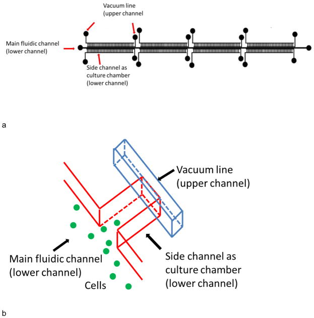
Devices in this work were fabricated using standard multilayer soft lithography procedures (Unger et al. 2000). Briefly, a microfluidic design (Fig. 1a) drawn on computer was printed out as masks by CAD Art Services. The main fluidic channel of the device was 5.5 cm in length and 300 μm in width. 256 culture channels were each 1 mm in length and 150 μm in width and were located on each side of the main channel. The culture channels were divided into 8 regions (4 on each side of main channel) with each region containing 32 channels. The distance between each side channel within one region was ~150 μm. Eight control channels in the top layer were ~1.15 cm in length and 150 μm in width. Each control channel was placed on top of a side-channel region to manipulate them independently. One control (vacuum actuation) channel was located near the end of the culture chamber. A second control channel was fabricated in this mask layer, and was located near the chamber entrance. This control channel near the chamber entrance was used as a debubbler to remove air in channels. Molds for both layers were created on a 4 inch diameter silicon wafer using negative photoresist SU-8 2015. The height of channel features was 38 μm for both layers. The surface of the silicon wafer was protected using perfluorooctyltrichlorosilane prior to replica molding.
Fig. 1.
a) Overview of device design. b) A closeup of the culture wells. The main fluidic channel was 5.5 cm long and 300 μm wide, while side channels were 1 mm long and 150 μm wide. There were 128 repeat side channel units on each side of the main channel. The 256 culture channels were divided into 8 regions of 32 culture channels. 2 control channels were located above the side channels on each region (8 control channels total), on the neck and end of side channels, respectively. The control line on the end was used for vacuum actuation. The line on the neck was used as a debubbler to remove air in channels.
A 10:1 ratio of PDMS pre-polymer and curing agent was employed to make the top layer (control layer). The mixture was baked at 95°C for 1 hour. A 25:1 ratio was used to create the thin fluidic layer. The mixture was first poured onto the silicon wafer and spin coated at 2000 rpm for 30s. After baking at 70°C for 30 min, the bottom layer was attached with top PDMS layer. The two layers were baked at 120°C for 2 hours to form a seal. The resulting PDMS slab was then sealed onto a glass slide using oxygen plasma after punching holes for inlet connections.
2.4 Vacuum-actuated multi-cell seeding operation and on-chip cell culture
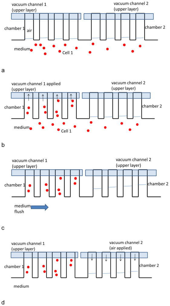
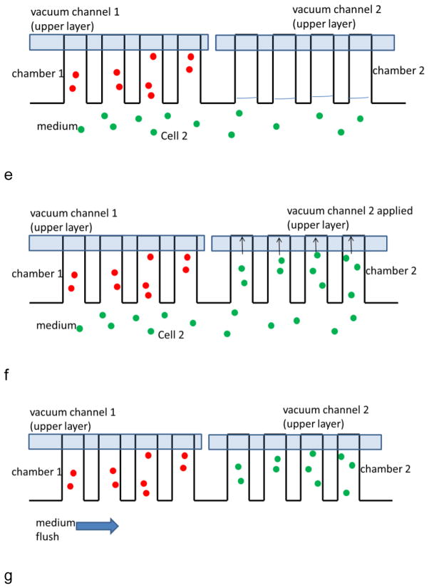
A cell line suspension in RPMI 1640 medium was injected into the main channel (Fig. 2a). Once cell flow stopped, the vacuum line for that section was turned on and air in the side channel was removed rapidly, which leads to the loading of cell suspension (Fig. 2b). The cell line was then rinsed from the main channel with medium (Fig. 2c). During seeding and washing steps, aqueous solutions may be pushed into unseeded side channels. In that case, the air volume in unseeded channels was regenerated by applying positive air pressure (Fig. 2d) from that section’s vacuum line. After washing, a second cell line was injected (Fig. 2e) and seeded into a second section by turning on the corresponding vacuum line (Fig. 2f). And the loading procedure repeated for each subsequent cell line (Fig. 2g).
Fig. 2.
Image of multiple cell seeding procedure. Each image only shows four side channels for clarity. a) Cell 1 suspension was injected into the main channel. b) Once cell flow stopped, the vacuum line 1 was turned on for seeding in chamber region 1. c) Cell 1 region was rinsed from the main channel with medium. d) The air volume in chamber 2 was regenerated by applying positive air pressure. e) After washing, cell line 2 was injected. f) Cell line 2 seeded into chamber 2 by turning on vacuum line 2. g) Cell line 2 was washed by flowing medium. This process was repeated for all eight culture regions.
For on-chip culture, 500 μg/mL fibronectin was coated for surface modification overnight at 4°C and air-dried before each cell culture experiment. RPMI 1640 medium was flown through the main channel at 0.1 mL/h during the entire culture period. The chip was normally maintained in an incubator with 37°C and 5% CO2. Every 24 h, the device was taken out the incubator and cells were observed under a microscope.
2.5 Simultaneous apoptosis induction assays of multiple cell lines
To induce apoptosis, 1 μM of staurosporine was added to RPMI 1640 medium and flowed through the main channel for 16 h at the same rate used for culture (0.1 mL/h). For anti-human CD95 apoptosis assays, 0.8 μg/mL anti-human CD95 was added to RPMI 1640 medium. After 16 h of induction, 400 μL of Annexin binding buffer containing 4 μL of Annexin V–FITC and 8μL of PI was then flowed through the main channel for staining to detect cell apoptosis.
3 Results and Discussion
3.1 Device design and operation
The device fabrication resulted in a thin layer of PDMS between the bottom fluid channel and top air channel. Once vacuum was applied to the control channels, air in the fluid channel was removed rapidly through the thin layer PDMS membrane at the overlapping region of both layers (Fig. 2b). The removal of air led to the filling of aqueous phase.
Although liquid can be filled in side channels easily by vacuum actuation, the introduction of cells and particles is a more complicated process. An increased force is required to move suspended particles into blind channels. This force is determined by the volumetric flow rate and cross section of channels. The volumetric flow rate for cell loading depends on the air removal rate, which is related to the permeability of the PDMS, the thickness of thin layer membrane, and the applied vacuum. Practically, to enhance the air removal rate, the thickness of thin layer membrane must be reduced and the vacuum must be increased. In this study, the PDMS membrane was ~10 μm and the vacuum was ~−70 kPa. The cross sectional area of upper and lower layers is another important factor for cell transportation into the culture chambers. If the cross section area is too large or too small, cell loading may not be achieved. We designed side channel dimensions to be 150 μm in width and 38 μm in height. This design was optimized for cell viability during long-term culture. In other experiments, the channel geometry must be optimized to balance efficient vacuum actuation and the needs of subsequent studies in the chip.
Another concern when incorporating vacuum actuation is the position of the vacuum channel in relation to the lower fluid channel. Vacuum actuation ceases once liquid reaches the thin membrane between the vacuum channel and lower channel. Therefore it is best to place the vacuum channel at the distal end of the microfluidic structure that is to be filled with fluid. In this work, side channels of 1.0 mm length, 150 μm width, and 38 μm height required channel filling times of 30–40 seconds. The filling time using vacuum actuation was not critical in these studies using cell cultures, as the culture duration (48–168 hours) was significantly longer than the filling time. However, in other experiments, where vacuum actuation could be used to wet blind channels for other reactions, the filling time can be adjusted by the applied vacuum.
The vacuum actuation process can also be reversed. If positive air pressure was applied to the vacuum line, then fluid in the lower channel was displaced. This capability allows multiple fluids to be introduced sequentially to the main channel, drawn into blind channels, and then removed to allow additional reagents to be introduced. In this work, this feature enables regenerating air volume for next cell line loading and removing fibronectin solution in the side channels (Fig. 2d). Our vacuum actuation step is similar in implementation to other vacuum actuation strategies(Kolnik et al.). However, in our approach we have created multiple vacuum actuation regions that are individually addressable for cell line loading. The ability to load multiple cell types into the chip in a facile manner allows for the evaluation of target compounds in a variety of cell-based assays.
3.2 Multi cell loading and loading purity characterization
The device is amenable for culturing up to 8 cell lines simultaneously and performing cell-based assays on them. However, in our work, as a proof of concept, we only performed simultaneous monitoring and assays on 4 cell lines. Each cell line occupies two regions cambers that are in opposite positions on the chip. In order to perform multi cell line assays and monitoring on one culture chip, we first established a protocol for multiple cell line seeding. We characterized the loading purity to ensure multiple cell lines seeded in designated regions in one device with little interference. To differentiate the 4 cell types, different fluorescent labels were attached to cell lines for identification at different channels on microscope; C166-GFP cells were stained with Calcein-AM, HuT 78 with Mito-Tracker Red, Ramos with PE-antiCD19, and CCRF-CEM were left unstained respectively (see Supporting Information for white light and fluorescence images). Then the 4 labeled cell lines were seeded into designated regions in one cell culture chip using sequential vacuum actuation, as described in the experimental section (Fig. 3). Fluorescent images were taken to determine the purity of cell seeding and the results are listed in Table 1.
Fig. 3.

Layout of 4 regions of cell arrays after 4 cell line seeding working cycles. Each region only shows four side channels.
Table 1.
Seeding purities of four cell lines at their designated regions.
| Actual Cell Number | C166-GFP | HuT 78 | Ramos | CCRF-CEM |
|---|---|---|---|---|
| Designated Cell Region | ||||
| C166-GFP Region | 1954 | 1 | 2 | 0 |
| HuT 78 Region | 0 | 808 | 0 | 0 |
| Ramos Region | 0 | 0 | 1550 | 0 |
| CCRF-CEM Region | 0 | 0 | 0 | 1149 |
| Purity (%) | 100 | 99.9 | 99.9 | 100 |
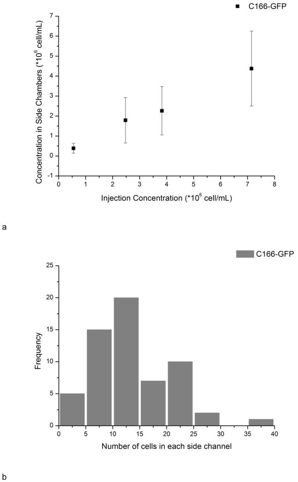
For C166-GFP and CCRF-CEM cells, all the cells were in the correct channels. For HuT 78 and Ramos, only one or two cells went to the incorrect channels out of cell numbers ranging from ~800 to ~2000. The 99.9–100% purity is acceptable for localized cell monitoring. As depicted in Fig. 4a, the cell concentration in side channels was correlated with injection concentration, indicating seeding density can be controlled with different injection concentrations. The cell concentration in side channels was calculated using the cell number in each side channel divided by channel volume (5.7 nL). The average cell concentration in side channels tended to be lower than the hemacytometer concentration, eg, 2300±1200 vs. 3800±400 cells/μL. This difference could be attributed to differences in cell flow under loading conditions, and from losses in the syringe, tubing, and connections between the tubing and chip. There is also a small dead volume at the distal end of each culture chamber, which may also reduce cell or particle loading into longer channels. It should also be noted that the variation of cell density in side channels was due to the non-uniform distribution of cells in the main channel (Fig. 4b). The wide distribution comes from complicated flow profiles when actuating hundreds of side channels simultaneously, and the heterogeneity of cell concentration distributions at the nanoliter scale. In addition, there is a linear pressure drop along the main channel, however for vacuum actuation the syringe pump is switched off and a static fluid and particle suspension is loaded into the culture channels. In future work we will optimize loading conditions and chip geometry for more uniform cell loading. This procedure allows creating multiple cell seeding regions in one device with little interference. More importantly, the cell loading is fast and convenient; the filling time for each vacuum actuation is 30–40 seconds and the whole process can be conducted without the need of complex micro pumps or valves.
Fig. 4.
a) The relationship between injecting concentration and seeding concentration. The concentration of cells in the chambers was calculated from number of cells in each side channel divide by the volume of side channels (5.7 μL) after washing out cells in the main channel. Error bars represent the standard deviation of counting 40–70 side channels. b) Distribution of cell number in each individual side channels. The injection concentration was 3800±400 cells/μL.
3.3 On-chip simultaneous multi cell culture
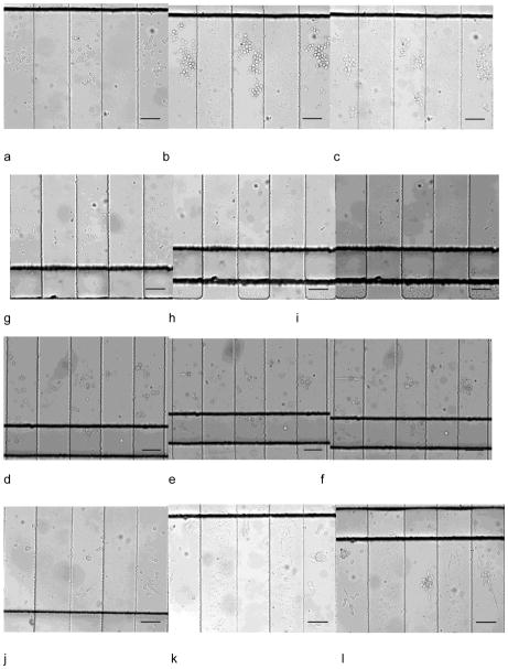
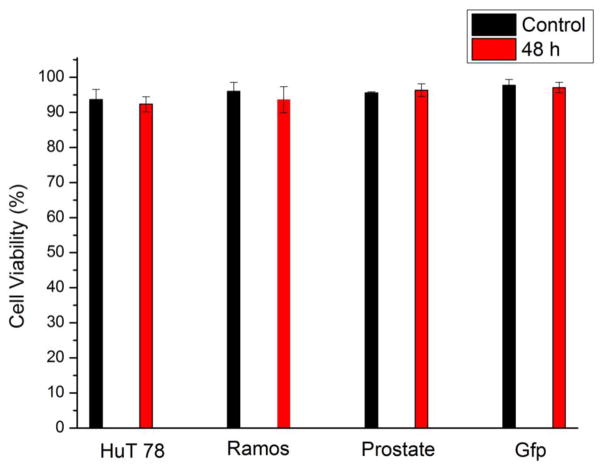
Since multiple cell lines can be seeded in designated regions with little interference, the device can be employed in long-term multiple cell line monitoring. We studied on-chip culture of HuT 78, Ramos, prostate cancer cells (PC-3) and mouse endothelial cells (C166-GFP). After seeding in the side channels, the cell culture region was free of convention, resulting in low shear stress on the cells. Fig. 4a–l showed simultaneous culture of the four cell lines at 1.5 h, 24 h, and after 48 h. C166-GFP and prostate cancer cells are adherent cell line, showing attachment on the surface. The suspension cell line, HuT 78 and Ramos, did not attach on the surface, but they remained in the side channels after 48 hours of 0.1 mL/h continuous flow in the main channel. After 48 h of cell culture, all the tested cell lines maintained high viability that was comparable to the initial viability (Fig. 5). The cell culture experiment was stopped at 48 h but was not limited to this period. C166-GFP cells were cultured for 168 h on the chip with 96% viability, which was the longest period in this study (Supporting Information). In addition to viability, cell proliferation in the chip was also studied. Since cells were cultured in discrete side channels, cell proliferation in each individual side channel is traceable.
Fig. 5.
Simultaneous culture of HuT 78, Ramos, prostate cancer cells and C166-GFP cells in different regions in one device. Culture at 1.5 h, 24 h, 48 h of HuT 78 T (a–c), Ramos (d–f), prostate cancer cells (g–i) and C166-GFP (j–l). Scale bars indicate 100 μm.
The device is tolerant to inadvertent introduction of air bubbles from buffer solutions, since bubbles from the main channel will not enter the side channels where cells are cultured. Moreover, bubbles can be easily removed by activating the vacuum line near the chamber entrance without disrupting fluid flow and cell cultures.
3.4 Mass transport in side channels
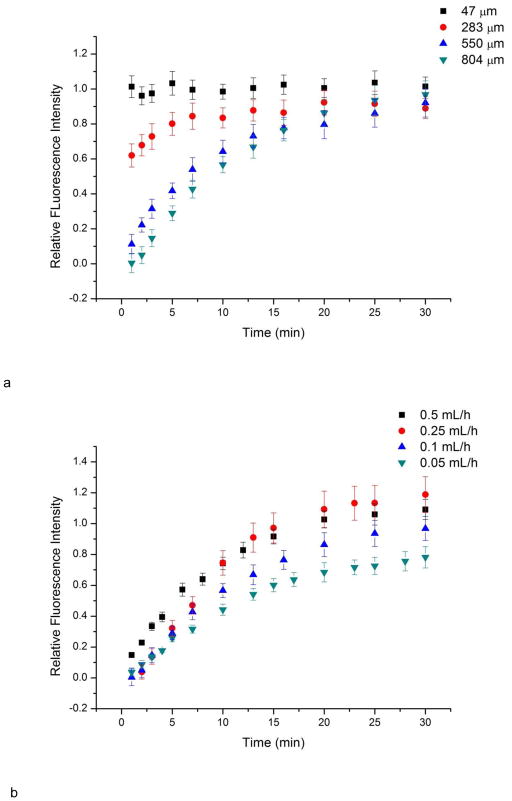
The medium replenishment and waste removal of this device was achieved via continuous flow in the main channel. The T-junction setup has been reported to be able to provide medium exchange for dead-end side channels (Liu et al. 2008; Liu et al. 2009). Mass transport between main channel and side channels was studied using fluorescein solution. Generally, once fluorescein solution was observed in the main channel, side channels started to show fluorescence. The intensity in side channels increased over time, indicating the mass transport of fluorescein between main channel flow and side channels (Fig. 6). The change of intensity in side channels was studied at different locations and at different main channel flow rates. The difference in fluorescence intensity decreases along the culture channel distance as a function of time (Fig. 6a). The relative fluorescence intensity is the ratio of fluorescence intensity at any position to the intensity at the main channel. Mass transport at position 47 μm to the main channel was mainly governed by convection flow as it showed similar fluorescence intensity to the main channel. For the deeper positions, longer transportation time was required to equilibrate, because major mass transport is achieved via diffusion instead of convection flow. This feature prevented excessive shear from main channel flow and formed a low shear cell culture chamber. Meanwhile, the diffusion time is also related to the main channel flow rate (Fig. 6b). This feature can be used to adjust the medium replenishment rate in side channels, which is important for on-chip cell culture (Yu et al. 2007).
Fig. 6.
Viability of HuT 78, Ramos, PC-3 and C166-GFP after 48 h of on-chip culture. Cell viability was determined using 10 μg/mL propidium iodide (PI). Control cell viability is the viability at 0 h. Error bars represent the standard deviation of three individual trials.
3.5 On-chip apoptosis induction
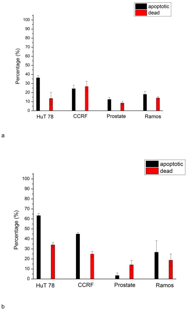
The main advantage of our design is to perform cell based assays on multiple cell lines simultaneously in a single device. Better comparison between cell responses can be achieved, since the variation among different experiments can be decreased. To demonstrate the effectiveness of the device, we conducted drug tests using HuT 78, CCRF-CEM, PC-3, Ramos cells, and compared their individual responses in one chip. Two apoptosis inducers were studied, staurosporine and anti-human CD95. The two drugs initiate apoptosis via two different pathways. Staurosporine triggers the intrinsic pathway (damage response) and anti-human CD95 triggers the extrinsic (death receptor) pathway. After treating cells with staurosporine and anti-human CD95 for 16 h, Annexin V–FITC and PI were employed to verify cell apoptosis and death. After 16h induction by staurosporine, the percentage of apoptotic cells and dead cells of HuT 78, CCRF-CEM, PC-3 and Ramos cells were 36%+/−3%, 24%+/−4%, 12%+/−2%, 18%+/−4% and 14%+/−7%, 278%+/−6%, 8%+/−2%, 14%+/−2%, respectively (Fig. 7). After induction by anti-human CD95, the percentage of apoptotic cells and dead cells of the four cell lines were 63%+/−2%, 45%+/−1%, 3%+/−3%, 27%+/−12% and 34%+/−3%, 25%+/−3%, 14%+/−5%, 19%+/−6%, respectively. In both cases, PC-3 prostate cells were least susceptible to apoptosis induction. The reduced susceptibility of PC-3 cells to staurosporine may result from their higher expression of the Bcl-xL protein when compared with other prostate cell types and the fact that they cannot release cytochrome c to the cytosol (Marcelli et al.2000). The expression of CD95 may be lower in PC-3 cells and will be examined in future work. A direct comparison between the four cell lines was made in a single device under identical conditions. Multiple cells can be seeded through main channel and then tested against stimuli delivered by the same main fluidic channel, without additional pumps and valves needed. A real time read out of assay results by detecting method as a fluorescence microscope can be achieved.
Fig. 7.
Mass transport study using fluorescein solution. a) Fluorescence intensity change over time at different locations in side channels under flow rate 0.1 mL/h. Locations are measured from the inlet of the culture channel. The relative fluorescence intensity is the ratio of fluorescence at certain position to fluorescence at main channel. If the value approaches to 1, it indicates the mass transport of fluorescein. b) Fluorescence intensity change over time 804 μm from the culture channel inlet as a function of main channel flow rate. Slower main channel flow rates le to slower mass transport to the side channels. Error bars represent standard deviation of values from four individual side channels.
Apoptotic and dead cell percentage of HuT 78, CCRF-CEM, PC-3 and Ramos cells after 16 h induction by a) staurosporine and b) anti-human CD95. PC-3 prostate cells are least susceptible to both staurosporine and anti-CD95 antibodies, as shown by the reduced number of apoptotic cells in the culture chambers. Error bars represent standard deviation of three individual trials.
4 Conclusion
In this study, we introduced a novel and convenient approach to culture multiple cell types in localized arrays of microfluidic chambers using one-step vacuum actuation. Multiple cell lines can be efficiently loaded in individually addressable regions of arrays in one device in order to achieve better comparative studies. Simultaneous culture of four cell lines was achieved with high viability. At the same time, individual responses of four cell lines to staurosporine and anti-human CD95 were compared, on the same device. This chip is also suitable for integrated cell based assays, especially for long term, on-chip monitoring. The simplicity in fabrication and operation will make this device easily adopted by other research labs with a basic soft lithography facility. However, optimization of device dimensions and fluid network are still required to further enhance cell loading uniformity and the cell culture microenvironment. Nevertheless. this microdevice can be scaled up to culture large numbers of cell lines for rapid drug testing, comparative cell response, and a host of other cell-based studies.
Supplementary Material
Acknowledgments
Y.G. would like to acknowledge support by a Provost’s Fellowship. This work was supported by grants from the National Institutes of Health (Grants RR025782 and GM103550) and the Robert A. Welch Foundation (Grant D-1667).
References
- Arora A, Simone G, Salieb-Beugelaar GB, Kim JT, Manz A. Anal Chem. 2010;82:4830. doi: 10.1021/ac100969k. [DOI] [PubMed] [Google Scholar]
- Chung K, Rivet CA, Kemp ML, Lu H. Anal Chem. 2011;83:7044. doi: 10.1021/ac2011153. [DOI] [PMC free article] [PubMed] [Google Scholar]
- Eddings MA, Gale BK. J Micromech Microeng. 2006;16:2396. [Google Scholar]
- El-Ali J, Sorger PK, Jensen KF. Nature. 2006;442:403. doi: 10.1038/nature05063. [DOI] [PubMed] [Google Scholar]
- Hui EE, Bhatia SN. PNAS. 2007;104:5722. doi: 10.1073/pnas.0608660104. [DOI] [PMC free article] [PubMed] [Google Scholar]
- Kaji H, Yokoi T, Kawashima T, Nishizawa M. Lab Chip. 2010;10:2374. doi: 10.1039/c004583g. [DOI] [PubMed] [Google Scholar]
- Kang JH, Kim YC, Park JK. Lab Chip. 2008;8:176. doi: 10.1039/b712672g. [DOI] [PubMed] [Google Scholar]
- Khanal G, Chung K, Solis-Wever X, Johnson B, Pappas D. Analyst. 2011;136:3519. doi: 10.1039/c0an00845a. [DOI] [PMC free article] [PubMed] [Google Scholar]
- Kolnik M, Tsimring LS, Hasty J. Lab Chip. 2012;12:4732. doi: 10.1039/c2lc40569e. [DOI] [PMC free article] [PubMed] [Google Scholar]
- Kovarik ML, Gach PC, Ornoff DM, Wang Y, Balowski J, Farrag L, Allbritton NL. Anal Chem. 2010;84:516. doi: 10.1021/ac202611x. [DOI] [PMC free article] [PubMed] [Google Scholar]
- Lee PJ, Hung R, Shaw L, Jan L, Lee P. Appl Phys Lett. 2005;86:223902. [Google Scholar]
- Liu K, Tian Y, Burrows SM, Reif RD, Pappas D. Anal Chim Acta. 2009;651:85. doi: 10.1016/j.aca.2009.08.007. [DOI] [PubMed] [Google Scholar]
- Liu K, Pitchimani R, Dang D, Bayer K, Harrington T, Pappas D. Langmuir. 2008;24:5955. doi: 10.1021/la8003917. [DOI] [PubMed] [Google Scholar]
- Lovchik R, Tonna N, Bianco F, Matteoli M, Delamarche E. Biomed Microdevices. 2010;12:275. doi: 10.1007/s10544-009-9382-9. [DOI] [PubMed] [Google Scholar]
- Marcelli M, Marani M, Li X, Sturgis L, Haidacher SJ, Trial J, Mannucci R, Nicoletti I, Denner L. Prostate. 2000;42:260. doi: 10.1002/(sici)1097-0045(20000301)42:4<260::aid-pros3>3.0.co;2-0. [DOI] [PubMed] [Google Scholar]
- O’Neill AT, Monteiro-Riviere NA, Walker GM. Lab Chip. 2009;9:1756. doi: 10.1039/b819622b. [DOI] [PubMed] [Google Scholar]
- Skelley AM, Voldman J. Lab Chip. 2008;8:1733. doi: 10.1039/b807037g. [DOI] [PubMed] [Google Scholar]
- Salieb-Beugelaar GB, Simone G, Arora A, Philippi A, Manz A. Anal Chem. 2010;82:4848. doi: 10.1021/ac1009707. [DOI] [PubMed] [Google Scholar]
- Taylor AM, Dieterich DC, Ito HT, Kim SA, Schuman EM. Neuron. 2010;66:57. doi: 10.1016/j.neuron.2010.03.022. [DOI] [PMC free article] [PubMed] [Google Scholar]
- Torisawa YS, Mosadegh B, Luker GD, Morell M, O’Shea KS, Takayama S. Integr Biol. 2009;1:649. doi: 10.1039/b915965g. [DOI] [PMC free article] [PubMed] [Google Scholar]
- Torisawa YS, Mosadegh B, Bersano-Bedey T, Steele JM, Luker KE, Luker GD, Takayama S. Integr Biol. 2010;2:680. doi: 10.1039/c0ib00041h. [DOI] [PMC free article] [PubMed] [Google Scholar]
- Unger MA, Chou HP, Thorsen T, Scherer A, Quake SR. Science. 2000;288:113. doi: 10.1126/science.288.5463.113. [DOI] [PubMed] [Google Scholar]
- Young EWK, Beebe DJ. Chem Soc Rev. 2010;39:1036. doi: 10.1039/b909900j. [DOI] [PMC free article] [PubMed] [Google Scholar]
- Yu H, Alexander CM, Beebe DJ. Lab Chip. 2007;7:726. doi: 10.1039/b618793e. [DOI] [PubMed] [Google Scholar]
Associated Data
This section collects any data citations, data availability statements, or supplementary materials included in this article.


