Abstract
Intensity-modulated proton therapy (IMPT) delivered with beam scanning is currently available at a limited number of proton centers. However, a simplified form of IMPT, the technique of field “patching”, has long been a standard practice in proton therapy centers. In field patching, different parts of the target volume are treated from different directions, i.e., a part of the tumor gets either full dose from a radiation field, or almost no dose. Thus, patching represents a form of binary intensity modulation. This study explores the limitations of the standard binary field patching technique, and evaluates possible dosimetric advantages of continuous dose modulations in IMPT. Specifics of the beam delivery technology, i.e., pencil beam scanning vs. passive scattering and modulation, are not investigated.
Methods and Materials
We have identified two geometries of target volumes and organs at risk (OAR) in which the use of field patching is severely challenged. We focused our investigations on two patient cases that exhibit these geometries: a paraspinal tumor case and a skull-base case. For those cases we performed treatment planning comparisons of 3 dimensional conformal proton therapy (3DCPT) with field patching vs. IMPT, using commercial and in-house software, respectively. We also analyzed the robustness of the resulting plans with respect to systematic setup errors of ± 1 mm and range errors of ± 2.5 mm.
Results
IMPT is able to better spare organs at risk while providing superior dose coverage for the challenging cases identified above. Both 3DCPT and IMPT are sensitive to setup errors and range uncertainties, with IMPT showing the largest effect. Nevertheless, when delivery uncertainties are taken into account IMPT plans remain superior regarding target coverage and OAR sparing. On the other hand, some clinical goals, such as the maximum dose to organs at risk, are more likely to be unmet with IMPT under large range errors.
Conclusions
IMPT can potentially improve target coverage and OAR sparing in challenging cases, even when compared with the relatively complicated and time consuming field patching technique. While IMPT plans tend to be more sensitive to delivery uncertainties, their dosimetric advantage generally holds. Robust treatment planning techniques may further reduce the sensitivity of IMPT plans.
1. Introduction
Intensity modulated radiotherapy (IMRT) has been introduced in photon treatments to conform dose distributions to concave target volumes (Bortfeld 2006). Target-conformal concave dose distributions are already achievable in conventional broad beam proton therapy using compensators and/or binary field patching (Bussiere and Adams 2003). Patching, a type of field segmentation used in 3D conformal proton therapy (3DCPT), is employed in geometrically challenging situations. This is the case when the organ at risk (OAR) can not be simply avoided with the use of range compensators, i.e., with the use of the distal edge, because of the unfavorable position of the target and OAR, and/or because range uncertainties limit the choice of feasible beam directions. It is therefore of interest to ask if intensity modulated proton therapy (IMPT) (Lomax et al. 2001), would bring appreciable benefits to what is achievable today in 3DCPT, especially when patching is employed.
At Francis H. Burr PTC (FHBPTC) patching is typically used in the treatment of tumors in head-and-neck, and some tumors adjacent to the spinal column. More than 50% of cases of clival, nasopharyngeal tumors are treated with at least one patch combination at the primary tumor. The neck nodes in these cases are nearly always irradiated with 2 or more patch combinations. Less than 10% of paraspinal tumors are treated with patching fields, mostly when irradiation of tumor anterior to the cord is done with posterior-oblique fields.
Even though each patching field delivers an inhomogeneous dose distribution to the target, this technique should be clearly distinguished from IMPT. The basic patch combination consists of two fields (Bussiere and Adams 2003). The first field, called the thru field, irradiates a portion of the target, through the distal edge, while avoiding a nearby critical organ with the lateral penumbra. The other field, called the patch field, irradiates the remaining portion of the target again using the lateral penumbra to spare the OAR, while its distal penumbra is matched onto the lateral penumbra of the thru field. Each field is specifically designed to irradiate uniformly only a subvolume of the target and therefore it delivers a binary dose distribution. IMPT, instead, is characterized by a continuous modulation of the dose throughout the target volume and the desired target coverage is achieved with the superposition of several inhomogeneous fields. Hence, an important difference between the two techniques is that patching fields, as defined above, overlap only along the patch junction.
It should be noted that IMPT can be fully realized with the use of beam scanning techniques (Pedroni et al. 1995). It is well known that scanning can provide better proximal conformality and reduced neutron contamination (Schneider et al. 2002) compared to passive scattering techniques. On the other hand, scanning is potentially more sensitive to organ motion and this issue will be addressed in the near future with the development of fast scanning and repainting methods (Zenklusen et al. 2010, Pedroni et al. 2011, Knopf et al. 2011b). Even though these differences are important, we should emphasize that the focus of this article is on delivery-independent aspects of IMPT. As a matter of fact, in principle, IMPT could also be realized with the passive scattering techniques in a manner similar to IMRT, i.e., with the use of multileaf collimators in the nozzle.
In this paper we identify which patients could benefit from the flexibility given by IMPT. For two cases with problematic target geometries clinical 3D-conformal plans are compared with IMPT plans. Additionally, we investigate the effect of setup errors and range uncertainties on both plans.
2. Methods and Materials
2.1 Challenging geometries
The criteria to identify patients that could benefit from IMPT are based on simple geometric considerations as shown in figure 1. Two possible scenarios can be recognized.
Figure 1.
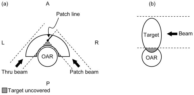
The two geometries of target volumes and organs at risk that represent challenges for proton therapy, even when the field patching technique is employed. (a) Concave target partially surrounding convex OAR. For this illustration only PA and P-lateral oblique fields are allowed. The dashed lines represent the projection of the collimator opening and the grey shaded areas identify the portions of the target left uncovered. (b) OAR partially surrounding the target or target infiltrating the OAR. A = Anterior; P = Posterior; L = Left Lateral; R = Right Lateral. AP identifies the anteroposterior axis, LR the left-right lateral axis. The third major anatomical axis is the superior-inferior (SI).
First we consider a convex organ at risk surrounded totally or partially by the target volume (figure 1(a)). This would typically be treated with binary field patching in 3DCPT. However, despite best efforts, the patch combination could still leave a portion of the target uncovered. This is particularly true when certain beam directions are prohibited by patient-specific constraints as assumed in the figure (only PA and P-lateral oblique fields are allowed). The lateral beam penumbra would still deliver a non-zero dose to the portion of the target just behind the edges of the collimator opening, but certainly not the prescribed dose. A significant cold spot (local underdose) could occur.
The second scenario is characterized by the tumor infiltrating the OAR as in figure 1(b). Here, patching may not even be considered since it would not be able to improve dose conformity without sacrificing the OAR. The resulting plan would be characterized by either a significant target underdose or a significant hot spot (local overdose) in the OAR.
It should be noted that for geometries in the head-and-neck region similar to figure 1(a) the use of lateral fields is often allowed to improve coverage anterior to the OAR. A typical beam configuration in these cases would alternate a right- with a left-lateral thru fields in combination with a posterior-right lateral and a posterior-left lateral patch field.
2.2 Patient examples
Two patients treated at FHBPTC were selected for this study. Table 1 summarizes the clinical plans for both patients. The standard clinical 3DCPT plans were created with XiO planning software (CMS Inc., St. Louis, MO, USA).
Table 1.
Clinical 3DCPT treatment plans for the two patients used in this study.
| Patient | Prescribed Proton dose | Fields | Patching combinations | Dose delivered with patching (% of total prescribed proton dose) | Comment |
|---|---|---|---|---|---|
| paraspinal chondrosarcoma | 27 Gy (RBE) | 4 | 2 | 100% | Boost following photon therapy |
| skull base chondrosarcoma | 69 Gy (RBE) | 9 | 2 | 17% | Pediatric patient. Patching: boost to GTV after initial proton therapy |
The first patient case, the chondrosarcoma of the T4 vertebral body (figure 2), is representative of the scenario depicted in figure 1(a). The clinical plan was designed to boost the gross tumor volume (GTV) with 27 Gy (RBE)4 using only posterior oblique beams. The constraints for the spinal cord were 9 Gy (RBE) to the surface and 3 Gy (RBE) to the center. Lateral fields could not be employed because they would require irradiation through the lungs, associated with high range uncertainty. Inspection of the projection of the aperture edges in figure 2(b) confirms that at least two different portions of the GTV were not directly exposed to radiation under any of the fields. For this reason severe cold spots were expected both anterior and left-lateral to the spinal cord.
Figure 2.
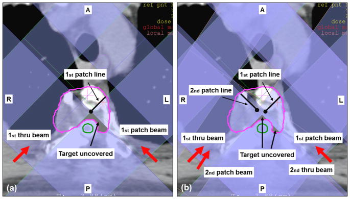
Paraspinal chondrosarcoma patient. Boost with protons after receiving photon therapy. Target in pink and spinal cord in green. Red arrows refer to beam directions and black arrows to labels. Shading of beams show projection of the aperture edges as obtained from the XiO planning system. The clinical plan consisted of 2 patch combinations involving 4 beams in total. (a) First patch combination used two posterior oblique beams with beam angles 225° and 135° (b) Both patch combinations are shown. Two posterior oblique beams are used also for the second patch combination with beam angles 215° and 135°.
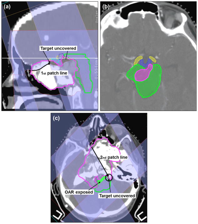
The second patient case, the skull-base case (figure 3), received a full proton treatment with 9 fields. This patient is representative of both scenarios in figure 1. Two different patch combinations were employed in the effort to spare the brainstem, the optical system, the chiasm and the hypothalamus. For this patient too, a significant cold spot in the target was expected, while the constraints to some OAR had to be relaxed (e.g. up to 70 Gy to the surface of the brainstem was allowed). Note that only one-sixth of the total dose was delivered with patching.
Figure 3.
Skull-base chondrosarcoma. Target in pink, brainstem in green, chiasm in cyan, hypothalamus in blue and right optical tracks in yellow. (a) Sagittal view of the first patch combination consisting of a superior-anterior beam (gantry/couch angle 70°/270°) and a left-superior-anterior beam (70°/350°). (b) Axial view corresponding to the plane identified by the horizontal solid white line in (a). (c) Axial view of the second patch combination consisting of a left-posterior beam (150°/0°) and a right-posterior beam (225°/0°). The other beams are 270°/0°, 80°/0°, 210°/0°, 280°/65° and 270°/10°. Note: for the IMPT plan the following 4 beams were used, i.e., 270°/0°, 80°/0°, 210°/0°, 280°/65°.
2.3 The patching technique in 3DCPT and inherent limitations
In binary patching, dose uniformity is primarily limited because of the different dose gradients in the lateral and distal edge of the two fields along the match line, while it is further compromised by the effects of setup errors and range uncertainties. Therefore, for a given patching combination, dose fluctuation larger than 30% can easily occur (figure 4). Because of the complications along the patch junction, an experienced planner follows specific guidelines in selecting beam directions, which are: always design two or more patch combinations with non-overlapping patch junctions (a patch combination will be used at most 5 times); always keep the patching cross point (marked with a black circle in figure 1(a) outside critical structures; ensure a minimum field aperture size of 2×2 cm2; consider all other principles that apply in 3DCPT such as, avoid the beams through moving organs, keep the air gap between collimator and patient as small as possible, favor the use of the lateral fall-off to spare critical organs rather than the distal-edge. Hence, the number of required and designed fields increases substantially, while the flexibility in beam selections is reduced. Due to the uncertainties in dose at the junction volume, it is common practice at our center, to deliver no more than 15 Gy (RBE) per patch combination, while most of the dose is delivered with non-patch fields. Because of the large number of beams involved, sometimes over a dozen, and the necessity, often, to segment the volume manually, keeping the proper overview and finding the optimal solution, using this technique, can be very challenging and time consuming even for the most experienced planner.
Figure 4.
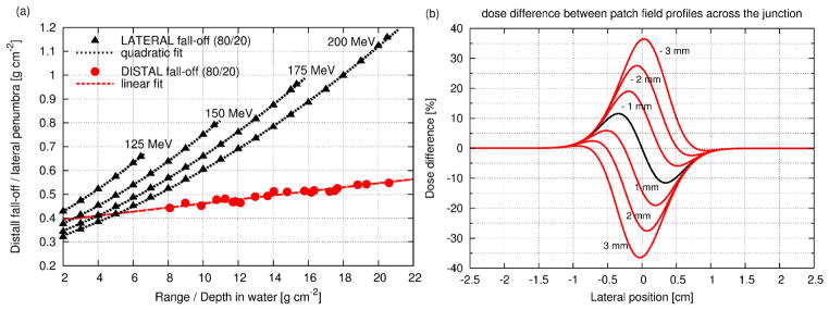
(a) 80%-to-20% distal fall-off (red) measured at FHBPTC as a function of proton range; 80%-to-20% lateral penumbra (black) as a function of depth in water for four different initial energy for a typical double scattered beam using the model of Safai et al. (2008). (b) Transversal profile of the dose fluctuation for matching fields (black solid line) but with different fall-offs (lateral fall-off 1.6 times the distal one); the red solid lines are for mismatched fields, dispaced by between -3 and 3 mm; negative values mean the thru and patch field overlap causing overdose in the target and positive values mean gap between thru and patch field causing underdose.
2.4 IMPT planning in this study
Our study considers the fully 3-dimensional (3D) IMPT method, in which the Bragg peaks are distributed in 3D throughout the target volume for each beam direction. All beamlets for all beam directions are then optimized simultaneously. The 3D approach provides the greatest flexibility in IMPT and is superior especially when few beam directions are employed (Lomax 1999). It has been shown that the 3D approach is also more robust against treatment uncertainties such as range uncertainties, inter-fraction motion and inter-field motion when compared to distal-edge-tracking (Lomax 2008a, Lomax 2008b). IMPT planning was performed with the inverse treatment planning system KonRad Pro (German Cancer Research Center, Germany, see Oelfke and Bortfeld 2001, Nill 2001) assuming spot scanning (Pedroni et al. 1995) with pencil beams spaced transversally by 5 mm. If not otherwise specified a 5 mm pencil beam was used (σ0 at the patient skin). For the paraspinal case the impact of the pencil beam size on the outcome of the optimization process was also investigated by comparing plans obtained with different σ0, i.e., 3, 5, 7, 10, 12 and 16 mm. The number of fields was reduced with respect to the clinical plan, i.e., 2 beams instead of 4 for the paraspinal case and 4 beams instead of 9 for the skull-base case. The beam angles were selected from those used in the clinical plans. For the paraspinal case: gantry angles 225°, 135° and zero couch angle. For the skull-base gantry/couch angles were: 270°/0°, 80°/0°, 210°/0°, 280°/65°.
2.5 Analysis of dose sensitivity to setup errors and range uncertainties
A sensitivity analysis with respect to setup errors and range uncertainties was performed for both the IMPT and 3DCPT plans. Since dose fluctuations due to random setup errors may cancel out during the course of treatment, this study is confined to systematic errors of the order of only 1 mm (Engelsman et al. 2005). Dose calculations were repeated by shifting the beam isocenter along the three major anatomical axis (AP, LR, SI) by ± 1 mm while applying the same intensity distribution as for the nominal IMPT plan and the same range compensators, apertures and beam weights as for the nominal 3DCPT plan. For the range uncertainty analysis dose calculations were repeated with the nominal range changed by ± 2.5 mm for all beam energies. Hence, for each modality and for each patient a total of 9 plans have been evaluated (1 nominal plan, 6 for setup errors and 2 for range uncertainties).
3. Results
3.1 Nominal plan comparison for the paraspinal case
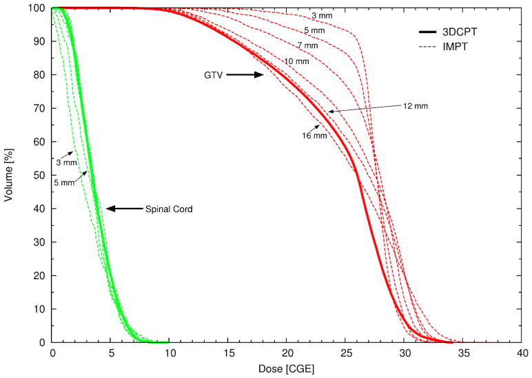
Figure 5 illustrates severe cold spots in the target volume in the 3DCPT plan, which are unavoidable if one aims to keep the spinal cord dose within tolerance. IMPT provides a substantial improvement of target coverage and dose homogeneity for small pencil beams. For pencil beams larger than 10 mm, the advantage of IMPT has virtually disappeared. We note also that for small pencil beams (σ0 < 7 mm) the most difficult constraint to be satisfied was the dose to the surface of the spinal cord, whereas for larger pencil beams it was the dose in the cord-center. Their values were set by steering the maximum and the mean dose respectively. The penalty factors had to be adjusted accordingly during the planning process. This is understandable since the lateral-beam penumbra increases with increasing σ0. The few-millimetre margin between the surface and the center of the spinal cord requires very sharp dose gradients in order to satisfy both constraints simultaneously, which can be achieved only with small pencil beams. Figure 6 illustrates three major positive aspects of the IMPT plan with respect to the clinical one. First, by allowing a hot spot in the target anterior to the spinal cord (white arrow in figure 6(a), the nearby cold area is reduced. Second, both the right-posterior and left-posterior beams contribute to the dose on the left side of the spinal cord, which also helps to improve coverage. Third, the dose gradient in the overlapping area is reduced compared to the gradients at a patch junction.
Figure 5.
DVHs of patient 1 (paraspinal case) for the GTV (red) and the spinal cord (green) for the clinical 3DCPT plan (solid line) and for several IMPT plans (dashed lines) optimized using pencil beams of varying sizes (σ). The pencil beam sizes (between 3 mm and 16 mm) at the patient skin are explicitly reported.
Figure 6.
IMPT plan for the paraspinal case using a 5mm (σ) pencil beam. (a) Total dose. (b) Dose from posterior-right lateral beam. (c) posterior-left lateral beam
3.2 Nominal plan comparison for the skull-base case
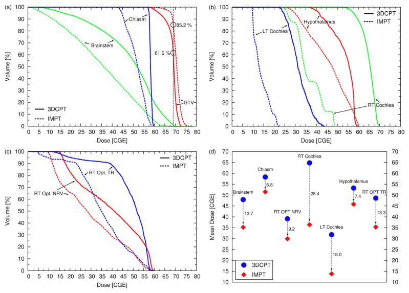
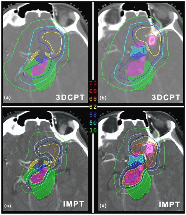
IMPT was able to improve the plan quality substantially as shown in figure 7. The target coverage is improved (V69GyRBE = 85.2% as opposed to 61.6%) and the benefit to the OARs is remarkable: the reduction of the mean dose to all OARs ranges between 6.8 Gy (RBE) (chiasm) and 28.4 Gy (RBE) (right cochlea). The maximum dose to most of the OAR is also reduced, including the brainstem and chiasm. This is a good example that shows that the inherent flexibility of IMPT to modulate the dose for each beam gives the opportunity to reach areas which seem to be inaccessible with classic 3DCPT. Areas as those depicted in figure 8 are in fact extremely challenging to cover without sacrificing the OARs. Figure 8(a) shows that the target is surrounded by the OARs, i.e., the brainstem, hypothalamus, chiasm, optical tracks, and consequently the clinical plan failed to deliver the required target dose (the dose to the GTV is between 58 and 62 Gy (RBE)). The IMPT plan, on the other hand, is able to keep the GTV dose above 62 Gy (RBE) in more than 99% of the volume, approaching the prescribed dose in the center (figure 8(c)). At the same time the brainstem and the other OARs are clearly better spared by means of sharper dose gradients (consider for instance the 50 Gy (RBE) and 30 Gy (RBE) isolines). Similar results are illustrated in figure 8(b) and 8(d). It should be noted that for the IMPT plan we used only 4 beams as opposed to 9 (clinical plan), and the directions of the 4 beams were selected from the clinical plan.
Figure 7.
(a–c) DVHs of patient 2 (skull-base case) for the clinical 3DCPT plan (solid lines) and for the IMPT plan (dashed lines). (d) Mean dose to all OARs. The dashed arrows with the associated values emphasize the reduction of the mean dose in Gy (RBE) achieved with the IMPT plan.
Figure 8.
(a) and (b) show the dose distribution for the clinical plan for two different axial slices for patient 2 (skull-base case). (c) and (d) are the same as (a) and (b) but for the IMPT plan. The unit of the isolines is Gy (RBE). The shaded regions identify the GTV (pink) and the OARs, i.e., the brainstem (green), hypothalamus (blue), chiasm (cyan), optical tracks (yellow). Axial slice thickness of 1.25 mm.
3.3 Sensitivity analysis for the paraspinal case
The largest effect due to setup errors is observed if the beam isocenter is shifted in the AP direction since, in that case, the spinal cord is set closer to the edges of all beams. In figure 9(a) the DVHs for the nominal case are compared to the DVHs calculated with an isocenter shift of 1 mm in the AP and PA direction respectively. For both modalities the variations in target coverage relative to the nominal plans are similar. Hence, the superiority of IMPT with respect to GTV coverage remains unaffected by setup errors. For the AP-shift the GTV coverage improves but at the same time the dose delivered to the spinal cord increases exceeding the tolerances, with the largest effect observed for IMPT. Figure 9(b) shows a similar plot but for range errors of ± 2.5 mm. Here the degradation of target coverage is severe for both modalities, but the coverage still remains superior for IMPT. For the 3DCPT plan under range uncertainties the dose to the spinal cord is not affected because the lateral penumbra is used to spare this organ. For the IMPT plan, the effect is moderate, indicating that only a few pencil beams stop in front of the OAR.
Figure 9.
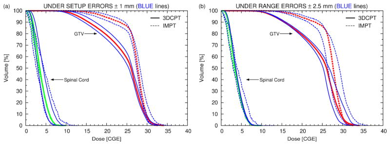
(a) DVHs of the paraspinal patient for the nominal 3DCPT (solid lines) and nominal IMPT (dashed lines) plans (red for the GTV and green for the spinal cord) and for 4 additional plans recalculated under setup errors of 1 mm in the AP and PA direction respectively, i.e., 2 for 3DCPT (solid blue lines) and 2 for IMPT (dashed blue lines). (b) Similar plot to (a) but for range errors
3.4 Sensitivity analysis for the skull-base case
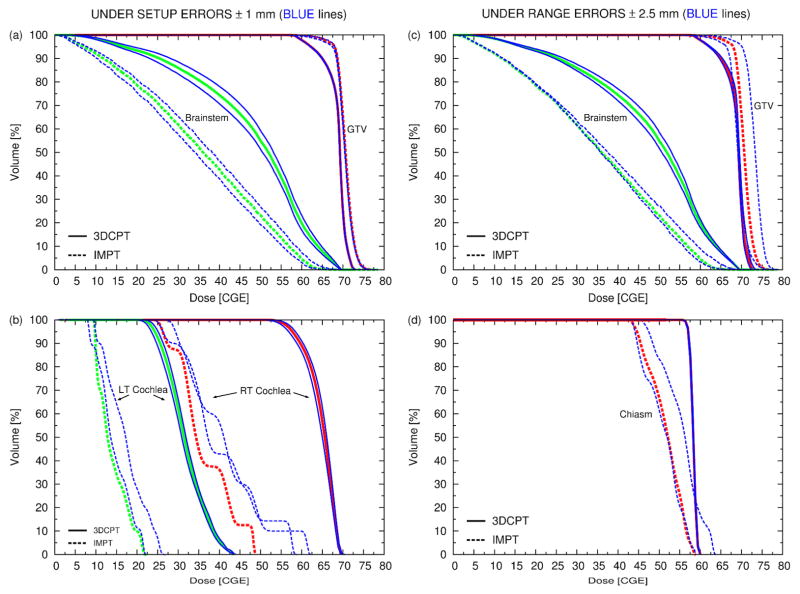
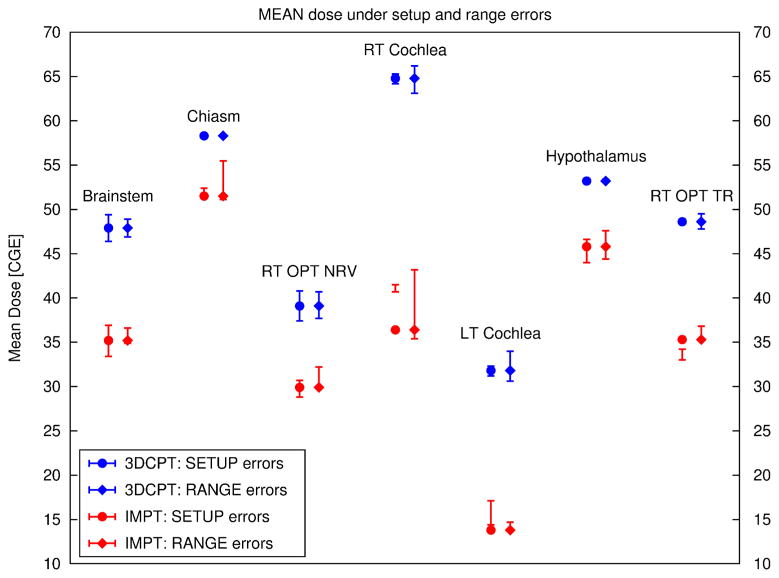
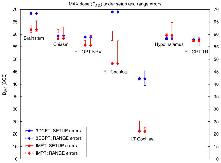
Figure 10(a–b) shows the results for setup errors in the AP, PA direction and figure 10(c–d) those for range errors for several structures. Figure 11 summarizes the results for the mean dose to all OARs for both sources of uncertainty and figure 12 shows the same but for the max dose.
Figure 10.
same as figure 9 but for the skull-base case. Note that (a) and (b) refer to setup errors and (c) and (d) to range errors.
Figure 11.
Mean dose for all organs at risk of the skull-base case for 3DCPT (blue) and IMPT (red). The errors bars connect the mean dose values for a specific organ observed under a given uncertainty, i.e, setup error of 1 mm in the AP, PA direction and range errors of ± 2.5 mm. For instance, let us consider the error bars under setup errors for the RT Cochlea for IMPT: the mean dose to the RT Cochlea under 1 mm AP-shift is 40.7 Gy (RBE) and under 1 mm PA-shift is 41.5 Gy (RBE). In the plot these two values are connected with a vertical line. Note that the mean dose to the RT Cochlea for the nominal plan (full-red circle) is only 36.4 and therefore it is located below the error bars. This shows that the RT Cochlea of the IMPT plan is sitting in a hollow of the dose distribution.
Figure 12.
Maximum dose for all organs at risk of the skull-base case for 3DCPT (blue) and IMPT (red). Here the maximum dose is defined as the dose to 2% of the volume (D2%) of the DVH. The errors bars connect the max dose values for a specific organ observed under a given uncertainty, i.e, setup error of 1 mm in the AP, PA direction and range errors of ± 2.5 mm. See also caption to figure 11.
3.4.1 Setup errors (figure 10(a–b))
Unlike in the paraspinal case, the target coverage is rather insensitive to setup errors of the order of 1 mm. Again the target coverage of IMPT is still superior. In general, larger variations of the OAR dose are observed for IMPT except for the mean dose to the right optic nerve (see also figure 11). This could be explained by the observation that the dose delivered to the OAR in IMPT is typically less homogenous than that delivered with 3DCPT (e.g., right (RT) cochlea, chiasm). For small organs, which are not in close proximity to the target, such as left and RT cochlea, IMPT is efficient at creating cold spots that conform to these small volumes. Hence, any motion of these organs in any possible direction would then cause an increase in dose. On the other hand, for the right optical tracks the opposite is true, i.e., a small decrease in dose is observed, likely, due to the proximity of other OARs, which together generated a complicated dose pattern.
3.4.2 Range errors (figure 10(c–d))
The GTV coverage is more sensitive to range errors than to setup errors, especially for IMPT for which up to 3 % overall dose increase (shift of the entire DVH) for range overshoot and 2 % dose decrease for range undershoot is observed. No general trend was observed for the dose delivered to the OAR under range errors. In the 3DCPT plan, the chiasm and hypothalamus (not shown) appear insensitive to range variations, while in the IMPT plan, they show a substantial sensitivity to range overshoots (see also figure 12). Around 20% of the volume could receive doses larger than those delivered with the clinical plan and, hence, could exceed tolerances.
Even though figure 11 seems to testify that for both setup and range errors below 2.5 mm the IMPT clearly remains superior to the 3DCPT plan, the review of the DVHs shows the potential risk of larger range overshoots for the IMPT plan, which may increase the maximum dose delivered to a specific organ as shown also in figure 12.
4. Discussion
4.1 Where can IMPT make a difference?
The delivery of many patching fields from different directions could, in principle, overcome the difficulty of generating convex-concave dose distributions to achieve results similar to IMPT. However, this approach is not practical in the clinic for two reasons. First, because additional fields increase the planning, QA- and treatment time considerably and, second, the number of possible patch combinations is limited by several factors such as tumour position and size. Hence, for a number of patients with geometries similar to those depicted in figure 1, the target coverage falls short. These patients could benefit from the higher flexibility of IMPT, which could improve the plan quality drastically with a reduced number of beams, as shown in the clinical examples in this study.
The binary dose distribution, which is the fundamental component of the patching technique, has, by definition, an important drawback, i.e., very sharp dose gradients within the target volume for each individual beam. Therefore, up to date, this technique is used only to boost the target volume or to deliver a fraction of the total dose. On this note, the paraspinal case showed that a boost with patching compared to a boost with IMPT exhibits similar sensitivity of target coverage to setup errors and range uncertainties. Nevertheless, IMPT, has the ability to produce smoother dose gradients, especially if robust optimization techniques are employed (Unkelbach et al. 2007, Pflugfelder et al. 2008, Chen et al. 2012), which would give the opportunity to deliver IMPT for the entire course of treatment rather than just for a small number of fractions. Unkelbach et al. (2007) showed for instance, that for a typical two-beam patch-field arrangement such as the one depicted in figure 1(a), IMPT is able to provide very smooth dose gradients throughout the overlapping region when robust optimization is applied as opposed to 3DCPT.
4.2 The effect of treatment uncertainties and possible mitigation techniques
We expect that if a clear a priori benefit of IMPT is observed in nominal plans, the use of IMPT in its most simple manifestation i.e., without including robust techniques, remains attractive over sophisticated 3DCPT, i.e. use of patching fields, even when taking into account the effects of setup errors and range uncertainties on the dose distribution (figure 11). Nevertheless, we cannot ignore the risk of range overshoots especially for IMPT (figure 10(d)). A physician may be willing to accept an overall dose increase to the target of the order of 3% but he or she may be less inclined to accept the risk of an increase of the maximum dose to certain serial organs, such as, in our example, the chiasm and hypothalamus. Potential risks have to be identified by performing suitable sensitivity analysis and action should be taken in advance if necessary. Even though we are in favour of the implementation of robust optimization techniques, other simpler approaches could be employed in the attempt to protect the OAR, such as the use of a secure margin around the OAR. ICRU Report 62 (1999) calls this the “Planning Risk Volume” (PRV). Since, often, the tissue around the OAR is unclassified, and it is not subject to any constraint, the optimization process may place unnecessary Bragg peaks in the neighbourhood of the OAR. The PRV could help to suppress these potentially harmful Bragg peaks without necessarily compromising target coverage, especially if the OAR is not directly in contact with the target (e.g. the right cochlea for the skull-base case). If the most critical direction for setup error can be identified (e.g. AP-shift for the paraspinal case) by performing analysis similar to ours, then particular care could be given in positioning the patient along that direction possibly by improving or redesigning dedicated immobilization devices.
In vivo range verification is an exciting development, which is currently explored but is yet far from being mature for clinical routine. Proton radiography (Schneider and Pedroni 1994, Schneider et al. 2005), PET measurements after irradiation (Parodi and Bortfeld 2006, Knopf et al. 2011a) and prompt-gamma measurements (Min et al. 2006) can potentially be used. Precise range verifications could provide better understanding of the magnitude and distribution of range uncertainties, which in turn would provide realistic inputs to use in robust optimization methods. It would also provide the necessary confidence to fully realize the potential of proton therapy, i.e., the use of the sharp distal fall-off to shape the dose.
4.3 The need for sensitivity analysis tools in the clinic
The sensitivity study presented here required substantial manual work since the current treatment planning package is not yet designed to support it. Unlike with photons, the static dose cloud assumption5 is not valid because of the finite proton range. Therefore the dose distribution for each geometrical instance had to be recomputed by creating a separate plan for each instance, which was laborious especially for the 3DCPT plans. A platform to automatize the entire process is desirable and necessary in proton therapy so that a larger spectrum of scenarios could be investigated, e.g. impact of the motion of the patient between different fields during the same fraction (inter-field errors). The same platform should include new dose-visualization and dose-reporting tools (e.g., Albertini et al. 2011, Hild et al. 2012). In this regard, Lomax (2008b) introduced methods for evaluating the effects of inter-fraction and inter-field positional errors based on a worst-case analysis (Lomax et al. 2004). The worst-case approach, as noted by the author himself, has the drawback to generate unphysical dose distributions and as such it finds its best application essentially as a comparative tool between different plans rather than as a method for evaluating the effects of positional errors for one particular plan alone. Nevertheless, the worst-case approach has found an interesting application in the robust optimization of IMPT plans in a study by Pflugfelder et al. (2008).
4.4 The role of planning parameters in IMPT
The outcome of the optimization process depends strongly on the underlying parameters and assumptions, among which the most significant are: the pencil beam lateral size (σ0), the starting conditions (e.g. plan objectives, penalty factors, priorities, initial beamlet fluences (Albertini et al. 2010)) for the optimization, the model used to describe the delivery uncertainties, and the choice of IMPT planning method itself. The implementation of multicriteria optimization (MCO) (Craft et al. 2007) allows one to explore the horizon of optimal treatment plans corresponding to different constraints and penalties, simplifies the search of the best outcome and has been shown to improve planning efficiency (Craft et al. 2012). Little room is left in the choice of σ0 since it is dictated by the performance of the beam delivery system. Figure 5 shows how much better a small pencil beam (σ0 of 5 mm or less) performs compared to a larger one. Because only posterior-oblique fields could be employed, the transversal edge played the key role in sparing the spinal cord for both techniques, and therefore large pencil beam turned out to be less attractive. For other sites, however, IMPT could create dose conformity by exploiting the distal fall-off (which is normally steeper), making the plan quality less sensitive to the achievable lateral σ0. The drawback is then that the plan is more sensitive to range overshoots. Unkelbach et al. (2007) showed that if robust optimization against range uncertainties is employed, the situation reverts by favouring again the lateral penumbra. Hence, for robust plans under range uncertainties the lateral edge returns to play a key role making small pencil beams desirable. In this regard Safai et al. (2008) discussed the impact of the pencil beam size on the lateral penumbra.
The freedom to decide whether to use the lateral penumbra or the distal fall-off is again only a prerogative of IMPT, i.e., of the ability to create an inhomogeneous dose pattern for any given beam direction. To illustrate this let us consider again the example depicted in figure 1(a). But this time, we assume that only anterior-oblique beams are allowed instead of posterior-oblique beams. For this configuration Lomax et al. 2001 showed how inhomogeneous doses per field are able to produce a total homogenous coverage by favouring the lateral penumbra in the presence of range uncertainties (the configuration was called “proximal patching”). By no means this would be possible with any given binary patch combination. This is again an important advantage of IMPT. It should be noted that sharpening the lateral penumbra with proper modulation, i.e., by increasing the weight of pencil beams at the field edge, is, on the other hand, an advantage of scanning rather than of IMPT. As a matter of fact, edge enhancement with scanning can be successfully realized without deteriorating the dose homogeneity in a given field (Trofimov and Bortfeld 2003, Pedroni 2008). Another interesting aspect is that, the dose to normal tissue proximal to the target can potentially be improved if, again, non-uniform dose distributions are used.
5. Conclusions
IMPT can potentially improve target coverage and OAR sparing in challenging configurations even compared to the patching technique. While IMPT plans tend to be more sensitive to errors, the advantage holds for the cases studied, but dose sensitivity analysis is recommended for each individual case to ensure safe delivery of proton therapy field matching (both patching and IMPT). Optimized IMPT solutions are influenced both by the parameters of the delivery system (e.g., beam size, delivering mode) and the assumptions about delivery uncertainty (e.g. range vs lateral shift vs combined). The results of the sensitivity analysis are also defined by the uncertainty model. New planning techniques can reduce the IMPT sensitivity to errors, as long as the model is valid.
Footnotes
In this paper we use a value for the relative biological effectiveness of protons of RBE=1.1 throughout (ICRU 2007).
Under this assumption the target dose distribution in the room coordinate system delivered by multiple photons beams remains invariant under small displacements of the patient.
References
- Albertini F, Hug EB, Lomax AJ. The influence of the optimization starting conditions on the robustness of intensity-modulated proton therapy plans. Phys Med Biol. 2010;55:2863–78. doi: 10.1088/0031-9155/55/10/005. [DOI] [PubMed] [Google Scholar]
- Albertini F, Hug EB, Lomax AJ. Is it necessary to plan with safety margins for actively scanned proton therapy. Phys Med Biol. 2011;56:4399–413. doi: 10.1088/0031-9155/56/14/011. [DOI] [PubMed] [Google Scholar]
- Bortfeld T. IMRT: a review and preview. Phys Med Biol. 2006;51:R363–R379. doi: 10.1088/0031-9155/51/13/R21. [DOI] [PubMed] [Google Scholar]
- Bussiere MR, Adams JA. Treatment Planning for Conformal Proton Radiation Therapy. Tech Cancer Res Treat. 2003;2:389–99. doi: 10.1177/153303460300200504. [DOI] [PubMed] [Google Scholar]
- Chen W, Unkelbach J, Trofimov A, Madden T, Kooy H, Bortfeld T, Craft D. Including robustness in multi-criteria optimization for intensity-modulated proton therapy. Phys Med Biol. 2012;57:591–608. doi: 10.1088/0031-9155/57/3/591. [DOI] [PMC free article] [PubMed] [Google Scholar]
- Craft DL, Halabi T, Shih HA, Bortfeld T. An approach for practical multiobjective imrt treatment planning. Int J Radiat Oncol Biol Phys. 2007;69:1600–07. doi: 10.1016/j.ijrobp.2007.08.019. [DOI] [PubMed] [Google Scholar]
- Craft DL, Hong TS, Shih HA, Bortfeld TR. Improved planning time and plan quality through multicriteria optimization for intensity-modulated radiotherapy. Int J Radiat Oncol Biol Phys. 2012;82:e83–e90. doi: 10.1016/j.ijrobp.2010.12.007. [DOI] [PMC free article] [PubMed] [Google Scholar]
- Engelsman M, Rosenthal SJ, Michaud SL, Adams JA, Schneider RJ, Bradley SG, Flanz JB, Kooy HM. Intra- and inter-fractional patient motion for a variety of immobilization devices. Med Phys. 2005;32:3468–74. doi: 10.1118/1.2089507. [DOI] [PubMed] [Google Scholar]
- Hild S, Durante M, Bert C. Assessment of uncertainties in treatment planning for scanned ion beam therapy of moving tumors. Int J Radiat Oncol Biol Phys. 2012 doi: 10.1016/j.ijrobp.2012.04.011. Epub ahead of print. [DOI] [PubMed] [Google Scholar]
- ICRU. ICRU Report 62. Bethesda, MD: 1999. Prescribing, Recording and Reporting Photon Beam Therapy (Supplement to ICRU Report 50) [Google Scholar]
- ICRU. ICRU Report 78. Bethesda, MD: 2007. Prescribing, Recording and Reporting Proton-Beam Therapy. [Google Scholar]
- Knopf A, Parodi K, Paganetti H, Bortfeld T, Daartz J, Engelsman M, Liebsch N, Shih H. Accuracy of proton beam range verification using post-treatment positron emission tomography/computed tomography as function of treatment site. Int J Radiat Oncol Biol Phys. 2011a;79:297–304. doi: 10.1016/j.ijrobp.2010.02.017. [DOI] [PubMed] [Google Scholar]
- Knopf A, Hong TS, Lomax A. Scanned proton radiotherapy for mobile targets – the effectiveness of re-scanning in the context of different treatment planning approaches and for different motion characteristics. Phys Med Biol. 2011b;56:7257–71. doi: 10.1088/0031-9155/56/22/016. [DOI] [PubMed] [Google Scholar]
- Lomax A. Intensity modulation methods for proton radiotherapy. Phys Med Biol. 1999;44:185–205. doi: 10.1088/0031-9155/44/1/014. [DOI] [PubMed] [Google Scholar]
- Lomax A, Boehringer T, Coray A, Egger E, Goitein G, Grossmann M, Juelke P, Lin S, Pedroni E, Rohrer B, Roser W, Rossi B, Siegenthaler B, Stadelmann O, Stauble H, Vetter C, Wisser L. Intensity modulated proton therapy: A clinical example. Med Phys. 2001;28:317–24. doi: 10.1118/1.1350587. [DOI] [PubMed] [Google Scholar]
- Lomax AJ, Pedroni E, Rutz HP, Goitein G. The Clinical Potential of Intensity Modulated Proton Therapy. Z Med Phys. 2004;14:147–52. doi: 10.1078/0939-3889-00217. [DOI] [PubMed] [Google Scholar]
- Lomax AJ. Intensity modulated proton therapy and its sensitivity to treatment uncertainties 1: the potential effects of calculational uncertainties. Phys Med Biol. 2008a;53:1027–42. doi: 10.1088/0031-9155/53/4/014. [DOI] [PubMed] [Google Scholar]
- Lomax AJ. Intensity modulated proton therapy and its sensitivity to treatment uncertainties 2: the potential effects of inter-fraction and inter-field motions. Phys Med Biol. 2008b;53:1043–56. doi: 10.1088/0031-9155/53/4/015. [DOI] [PubMed] [Google Scholar]
- Min CH, Kim CH, Youn MY, Kim JW. Prompt gamma measurements for locating the dose falloff region in the proton therapy. Appl Phys Lett. 2006;89:183517. [Google Scholar]
- Nill S. PhD Thesis. University of Heidelberg; Heidelberg: 2001. Development and application of a multi-modality inverse treatment planning system. [Google Scholar]
- Oelfke U, Bortfeld T. Inverse planning for photon and proton beams. Med Dosim. 2001;26:113–24. doi: 10.1016/s0958-3947(01)00057-7. [DOI] [PubMed] [Google Scholar]
- Parodi K, Bortfeld T. A filtering approach based on Gaussian-powerlaw convolutions for local PET verification of proton radiotherapy. Phys Med Biol. 2006;51:1991–2009. doi: 10.1088/0031-9155/51/8/003. [DOI] [PubMed] [Google Scholar]
- Pedroni E, Bacher R, Blattmann H, Böhringer T, Coray A, Lomax A, Lin S, Munkel G, Scheib S, Schneider U, Tourovsky A. The 200-MeV proton therapy project at the Paul Scherrer Institute: Conceptual design and practical realization. Med Phys. 1995;22:37–53. doi: 10.1118/1.597522. [DOI] [PubMed] [Google Scholar]
- Pedroni E. Pencil Beam Scanning. In: DeLaney TF, Kooy HM, editors. Proton and Charged Particle Radiotherapy. Lippincott Williams and Wilkins, a Wolter Kluwer business; 2008. pp. 41–9. [Google Scholar]
- Pedroni E, Meer D, Bula C, Safai S, Zenklusen S. Pencil beam characteristics of the next-generation proton scanning gantry of PSI: design issues and initial commissioning. Eur Phys J Plus. 2011;126:66. [Google Scholar]
- Pflugfelder D, Wilkens JJ, Oelfke U. Worst case optimization: a method to account for uncertainties in the optimization of intensity modulated proton therapy. Phys Med Biol. 2008;53:1689–1700. doi: 10.1088/0031-9155/53/6/013. [DOI] [PubMed] [Google Scholar]
- Safai S, Bortfeld T, Engelsman M. Comparison between the lateral penumbra of a collimated double-scattered beam and uncollimated scanning beam in proton radiotherapy. Phys Med Biol. 2008;53:1729–50. doi: 10.1088/0031-9155/53/6/016. [DOI] [PubMed] [Google Scholar]
- Schneider U, Pedroni E. Proton radiography as a tool for quality control in proton therapy. Med Phys. 1994;22:353–63. doi: 10.1118/1.597470. [DOI] [PubMed] [Google Scholar]
- Schneider U, Agosteo S, Pedroni E, Besserer J. Secondary neutron dose during proton therapy using spot scanning. Int J Radiat Oncol Biol Phys. 2002;53:244–51. doi: 10.1016/s0360-3016(01)02826-7. [DOI] [PubMed] [Google Scholar]
- Schneider U, Pemler P, Besserer J, Pedroni E, Lomax A, Kaser-Hotz B. Patient specific optimisation of the relation between CT-Hounsfield units and proton stopping power with proton radiography. Med Phys. 2005;32:195–99. doi: 10.1118/1.1833041. [DOI] [PubMed] [Google Scholar]
- Trofimov A, Bortfeld T. Optimization of Beam Parameters and Treatment Planning for Intensity Modulated Proton Therapy. Tech Cancer Res Treat. 2003;2:437–44. doi: 10.1177/153303460300200508. [DOI] [PubMed] [Google Scholar]
- Unkelbach J, Chan TCY, Bortfeld T. Accounting for range uncertainties in the optimization of intensity modulated proton therapy. Phys Med Biol. 2007;52:2755–73. doi: 10.1088/0031-9155/52/10/009. [DOI] [PubMed] [Google Scholar]
- Zenklusen SM, Pedroni E, Meer D. A study on repainting strategies for treating moderately moving targets with proton pencil beam scanning at the new Gantry 2 at PSI. Phys Med Biol. 2010;55:5103–21. doi: 10.1088/0031-9155/55/17/014. [DOI] [PubMed] [Google Scholar]


