Abstract
Spintronics is an emerging paradigm with the aim to replace conventional electronics by using electron spins as information carriers. Its utility relies on the magnitude of the spin-relaxation, which is dominated by spin-orbit coupling (SOC). Yet, SOC induced spin-relaxation in metals and semiconductors is discussed for the seemingly orthogonal cases when inversion symmetry is retained or broken by the so-called Elliott-Yafet and D'yakonov-Perel' spin-relaxation mechanisms, respectively. We unify the two theories on general grounds for a generic two-band system containing intra- and inter-band SOC. While the previously known limiting cases are recovered, we also identify parameter domains when a crossover occurs between them, i.e. when an inversion symmetry broken state evolves from a D'yakonov-Perel' to an Elliott-Yafet type of spin-relaxation and conversely for a state with inversional symmetry. This provides an ultimate link between the two mechanisms of spin-relaxation.
A future spintronics device would perform calculations and store information using the spin-degree of freedom of electrons with a vision to eventually replace conventional electronics1,2,3. A spin-polarized ensemble of electrons whose spin-state is manipulated in a transistor-like configuration and is read out with a spin-detector (or spin-valve) would constitute an elemental building block of a spin-transistor. Clearly, the utility of spintronics relies on whether the spin-polarization of the electron ensemble can be maintained sufficiently long. The basic idea behind spintronics is that coherence of a spin-ensemble persists longer than the coherence of electron momentum due to the relatively weaker coupling of the spin to the environment. The coupling is relativistic and has thus a relatively weak effect known as spin-orbit coupling (SOC).
The time characterizing the decay of spin-polarization is the so-called spin-relaxation time (often also referred to as spin-lattice relaxation time), τs. It can be measured either using electron spin-resonance spectroscopy (ESR)4 or in spin-transport experiments5,6. Much as the theory and experiments of spin-relaxation measurements are developed, it remains an intensively studied field for novel materials; e.g. the value of τs is the matter of intensive theoretical studies7,8,9,10,11,12,13 and spin-transport experiments14,15,16,17 in graphene at present.
The two most important spin-relaxation mechanisms in metals and semiconductors are the so-called Elliott-Yafet (EY) and the D'yakonov-Perel' (DP) mechanisms. These are conventionally discussed along disjoint avenues, due to reasons described below. Although the interplay between these mechanisms has been studied in semiconductors3,18,19,20, no attempts have been made to unify their descriptions. We note that a number of other spin-relaxation mechanisms, e.g. that involving nuclear-hyperfine interaction, are known2,3.
The EY theory21,22 describes spin-relaxation in metals and semiconductors with inversion symmetry. Therein, the SOC does not split the spin-up/down states (|↑〉, |↓〉) in the conduction band, however the presence of a near lying band weakly mixes these states while maintaining the energy degeneracy. The nominally up state reads:  (here ak, bk are band structure dependent) and bk/ak = L/Δ, where L is the SOC matrix element between the adjacent bands and Δ is their separation. E.g. in alkali metals L/Δ ≈ 10−2..10−3 (Ref. 22). Elliott showed using first order time-dependent perturbation theory that an electron can flip its spin with probability (L/Δ)2 at a momentum scattering event. As a result, the spin scattering rate (
 ) reads:
 |
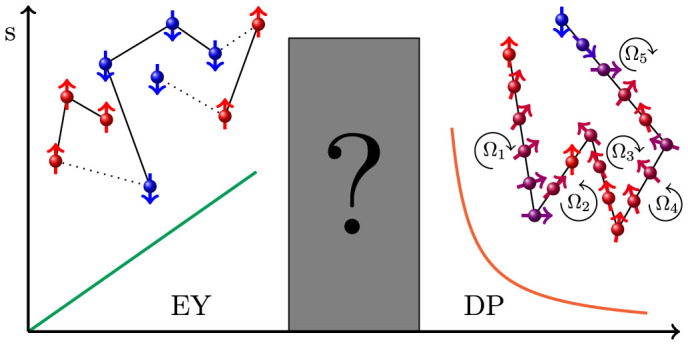
where  is the quasi-particle scattering rate with τ being the corresponding momentum scattering (or relaxation) time. This mechanism is schematically depicted in Fig. 1a.
Figure 1. Schematics of the Elliott-Yafet and the D'yakonov-Perel' mechanisms:  in the EY scenario and spin-scattering occurs rarely (typically for every 104..106th momentum scattering in alkali metals), whereas the spin direction continuously precesses around the internal magnetic field due to SOC in the DP scenario, resulting in
  .
.

It is the topic of the present paper, how these two distinct regimes are related to each other.
For semiconductors with zinc-blende crystal structure, such as e.g. GaAs, the lack of inversion symmetry results in an efficient relaxation mechanism, the D'yakonov-Perel' spin-relaxation23. Therein, the spin-up/down energy levels in the conduction bands are split. The splitting acts on the electrons as if an internal, k-dependent magnetic field would be present, around which the electron spins precess with a Larmor frequency of  . Here
  is the energy scale for the inversion symmetry breaking induced SOC. Were no momentum scattering present, the electron energies would acquire a distribution according to
  . In the presence of momentum scattering which satisfies
  , the distribution is “motionally-narrowed” and the resulting spin-relaxation rate reads:
 |
This situation is depicted in Fig. 1b. Clearly, the EY and DP mechanisms result in different dependence on Γ which is often used for the empirical assignment of the relaxation mechanism24.
The observation of an anomalous temperature dependence of the spin-relaxation time in MgB225 and the alkali fullerides26 and the development of a generalization of the EY theory high-lighted that the spin-relaxation theory is not yet complete. In particular, the first order perturbation theory of Elliott breaks down when the quasi-particle scattering rate is not negligible compared to the other energy scales. One expects similar surprises for the DP theory when the magnitude of e.g. the Zeeman energy is considered in comparison to the other relevant energy scales.
Herein, we develop a general and robust theory of spin-relaxation in metals and semiconductors including SOC between different bands and the same bands, provided the crystal symmetry allows for the latter. We employ the Mori-Kawasaki theory which considers the propagation of the electrons under the perturbation of the SOC. We obtain a general result which contains both the EY and the DP mechanisms as limits when the quasi-particle scattering and the magnetic field are small. Interesting links are recognized between the two mechanisms when these conditions are violated: the EY mechanism appears to the DP-like when Γ is large compared to Δ and the DP mechanism appears to be EY-like when the Zeeman energy is larger than Γ. Qualitative explanations are provided for these analytically observed behaviors.
Results
The minimal model of spin-relaxation is a four-state (two bands with spin) model Hamiltonian for a two-dimensional electron gas (2DEG) in a magnetic field, which reads:
 |
 |
 |
 |
where α = 1 (nearby), 2 (conduction) is the band index with s = (↑), (↓) spin,  is the single-particle dispersion with
  effective mass and Δ band gap, ΔZ = gμBBz is the Zeeman energy.
  is responsible for the finite quasi-particle lifetime due to impurity and electron-phonon scattering and Lα,α′,s,s′(k) is the SOC.
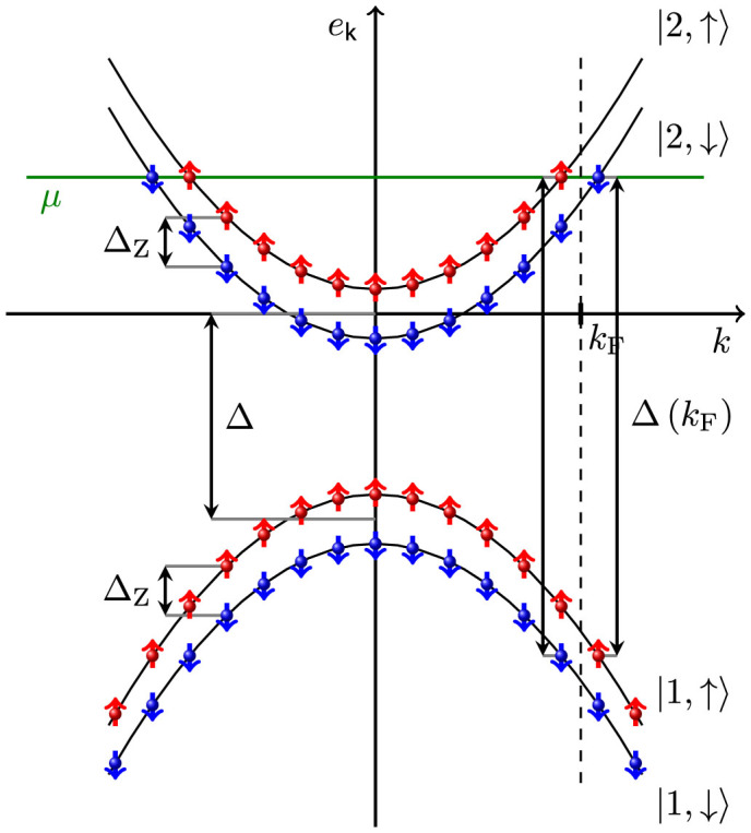
The corresponding band structure is depicted in Fig. 2. The eigenenergies and eigenstates without SOC are
 |
 |
 |
The most general expression of the SOC for the above levels reads:
 |
where  , Lss′(k) are the wavevector dependent intra- and inter-band terms, respectively, which are phenomenological, i.e. not related to a microscopic model. The terms mixing the same spin direction can be ignored as they commute with the Sz operator and do not cause spin-relaxation. The SOC terms contributing to spin-relaxation are
 |
Figure 2. The band structure of a 2DEG in a magnetic field.

The effects of the weak SOC are not shown. Vertical arrows show the energy separations between the relevant bands.
Table I. summarizes the role of the inversion symmetry on the SOC parameters. For a material with inversion symmetry, the Kramers theorem dictates (without magnetic field) that  and thus
  , which term would otherwise split the spin degeneracy in the same band. When the inversion symmetry is broken,
  is finite and the previous degeneracy is reduced to a weaker condition:
  dictated by time reversal symmetry.
Table 1. Effect of the presence or absence of the inversion symmetry on the intra- ( ) and inter-band (L) SOC and on the energy splitting of spin-states in the same band, εk,↑ − εk,↓.
| inversion symmetry | broken inv. symm. | |
|---|---|---|
| 0 | finite | |
| L | finite | finite |
| εk,↑ − εk,↓ | 0 | finite |
We consider the SOC as the smallest energy scale in our model ( , L(kF)), while we allow for a competition of the other energy scales, namely ΔZ, Γ and Δ, which can be of the same order of magnitude, as opposed to the conventional EY or DP case. We are mainly interested in the regime of a weak SOC, moderate magnetic fields, high occupation, and a large band gap. We treat the quasi-particle scattering rate to infinite order thus large values of Γ are possible.
The energy spectrum of the spins (or the ESR line-width) can be calculated from the Mori-Kawasaki formula27,28, which relies on the assumption that the line-shape is Lorentzian. This was originally proposed for localized spins (e.g. Heisenberg-type models) but it can be extended to itinerant electrons. The standard (Faraday) ESR configuration measures the absorption of the electromagnetic wave polarized perpendicular to the static magnetic field. The ESR signal intensity is
 |
where B⊥ is the magnetic induction of the electromagnetic radiation,  is the imaginary part of the spin-susceptibility, μ0 is the permeability of vacuum, and V is the sample volume. The spin-susceptibility is related to the retarded Green's function as
 |
with S± = Sx ± iSy, from which the ESR spectrum can be obtained.
The equation of motion of the S+ operator reads as
 |
where  is the consequence of the SOC. The Green's function of S+S− is obtained from the Green's function of
  as
as
 |
The second term is zero without SOC thus a completely sharp resonance occurs at the Zeeman energy. The line-shape is Lorentzian for a weak SOC:
 |
where the self-energy is
 |
which is assumed to be a smooth function of ω near  .
.
The spin-relaxation rate is equal to the imaginary part of Σ(ω) as
 |
The  correlator is obtained from the Matsubara Green's function of
  , given by
 |
where νm is the bosonic Matsubara frequency. The effect of  is taken into account in the Green's function by a finite, constant momentum-scattering rate.
The most compact form of the spin-relaxation is obtained when the Fermi energy is not close to the bottom of the conduction band ( ) and a calculation (detailed in the Methods section) using Eq. (13) leads to our main result:
 |
Results in more general cases are discussed in the Supplementary Material.
Discussion
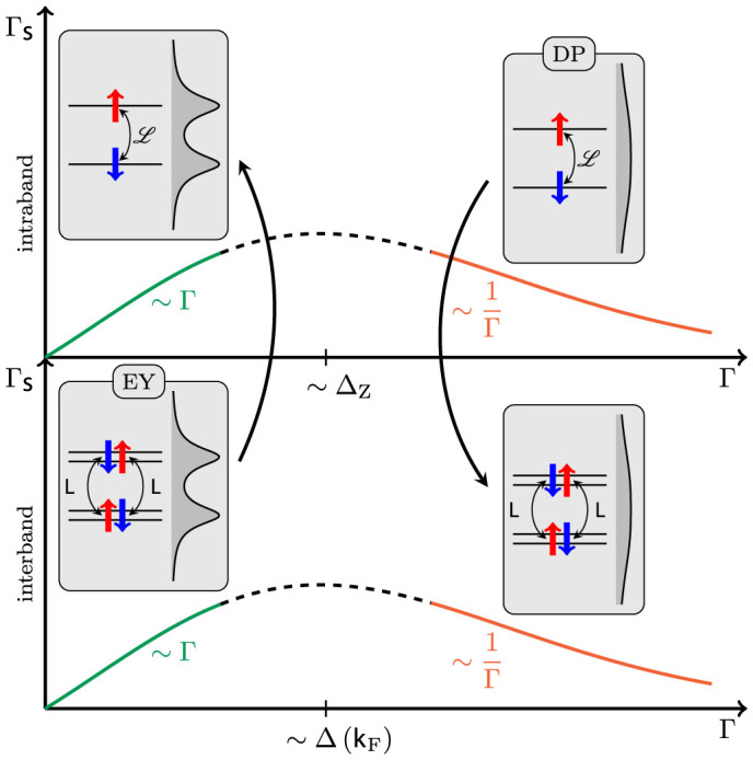
According to Eq. (15), the contributions from intra- ( ) and inter-band (L(kF)) processes are additive to lowest order in the SOC and have a surprisingly similar form. A competition is observed between lifetime induced broadening (due to Γ) and the energy separation between states (Δ(kF) or ΔZ). The situation, together with schematics of the corresponding band-structures, is shown in Fig. 3. When the broadening is much smaller than the energy separation, the relaxation is EY-like,
  , even when the intra-band SOC dominates, i.e. for a material with inversion symmetry breaking. This situation was also studied in Ref. 29, 30 and it may be realized in III-V semiconductors in high magnetic fields. For metals with inversion symmetry, this is the canonical EY regime.
Figure 3. Γs as a function of Γ according to Eq. (15) concerning separately the contributions due to intra- (upper) and inter-band (lower) SOC's.

The insets are schematics of the band-structure including the broadening due to Γ (double arrows indicate the matrix elements). The arrows indicate the equivalence of the different spin-relaxation regimes. The conventional DP and EY scenarios are those in the top-right and bottom-left corners, respectively.
When the states are broadened beyond distinguishability (i.e.  or ΔZ), spin-relaxation is caused by two quasi-degenerate states and the relaxation is of DP-type,
  , even for a metal with inversion symmetry,
  . For usual metals, the
  , criterion implies a breakdown of the quasi-particle picture as therein Δ(kF) is comparable to the bandwidth, thus this criterion means strong-localization. In contrast, metals with nearly degenerate bands remain metallic as e.g. MgB2 (Ref. 25) and the alkali fullerides (K3C60 and Rb3C60) (Ref. 26), which are strongly correlated metals with large Γ. When the intra-band SOC dominates, i.e. for a strong inversion symmetry breaking, this is the canonical DP regime. These observations provide the ultimate link between these two spin-relaxation mechanisms, which are conventionally thought as being mutually exclusive.
Similar behavior can be observed in other models (details are given in the Supplementary material),  and
and  remain valid in the two different limits but the intermediate behavior is not universal. A particularly compelling situation is the case of graphene where a four-fold degeneracy is present at the Dirac-point and both inter- and intra-band SOC are present thus changing the chemical potential would allow to map the crossovers predicted herein.
Methods
We consider Eq. (14) as a starting point. The Matsubara Green's function of  can be written as
 |
where
 |
is the Matsubara Green's function of fermionic field operators in band (α) and spin (s). The effect of  is taken into account by the finite momentum-scattering rate, Γ.
Using the relationship between the Green's function and spectral density, the Matsubara summation in Eq. (16) yields
 |
where
 |
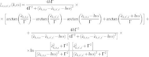
is the spectral density. By taking the imaginary part after analytical continuation, the energy integrals can be calculated at zero temperature. Then, by replacing momentum summation with integration, we obtain
 |
where
 |
and  , A is the area of the 2DEG. The matrix elements of the
  operator are
 |
We determine the expectation value of the z-component of electron spin following similar steps as
 |
where
 |
The matrix elements of the Sz operator are
 |
The spin-relaxation rate can be obtained as
 |
We note this is the sum of intra- and inter-band terms which are described separately.
Author Contributions
P.B. carried out all calculations under the guidance of B.D. A.K. contributed to the discussion and F.S. initiated the development of the unified theory. All authors contributed to the writing of the manuscript.
Supplementary Material
Supplementary file
Acknowledgments
We thank A. Pályi for enlightening discussions. Work supported by the ERC Grant Nr. ERC-259374-Sylo, the Hungarian Scientific Research Funds Nos. K101244, K105149, PD100373, and by the Marie Curie Grants PIRG-GA-2010-276834. BD acknowledges the Bolyai Program of the Hungarian Academy of Sciences.
References
- Wolf S. A. et al. Spintronics: A spin-based electronics vision for the future. Science 294, 1488–1495 (2001). [DOI] [PubMed] [Google Scholar]
- Žutić I., Fabian J. & Sarma S. D. Spintronics: Fundamentals and applications. Rev. Mod. Phys. 76, 323–410 (2004). [Google Scholar]
- Wu M. W., Jiang J. H. & Weng M. Q. Spin dynamics in semiconductors. Phys. Rep. 493, 61–236 (2010). [Google Scholar]
- Feher G. & Kip A. F. Electron Spin Resonance Absorption in Metals. I. Experimental. Physical Review 98, 337–348 (1955). [Google Scholar]
- Johnson M. & Silsbee R. H. Coupling of electronic charge and spin at a ferromagnetic-paramagnetic metal interface. Phys. Rev. B 37, 5312–5325 (1988). [DOI] [PubMed] [Google Scholar]
- Jedema F., Heersche H., Filip A., Baselmans J. & van Wees B. Electrical detection of spin precession in a metallic mesoscopic spin valve. Nature 416, 713–716 (2002). [DOI] [PubMed] [Google Scholar]
- Huertas-Hernando D., Guinea F. & Brataas A. Spin-orbit coupling in curved graphene, fullerenes, nanotubes, and nanotube caps. Phys. Rev. B 74, 155426 (2006). [Google Scholar]
- Ertler C., Konschuh S., Gmitra M. & Fabian J. Electron spin relaxation in graphene: the role of the substrate. Phys. Rev. B 80, 041405 (2009). [Google Scholar]
- Gmitra M., Konschuh S., Ertler C., Ambrosch-Draxl C. & Fabian J. Band-structure topologies of graphene: spin-orbit coupling effects from first principles. Phys. Rev. B 80, 235431 (2009). [Google Scholar]
- Castro Neto A. H. & Guinea F. Impurity-induced spin-orbit coupling in graphene. Phys. Rev. Lett. 103, 026804 (2009). [DOI] [PubMed] [Google Scholar]
- Dóra B., Murányi F. & Simon F. Electron spin dynamics and electron spin resonance in graphene. Eur. Phys. Lett. 92, 17002 (2010). [Google Scholar]
- Zhang P. & Wu M. W. Electron spin relaxation in graphene with random Rashba field: comparison of the D'yakonov-Perel' and Elliott-Yafet-like mechanisms. New J. Phys. 14, 033015 (2012). [Google Scholar]
- Ochoa H., Castro Neto A. H. & Guinea F. Elliot-yafet mechanism in graphene. Phys. Rev. Lett. 108, 206808 (2012). [DOI] [PubMed] [Google Scholar]
- Tombros N., Józsa C., Popinciuc M., Jonkman H. T. & van Wees B. J. Electronic spin transport and spin precession in single graphene layers at room temperature. Nature 448, 571–574 (2007). [DOI] [PubMed] [Google Scholar]
- Han W. et al. Tunneling Spin Injection into Single Layer Graphene. Phys. Rev. Lett. 105, 167202 (2010). [DOI] [PubMed] [Google Scholar]
- Han W. & Kawakami R. K. Spin relaxation in single-layer and bilayer graphene. Phys. Rev. Lett. 107, 047207 (2011). [DOI] [PubMed] [Google Scholar]
- Yang T.-Y. et al. Observation of long spin-relaxation times in bilayer graphene at room temperature. Phys. Rev. Lett. 107, 047206 (2011). [DOI] [PubMed] [Google Scholar]
- Pikus G. E. & Titkov A. N. In Meier F., & Zakharchenya B. (eds.) Optical Orientation (North-Holland, Amsterdam, 1984). [Google Scholar]
- Averkiev N., Golub L. & Willander M. Spin relaxation anisotropy in two-dimensional semiconductor systems. J. Phys. Cond. Mat. 14, R271–R283 (2002). [Google Scholar]
- Glazov M. M., Sherman E. Y. & Dugaev V. K. Two-dimensional electron gas with spin-orbit coupling disorder. Phys. E 42, 2157–2177 (2010). [Google Scholar]
- Elliott R. J. Theory of the Effect of Spin-Orbit Coupling on Magnetic Resonance in Some Semiconductors. Phys. Rev. 96, 266–279 (1954). [Google Scholar]
- Yafet Y. Conduction electron spin relaxation in the superconducting state. Physics Letters A 98, 287–290 (1983). [Google Scholar]
- Dyakonov M. & Perel V. Spin relaxation of conduction electrons in noncentrosymmetric semiconductors. Soviet Physics Solid State, USSR 13, 3023–3026 (1972). [Google Scholar]
- Tombros N. et al. Anisotropic spin relaxation in graphene. Phys. Rev. Lett. 101, 046601-1–4 (2008). [DOI] [PubMed] [Google Scholar]
- Simon F. et al. Generalized Elliott-Yafet Theory of Electron Spin Relaxation in Metals: Origin of the Anomalous Electron Spin Lifetime in MgB2. Phys. Rev. Lett. 101, 177003-1–4 (2008). [DOI] [PubMed] [Google Scholar]
- Dóra B. & Simon F. Electron-spin dynamics in strongly correlated metals. Phys. Rev. Lett. 102, 137001 (2009). [DOI] [PubMed] [Google Scholar]
- Mori H. & Kawasaki K. Antiferromagnetic resonance absorption. Progress of Theoretical Physics 28, 971–987 (1962). [Google Scholar]
-
Oshikawa M. & Affleck I.
Electron spin resonance in
 antiferromagnetic chains. Phys. Rev. B
65, 134410 (2002). [Google Scholar]
 - Ivchenko E. L. Spin relaxation of free carriers in a noncentrosymmetric semiconductor in a longitudinal magnetic field. Sov. Phys. Solid State 15, 1048 (1973). [Google Scholar]
- Burkov A. A. & Balents L. Spin relaxation in a two-dimensional electron gas in a perpendicular magnetic field. Phys. Rev. B 69, 245312 (2004). [Google Scholar]
Associated Data
This section collects any data citations, data availability statements, or supplementary materials included in this article.
Supplementary Materials
Supplementary file


