

Abstract
Deformable registration has been widely used in neuroscience studies for spatial normalization of brain images onto the standard space. Because of possible large anatomical differences across different individual brains, registration performance could be limited when trying to estimate a single directed deformation pathway, i.e., either from template to subject or from subject to template. Symmetric image registration, however, offers an effective way to simultaneously deform template and subject images toward each other until they meet at the middle point. Although some intensity‐based registration algorithms have nicely incorporated this concept of symmetric deformation, the pointwise intensity matching between two images may not necessarily imply the matching of correct anatomical correspondences. Based on HAMMER registration algorithm (Shen and Davatzikos, [2002]: IEEE Trans Med Imaging 21:1421–1439), we integrate the strategies of hierarchical attribute matching and symmetric diffeomorphic deformation to build a new symmetric‐diffeomorphic HAMMER registration algorithm, called as S‐HAMMER. The performance of S‐HAMMER has been extensively compared with 14 state‐of‐the‐art nonrigid registration algorithms evaluated in (Klein et al., [2009]: NeuroImage 46:786–802) by using real brain images in LPBA40, IBSR18, CUMC12, and MGH10 datasets. In addition, the registration performance of S‐HAMMER, by comparison with other methods, is also demonstrated on both elderly MR brain images (>70 years old) and the simulated brain images with ground‐truth deformation fields. In all experiments, our proposed method achieves the best registration performance over all other registration methods, indicating the high applicability of our method in future neuroscience and clinical applications. Hum Brain Mapp 35:1044–1060, 2014. © 2013 Wiley Periodicals, Inc.
Keywords: symmetric registration, anatomical correspondence, hierarchical attribute matching, diffeomorphism, HAMMER
INTRODUCTION
Modern medical imaging technology provides a safe way to perform clinical diagnosis and research, such as human brain development, aging and disease‐related anomalies. To measure the subtle anatomical difference, accurate deformable registration plays an important role in dealing with confounding intrasubject changes in longitudinal studies and intersubject variability in cross‐sectional studies.
A lot of deformable image registration methods have been proposed in the last decades. A comprehensive survey can be found in [Crum et al., 2004; Maintz and Viergever, 1998; Woods et al., 1998a; Woods et al., 1998b; Zitová and Flusser, 2003]. In general, the goal of deformable registration is to estimate the dense deformation field from template (target image) to subject (source image) by maximizing a certain image similarity measurement between warped subject and template images. As a highly ill‐posed problem, regularization on the deformation field is imposed to guarantee that the deformation field is practically reasonable.
All registration methods can be roughly classified into two categories: intensity‐based registration and feature‐based registration. Most registration methods fall into the first category [Andersson et al., 2008; Ardekani et al., 2005; Ashburner, 2007; Avants et al., 2011; Beg et al., 2005; Cachier et al., 2003; Christensen, 1999; Hernandez et al., 2009; Rueckert et al., 1999; Thirion, 1998; Vercauteren et al., 2009]. One of the most popular registration algorithm in this category is Demons algorithm [Thirion, 1998], which aims to maximize the intensity similarity between two images. Several gradient‐based optimization methods [Klein et al., 2010; Pennec et al., 1998] have been proposed to iteratively refine the deformation field in the Demons algorithm. However, a major limitation in these intensity‐based registration methods is that the intensity matching does not necessarily mean the matching of correct anatomical correspondences. Typical example is that the intensity changes are not sufficient to distinguish the real tissue characteristics from those arising from image artifact or noise [Crum et al., 2003].
On the other hand, feature‐based registration methods [Davatzikos, 2001; Liu et al., 2004; Shen and Davatzikos, 2002; Shen and Davatzikos, 2003] formulate the image registration as a feature matching and deformation optimization problem. For example, HAMMER [Shen and Davatzikos, 2002; Shen and Davatzikos, 2003] uses an attribute vector as the morphological signature of each point to reduce the ambiguity in correspondence detection during the image registration procedure. Specifically, each attribute vector includes image intensity, edge type (i.e., nonedge and six combinations of edges between white matter, grey matter, and cerebrospinal fluid), and a number of rotation‐invariant geometric moment invariants calculated in multiple neighborhood scales to reflect the underlying anatomy around each point at multiple resolutions. To further avoid the ambiguities during the correspondence detection, hierarchical matching strategy is also developed in HAMMER by allowing the driving voxels (with distinctive attribute vectors) to steer the entire deformation field in the initial registration stages. Besides, several improved variants of HAMMER [Shen, 2007, 2009; Wu et al., 2010; Wu et al., 2006, Xue et al., 2006] have been proposed in the past, and applied successfully to many large clinical studies and trials, with software (HAMMER suite) freely available at NITRC (http://www.nitrc.org/projects/hammerwml) and http://www.hammersuite.com/, respectively.
Recently, 14 deformable registration methods have been comprehensively evaluated on human brain MR images in [Klein et al., 2009]. It is worth noting that all these 14 nonrigid registration methods are intensity‐based, which may not be able to provide sufficient anatomical information for establishing reasonable correspondence between images under registration [Crum et al., 2003]. Meanwhile, we also notice that SyN [Avants et al., 2006; Avants et al., 2008] innovatively estimates the symmetrical deformation pathway from two ends (template and subject) to the middle point, and thus achieves the overall best performance among all 14 registration methods [Klein et al., 2009]. Inspired by this novel symmetric registration mechanism [Avants et al., 2008; Vercauteren et al., 2008], we propose here a feature‐based symmetric registration method to overcome the limitation of intensity‐based registration methods and also take the advantage of symmetric registration mechanism. Specifically, the contribution of our feature‐based registration method is at threefolds. First, we develop a new attribute vector definition and key point selection method for image registration. The attribute vector on each voxel considers not only local image appearance but also edge information. The key points are hierarchically selected during the registration by a new nonuniform sampling strategy, which ensures that most key points be selected from distinctive regions and also cover the whole brain. Second, robust correspondence matching (by comparing attribute vectors) is performed in a symmetric way. In particular, we simultaneously optimize the deformations on key points from template to subject and also from subject to template, until these two images are close enough to the middle point of the whole deformation pathway. Because the correspondence matching is always performed between the key points on the deformed template and the deformed subject, it is relatively easier, compared with the case of directly finding correspondences between the original template and the original subject. Accordingly, our method is able to handle large anatomical variations among individual brains. Third, we adapt the registration procedure to a space of diffeomorphic transformation by following the efficient approach proposed in [Vercauteren et al., 2009]. Therefore, the estimated deformation field by our registration method is smooth and invertible, but the computation time can be significantly saved, compared with other complicated diffeomorphic registration methods [Avants et al., 2011; Beg et al., 2005].
To demonstrate the registration performance of our proposed method, we compare it with the 14 state‐of‐the‐art nonrigid registration methods evaluated in [Klein et al., 2009] using the same four datasets, LBPA40 [Shattuck et al., 2008], IBSR18 (http://www.cma.mgh.harvard.edu/ibsr/), CUMC12, and MGH10 datasets. Because none of the these four datasets include the elderly brain images, we further demonstrate the registration performance on 18 elderly brains (>70 years old), with the comparison to the top ranked SyN [Avants et al., 2008] and the widely used diffeomorphic Demons [Vercauteren et al., 2009] methods. In all experiments, our proposed method (S‐HAMMER) achieves the best registration performance.
The article is organized as follows. In Section “Methods,” we formulate our registration problem and provide a solution in the form of symmetric deformation. Experimental results are provided in Section “Experiments” to demonstrate the performance of our proposed method. Section “Conclusion” concludes this article.
METHODS
In general, the deformable registration seeks to find a deformation , where displacement defines the mapping of the point from template T to the domain of subject S, . In this section, we will first present the overview of our registration method in Section “Overview of Our Symmetric Feature‐Based Registration Method.” The energy function and its respective solution will be provided in Section “Attribute Vector, Key Points, and Energy Function” and Section “Solution to the Energy Function,” respectively. A summary of our proposed registration method will be given in the end of this section (Section “Summary”).
Overview of Our Symmetric Feature‐Based Registration Method
Top of Figure 1 provides the overview of our feature‐based symmetric registration method. As we can see from this figure, instead of directly estimating the deformation field from template to subject, we depart from both template and subject simultaneously. Thus, we can obtain two deformation fields, from template space (denoted by red arrow) and from the subject (denoted by blue arrow). Both and point toward the common space. In the end, the deformation field from template to subject can be calculated by , where denotes the composition of two deformation fields. On the other hand, the inverse deformation field from subject to template can be also obtained by . Examples of and its inverse are shown in the figure for better understanding.
Figure 1.
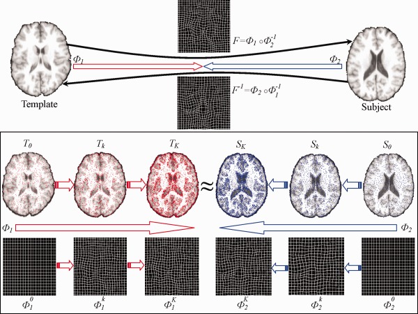
The framework of our proposed S‐HAMMER registration method. Both template and subject images deform from their own spaces by following the respective deformations and , until they become similar to each other in the middle point of the whole deformation pathway. The estimations of and are steered by robust attribute matching on key points between the gradually warped template (overlaid with red points) and subject (overlaid with blue points). (Note that the number of key points increases with the progress of registration.) After that, the whole deformation field From template to subject can be obtained by compositing and the inversed , i.e., ° . At the same time, the inverse deformation field from subject to template can also be obtained by ° . [Color figure can be viewed in the online issue, which is available at http://wileyonlinelibrary.com.]
As mentioned early, anatomical correspondence is very important in deformable image registration. Therefore, attribute vector is defined on each voxel to establish the correspondence. To further improve the correspondence detection, we acquire a set of key points and estimate the deformation by only considering these key points with distinctive features. As shown in the bottom of Figure 1, only a small number of critical points are selected as the key points (denoted in red for template and blue for subject, respectively) to drive the image registration. Since and are iteratively estimated during registration, we use to denote the iteration in the following text. Thus, in the beginning of registration , and , along with the identity deformation pathway and . With the progress of registration, the template image gradually deforms to by that is estimated in the iteration. Similarly, the subject image deforms to by following the respective estimated deformation . In the meantime, more voxels are selected as key points to refine the deformation pathways and w.r.t. and , as shown in the bottom of Figure 1, which is repeated until the deformed template image and the deformed subject image become very similar in the end of registration . The energy function describing this hierarchical symmetric registration procedure is described next.
Attribute Vector, Key Points, and Energy Function
Attribute vector
Attribute vector is considered as the morphological signature to identify each voxel. Although some rich image descriptors, e.g., SIFT [Lowe, 2004] and SURF [Bay et al., 2008], work well on correspondence matching, they are computational expensive and sensitive to the structural changes across different brain images. Local histogram‐based feature is used in [Shen, 2007]; however, only local image appearance information is utilized. For robust correspondence matching for a specific voxel, we incorporate both local image appearance (i.e., image intensities) and edge information (i.e., gradients) in its neighborhood (with radius ), into the attribute vector . Then, normalized cross‐correlation is used to evaluate the similarity between point in the deformed template and point in the deformed subject , which is denoted as . We further define the feature discrepancy as , which ranges from 0 to 1. It is worth noting that the negative correlation is possible, which indicates the two attribute vectors (after normalization) are negatively correlated. In all our experiments, is set to three pixels (i.e., 3 mm in the original image with 1 mm voxel size). Apparently, the similarity between points and is evaluated by their respective subvolumes, not their individual voxels. To further improve the efficiency and robustness of our method, we hierarchically select key points, as detailed below, and let them drive the estimation of entire deformation pathways and , respectively.
Key point selection
There are two criteria for selecting key points: (1) in a local view, key points should locate at distinctive regions in the brain image, such as sulcal root, gyral crown, and ventricular boundary, since they are relatively easy to identify their correspondences; (2) in a global view, key points should cover the entire brain image (i.e., with key points distributed in all brain regions) to derive the whole brain deformation, while the density of key points should be low in uniform regions and high in context‐rich regions.
To meet these criteria, we use the importance sampling strategy [Wang et al., 2010] to hierarchically select key points. Specifically, we smooth and normalize the gradient magnitude values over the whole image domain of subject and template, respectively. Then, we use the obtained values as the importance (or probability) of each voxel to be selected as a key point during the registration procedure. Note that, although more sophisticated method [Kadir and Brady, 2001] could be used here for guiding key point selection, we use a simple gradient guided strategy since it is computationally fast. Based on this importance (probability) map, a set of key points can be sampled via Monte Carlo simulation. Figure 2 shows the nonuniform sampling based on the importance (probability) map (Fig. 2a). The initial set of key points is displayed in red and the key points added in the later stages of registration are displayed in blue and green in Figure 2b, respectively. It can be observed from Figure 2 that the key points are more concentrated at context‐rich (or edge‐rich) regions, where the values of importance (or probability) are high.
Figure 2.
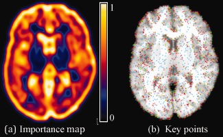
Nonuniform sampling of key points using the importance (probability) map (a). Key points are hierarchically selected and added at different stages of registration, as displayed by blue, green, and red points in (b), respectively. [Color figure can be viewed in the online issue, which is available at http://wileyonlinelibrary.com.]
After applying the above‐proposed nonuniform sampling to both warped template and warped subject , we can obtain the template key points and the subject key points at the iteration of registration. Here, and are the numbers of key points in the warped template and the warped subject in the iteration, respectively.
Robust correspondence detection by soft assignment
In the end of the iteration, suppose we have obtained the deformation pathway (from to ) and (from to ). Then, in the iteration, we will continue to estimate the incremental deformations from to and from to . As we will explain later, the refined deformation fields and in the end of the iteration can be obtained by integrating the incremental deformation fields and , respectively.
Figure 3 demonstrates the procedure of correspondence detection on a particular template key point of the tentatively deformed template (black triangle), given the tentatively estimated incremental deformation . Specifically, exhaustive search is performed to refine the correspondence w.r.t. each candidate point (pink triangle) within a search neighborhood (blue dashed circle), according to the two criteria: (1) the feature discrepancy, i.e., , should be as small as possible between and ; (2) the spatial distance between candidate point and the tentatively estimated location , i.e., , should be as close as possible.
Figure 3.
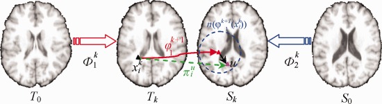
Schematic explanation of correspondence detection procedure between T k and S k in our registration method. For a particular template key point (black triangle), exhaustive search is performed in a searching neighborhood (blue dash circle) based on the tentatively estimated incremental deformation from T k to S k. Each candidate u (pink triangle) in the searching neighborhood has the probability to indicate the likelihood of being the true correspondence, which is related with the feature discrepancy and the spatial distance . [Color figure can be viewed in the online issue, which is available at http://wileyonlinelibrary.com.]
Because there are a lot of uncertainties in correspondence matching, encouraging multiple correspondences is proven effective to alleviate the ambiguity issue [Chui and Rangarajan, 2003]. Specifically, for the underlying template key point , a probability (called as spatial assignment) is assigned to each candidate point during correspondence matching. Here, denotes for the search neighborhood during the feature matching. For robust correspondence matching, even the candidate points with high discrepancy are encouraged to contribute to the correspondence matching in the beginning of registration. As the registration progresses, only the candidates with similar attribute vectors are considered until only the exact one‐to‐one correspondence is detected in the end of registration for achieving the registration specificity. This dynamic procedure can be encoded with the entropy term on the probability, i.e., . Here, high entropy implies the fuzzy assignment, while low value indicates more specific correspondence matching. The refinement of incremental deformation field follows the same way as discussed above, except that we use to denote the assignment of each candidate point in the search neighborhood . We use a scalar to enforce the dynamic evolution on correspondence assignment, as shown in the energy function below.
Energy function
The total energy function in estimating the incremental deformation fields and is given as:
| (1) |
where measures the bending energy of incremental deformation fields and [Bookstein, 1989]. in Eq. (1) is a parameter for controlling the impact of smoothness of the incremental deformation fields.
Apparently, the energy function has three terms. The first and second terms are symmetric, describing costs during the correspondence matching which is performed on the key points of the deformed template and the deformed subject , respectively. The fuzziness of multiple correspondences is controlled by the entropy term. As the temperature decreases as registration progresses, the impact of the entropy terms to the overall energy in Eq. (1) drops gradually, thus effectively encouraging multiple correspondences in the early stage of registration and one‐to‐one correspondence in the end of registration. The last term in Eq. (1) is used as the regularization term to enforce the smoothness of incremental deformations.
Solution to the Energy Function
First, the spatial assignment can be calculated by minimizing in Eq. (1) w.r.t. :
| (2) |
Similarly, the spatial assignment can be obtained as:
| (3) |
It is clear that spatial assignments and are penalized by (1) the discrepancy degree and (2) the magnitude of the incremental deformation. Notice that the temperature is the denominator of the exponential function in Eqs. (2) and (3). Therefore, when is very high in the beginning of registration, even though the discrepancy might be large or the candidate locations might be faraway, those points might still be considered as candidate correspondence. As registration progresses, the specificity of correspondence will be encouraged by gradually decreasing the temperature until only the closest candidate point with the smallest discrepancy is selected as the candidate correspondence in the end of registration.
After obtaining for each candidate , the estimated incremental deformation on key point can be computed by optimizing the energy function in Eq. (1) w.r.t. :
| (4) |
Similarly, the incremental deformation of each can be updated as:
| (5) |
The estimated incremental deformation fields and are sparsely associated with selected key points. Then, thin‐plate spline (TPS) [Bookstein, 1989] can be used to interpolate the dense deformation fields and with the bending energy minimized. To ensure the invertibility of the final deformation fields, we follow an efficient nonparametric diffeomorphic approach (Vercauteren et al., 2009] to adapt the optimization of and to the space of diffeomorphic transformation. In particular, we consider the incremental deformation fields and in the vector space of velocity fields and then map them to the space of diffeomorphism through the exponentials, i.e., or .
Specifically, the following steps will be applied to calculate the deformation pathway : (1) compute the exponential of incremental deformation field by the scaling and squaring method [Vercauteren et al., 2009]; (2) compose the exponential with the previously estimated deformation field by ; (3) the inverse deformation field can be computed by . Similarly, the deformation pathway and its inverse can be computed by following the same above three steps.
Finally, the latest estimated deformation pathways and will be used to deform the original template and subject images, respectively, and obtain the deformed template and deformed subject for the next iteration of registration. The whole registration procedure will be iteratively repeated until the deformed template and deformed subject images meet at the middle point.
Summary
Our registration method is briefly summarized below:
Set , , . as identity transformation, and .
Obtain the deformed template and the deformed subject image by deforming the original template image w.r.t. and the original subject image w.r.t. . Update the calculation of attribute vectors on and , respectively.
Select the key points and for the deformed template and the deformed subject by nonuniform importance sampling;
Determine the incremental deformation for each by Eq. (2) and Eq. (4), based on correspondence matching from to .
Determine the incremental deformation for each by Eq. (3) and Eq. (5), based on the correspondence matching from to .
Interpolate the dense incremental deformation field with TPS by considering as the source point set and as the target point set.
Interpolate the dense incremental deformation field with TPS by considering as the source point set and as the target point set.
Compute the exponential map and by the scaling and squaring method, respectively.
Compute the deformation pathways for both directions by and .
Compute the inverse deformation pathways for both directions by and .
Se .
If , go to step 2 to include more key points in registration. Otherwise, compute the final deformation field from template to subject as , and its inverse deformation field as . (Refer to Fig. 1 for better interpretation.)
EXPERIMENTS
To evaluate the registration performance, we test our proposed S‐HAMMER registration method on LPBA40, IBSR18, CUMC12, and MGH10 datasets by comparing it with 14 state‐of‐the‐art nonrigid registration methods evaluated in [Klein et al., 2009]. Because these dataset only involve the young brains, we further evaluate the registration performance on 18 elderly MR brain images (>70 years old), with the comparison to SyN and diffeomorphic Demons registration. Finally, we also evaluate the registration accuracy of our proposed method using the simulated brain images, by comparing with all our previously developed registration methods [Shen, 2004, 2007; Shen and Davatzikos, 2002; Wu et al., 2010], which are all freely available in our stand‐alone software ‘HAMMER‐Suite’ (http://www.hammersuite.com/). The overlap ratios on LPBA40, IBSR18, CUMC12, and MGH10 by 14 state‐of‐the‐art methods are provided by courtesy from Dr. Arno Klein (the corresponding author of [Klein et al., 2009]), which can be downloaded at http://www.mindboggle.info/papers/evaluation_NeuroImage2009.php.
Experiments on LPBA40, IBSR18, CUMC12, and MGH10 Datasets
In this section, similar to [Klein et al., 2009], we comprehensively evaluate the registration performance of our S‐HAMMER method on the 4 datasets (LPBA40, IBSR18, CUMC12, MGH10), which are downloaded from http://www.mindboggle.info/papers/evaluation_NeuroImage2009.php, and further compare with all 14 registration methods evaluated in [Klein et al., 2009]. Since the target overlap ratio is used in [Klein et al., 2009] to evaluate those 14 registration methods, we also use the same measurement in this article, which is defined as:
| (6) |
where and denote the ‐th ROI in the target image (i.e., template) and source image (i.e., the warped subject), respectively.
LPBA40 dataset
In this experiment, we apply S‐HAMMER on the LPBA40 dataset [Shattuck et al., 2008] which has 40 brain images, each with 56 manually‐labeled ROIs. This dataset is provided by the Laboratory of Neuro Imaging (LONI) at UCLA (http://www.loni.ucla.edu/Atlases/LPBA40). Following [Klein et al., 2009], we performed registrations for totally possible pairs of template and subject images for each registration method under comparison.
In Figure 4, we provide the mean and standard deviation of target overlap ratios for FLIRT (linear registration method), 14 nonlinear registration methods evaluated in [Klein et al., 2009], and our S‐HAMMER registration method. From the mean and standard deviations also shown in Table 1, it can observed that our S‐HAMMER (72.48 ± 8.46%) is ranked top over all registration methods, followed by ART (71.85 ± 9.59%), SyN (71.46 ± 10.86%), FNIRT (70.07 ± 9.80%), and JRD‐fluid (70.02 ± 9.83%).
Figure 4.
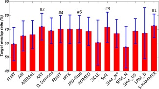
The respective mean and standard deviation of target overlap ratios of 56 ROIs on LPBA40 dataset by FLIRT, 14 nonlinear registration methods evaluated in (Klein et al., 2009), and our S‐HAMMER registration method. S‐HAMMER is ranked top, followed by ART (#2), SyN (#3), FNIRT (#4), and JRD‐fluid (#5). The detailed numbers are provided in Table 1. [Color figure can be viewed in the online issue, which is available at http://wileyonlinelibrary.com.]
Table 1.
The mean and standard deviation of target overlap ratios (in %) for FLIRT (linear registration method), 14 nonlinear registration methods, and our S‐HAMMER registration method on LBPA40, IBSR18, CUMC12, and MGH10 dataset
| Method | LPBA40 | IBSR18 | CUMC12 | MGH10 |
|---|---|---|---|---|
| FLIRT | 59.29 ± 11.94 | 39.71 ± 13.00 | 39.63 ± 11.51 | 46.24 ± 14.03 |
| AIR | 65.23 ± 10.72 | 41.41 ± 13.35 | 42.52 ± 11.90 | 47.99 ± 14.10 |
| ANIMAL | 66.20 ± 10.17 | 46.31 ± 13.51 | 42.78 ± 11.95 | 50.40 ± 15.21 |
| ART | 71.85 ± 9.59 | 51.54 ± 14.42 | 50.54 ± 12.16 | 56.10 ± 15.33 |
| D. Demons | 68.93 ± 9.23 | 46.83 ± 13.37 | 46.45 ± 11.46 | 52.28 ± 14.94 |
| FNIRT | 70.07 ± 9.80 | 47.63 ± 14.15 | 46.53 ± 12.26 | 49.54 ± 14.58 |
| IRTK | 70.02 ± 10.26 | 52.09 ± 14.97 | 51.75±12.45 | 54.90 ± 15.70 |
| JRD‐fuild | 70.02 ± 9.83 | 48.95 ± 13.87 | 46.37 ± 12.06 | 52.33 ± 14.81 |
| ROMEO | 68.49 ± 10.12 | 46.48 ± 13.91 | 44.49 ± 13.04 | 51.23 ± 14.55 |
| SICLE | 60.41 ± 16.21 | 44.53 ± 13.03 | 42.08 ± 12.19 | 48.36 ± 14.31 |
| SyN | 71.46 ± 10.86 | 52.81 ± 14.85 | 51.63 ± 12.60 | 56.83 ± 15.81 |
| SPM_N*a | 66.97 ± 10.14 | 42.10 ± 13.25 | 36.70 ± 12.43 | 49.77 ± 14.54 |
| SPM_Nb | 57.13 ± 14.95 | 37.18 ± 14.11 | 42.93 ± 11.75 | 43.16 ± 15.88 |
| SPM_USc | 68.62 ± 9.00 | 45.29 ± 12.60 | 44.81 ± 11.35 | 49.61 ± 14.08 |
| SPM_Dd | 67.15 ± 18.34 | 54.02 ± 14.70 | 51.98 ± 13.91 | 54.31 ± 16.05 |
| S‐HAMMER | 72.48 ± 8.46 | 55.47 ± 11.27 | 53.74 ± 9.82 | 58.20 ± 15.03 |
SPM 5 (“SPM2‐type” Normalization).
SPM 5 (Normalization).
SPM 5 (Unified Segmentation).
SPM 5 (DARTEL Toolbox).
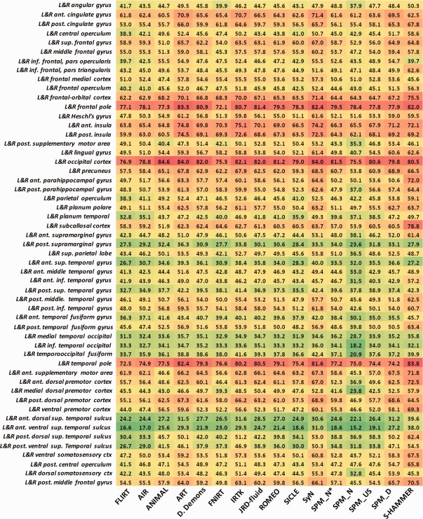
We further show the mean target overlap ratio of each of 56 ROIs by these 16 registration methods in Figure 5, with red and green colors denoting the high and low overlap ratios, respectively. It is clear that S‐HAMMER consistently performs well in all ROIs.
Figure 5.
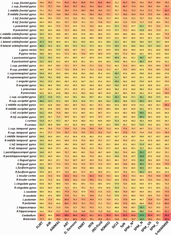
The target overlap ratios of each of 56 ROIs on LPBA40 dataset by the 16 registration methods. Results by S‐HAMMER are shown in the last column. [Color figure can be viewed in the online issue, which is available at http://wileyonlinelibrary.com.]
ISBR18 dataset
The detailed information about 18 brains images can be found through the Internet Brain Segmentation Repository (http://www.cma.mgh.harvard.edu/ibsr/ibsr_data/IBSRv2/) as IBSR v2.0. The T 1‐weighted images have been “positionally normalized” to the Talairach orientation. Also, all the data have been processed by “autoseg” bias field correction program developed in CMA (Center for Morphometric Analysis, Massachusetts General Hospital). Also, each brain has been manually labeled with 96 ROIs. Again, full combinations of pair‐wise registration are performed by each registration method.
The mean and standard deviation of target overlap ratios by FLIRT, 14 nonrigid registration methods in [Klein et al., 2009], and our S‐HAMMER registration method are shown in the third column of Table 1. It can be seen that S‐HAMMER achieves the highest average overlap ratio (55.47 ± 11.27%) over other 15 registration methods. The detailed target overlap ratio in 48 ROIs (left and right combined) by all registration methods are provided in Figure 6. Again, S‐HAMMER obtains the highest overlap ratios in most ROIs, except some small ones, which we will explain in Section “Experiments on Simulated Brain Images.”
Figure 6.
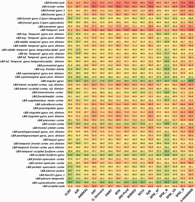
The target overlap ratios of 96 ROIs on IBSR18 dataset. The results by S‐HAMMER are shown in the last column. [Color figure can be viewed in the online issue, which is available at http://wileyonlinelibrary.com.]
The number of ROIs that each of 16 registration methods (FLIRT, 14 nonlinear registration methods in [Klein et al., 2009], and S‐HAMMER) wins over other methods in term of target overlap ratio is displayed in Figure 7. Specifically, S‐HAMMER achieves the best accuracy in 66 ROIs out of totally 96 ROIs. For the rest 30 ROIs, SPM_D wins in 19 ROIs, IRTK and SyN win in four different ROIs, ART wins in two ROIs, and JRD‐fluid wins in the last ROI.
Figure 7.
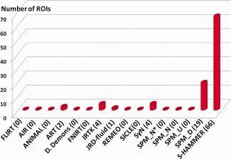
The number of ROIs that each of 16 registration methods wins over other methods in terms of target overlap ratio. Our S‐HAMMER wins the registration accuracy over all other methods in 66 ROIs, followed by SPM_D in 19 ROIs, IRTK in four ROIs, SyN in four ROIs, ART in two ROIs, and JRD‐fluid in one ROI. [Color figure can be viewed in the online issue, which is available at http://wileyonlinelibrary.com.]
CUMC12 dataset
Totally, 12 subjects in CUMC12 dataset were scanned at the Columbia University Medical Center by a 1.5T GE scanner. The images were resliced coronally to a slice thickness 3 mm. Then, the images were rotated to the cardinal orientation for manually labeling the whole brain to 130 ROIs. Again, all possible combinations of pair‐wise registration are performed for each of 16 registration methods under comparison.
The overall target ratio on 130 ROIs by FLIRT, 14 nonlinear registration methods, and S‐HAMMER are shown in the last second column of Table 1. S‐HAMMER achieves the highest measure (53.74 ± 9.82%) among all 16 registration methods, which is 3.4% improvement over the second top‐ranked registration method (SPM_D: 51.98 ± 14.70%). S‐HAMMER outperforms SPM_D in 86 ROIs among the total 130 ROIs. The detailed target overlap ratio in entire 130 ROIs by all registration methods are provided in Figure 8.
Figure 8.
The target overlap ratios of 130 ROIs on CUMC12 dataset. The results by S‐HAMMER are shown in the last column. [Color figure can be viewed in the online issue, which is available at http://wileyonlinelibrary.com.]
Specifically, the mean average target ratio on each ROI by S‐HAMMER and SPM_D is also shown in Figure 9, with red for S‐HAMMER and blue for SPM_D, respectively. For clear presentation, we show the mean overlap ratio for each pair of left‐right symmetric anatomical structure in Figure 9. We further perform paired t‐test in each ROI, where the significant improvement obtained by S‐HAMMER or SPM_D is shown by red or blue stars, respectively.
Figure 9.
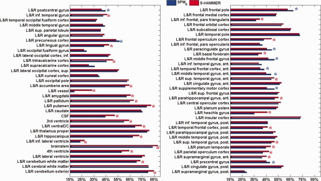
The target overlap ratios of 130 ROIs on CUMC12 dataset by S‐HAMMER (red) and SPM‐D (blue). To be clear, we display only the average target overlap ratio for each pair of left‐right symmetric ROIs. The red star denotes that S‐HAMMER has significant improvement over SPM‐D in particular ROI with t‐test (P < 0.05). The blue stars indicate that SPM_D has significant improvement over S‐HAMMER. [Color figure can be viewed in the online issue, which is available at http://wileyonlinelibrary.com.]
MGH10 dataset
A total of 10 subjects in MGH10 were scanned at the MGH/MIT/HMS Athinoula A. Martinos Center for Biomedical Imaging by a 3T Siemens scanner with standard head coil. The data have been performed with inhomogeneity correction procedure and further affine aligned to the MNI152 template. Each brain image was manually labeled into 106 ROIs. All possible pairwise registrations are performed.
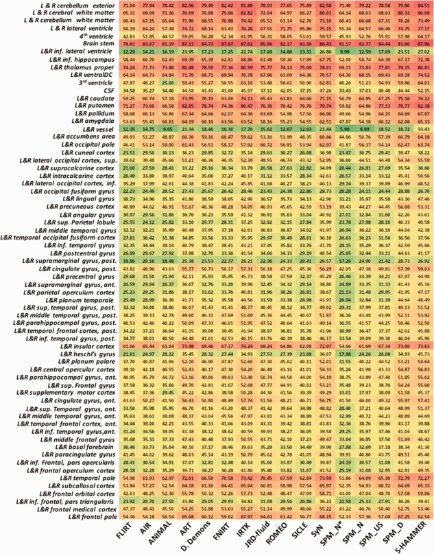
The mean and standard deviation of target overlap ratios by the 16 registration methods are shown in the last column of Table 1. The averaged target ratio in each ROI is displayed in Figure 10. In general, our S‐HAMMER registration achieves highest averaged target ratio of 58.2%, which leads 1.4% improvement over the 2nd ranked SyN registration method.
Figure 10.
The target overlap ratios of 106 ROIs on MGH10 dataset. The results by S‐HAMMER are shown in the last column. [Color figure can be viewed in the online issue, which is available at http://wileyonlinelibrary.com.]
Experiments on 18 Elderly Brains
In this experiment, MR brain images of 18 elderly subjects are used, each with image dimension of and voxel resolution of . After randomly selecting one subject as the template, we register all other 17 subjects onto the selected template by SyN, diffeomorphic Demons, and S‐HAMMER, respectively. SyN and diffeomorphic Demons are selected here for evaluation, since they are the top‐ranked and the popularly used methods among 14 nonlinear registration methods evaluated in [Klein et al., 2009]. The respective mean images (by averaging all registered images) via SyN, diffeomorphic Demos, and S‐HAMMER are shown in Figure 11a, c, and e, respectively.
Figure 11.
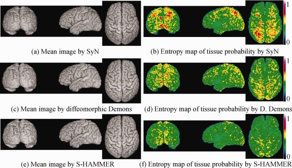
This figure demonstrates the registration performance on 18 elderly MR brain images. The mean images of all registered images by SyN, diffeomorphic Demons, and S‐HAMMER are shown in (a), (c), and (e), respectively. To examine the registration consistency across different subjects, the entropy of tissue probability map across all aligned subject images by SyN, diffeomorphic Demons, and S‐HAMMER are also provided in (b), (d), and (f), respectively, indicating that S‐HAMMER has the least variation across the aligned subject images. [Color figure can be viewed in the online issue, which is available at http://wileyonlinelibrary.com.]
Because the images have been segmented into gray matter (GM), white matter (WM), cerebral spinal fluid (CSF), and ventricle (VN), we can calculate the target overlap ratio for each tissue type, as shown in Table 2. The average target overlap ratio between template and each aligned subject is 70.10% for SyN, 70.88% for diffeomorphic Demons, and 74.13% for S‐HAMMER. For further quantifying registration consistency, we compute the entropy of tissue probability map across all aligned subjects voxel by voxel. Here, a high entropy value indicates less consistency. For S‐HAMMER, the average entropy value is 0.40, nearly 17% improvement compared to 0.48 obtained by diffeomorphic Demons, and 35% improvement compared to 0.62 obtained by SyN. The respective 3D map of entropy value is also shown in Figure 11b (by SyN), (d) (by diffeomorphic Demons), and (f) (by S‐HAMMER), respectively.
Table 2.
Target overlap ratio (in %) of white matter, gray matter, and ventricle on 18 elderly brains by SyN, diffeomorphic Demons, and S‐HAMMER
| White matter | Gray matter | Ventricle | Overall | |
|---|---|---|---|---|
| SyN | 71.28 ± 3.33 | 56.63 ± 3.58 | 82.40 ± 3.35 | 70.10 ± 3.42 |
| Diffeomorphic Demons | 72.05 ± 5.24 | 58.22 ± 8.00 | 82.36 ± 4.50 | 70.88 ± 6.34 |
| S‐HAMMER | 75.22 ± 3.22 | 62.36 ± 3.92 | 84.82 ± 1.86 | 74.13 ± 2.86 |
Experiments on Simulated Brain Images
Because our S‐HAMMER registration algorithm has integrated all the merits from our previously developed registration algorithms, we would like to evaluate its registration performance by comparison with all our previous registration algorithms, including (1) HAMMER [Shen and Davatzikos, 2002], (2) Intensity‐HAMMER [Shen, 2007], (3) Fast‐HAMMER [Shen, 2009], and (4) TPS‐HAMMER [Wu et al., 2010]. The respective features of all registration algorithms are listed in Table 3. Because these registration algorithms are all feature‐based methods, we also compare their registration performances with the top‐ranked intensity‐based registration method in [Klein et al., 2009], e.g., SyN [Avants et al., 2008].
Table 3.
Previously developed registration methods in our group

The simulated data are generated by the method presented in Xue et al. [Xue et al., 2006], where a statistical model is built from each wavelet sub‐band of sample deformation fields. In this experiment, 10 simulated brain images, as well as their ground‐truth deformations, are constructed by randomly sampling the deformation statistical model. These 10 simulated brain images have the dimension of and the resolution of . By warping the simulated brain images onto the template, we can quantify the registration accuracy for each registration algorithm by calculating the average error between the ground‐truth and the estimated deformation fields, voxel by voxel. The overall mean residual errors of the 10 simulated brain images are 0.78 mm by SyN, 0.71 mm by HAMMER, 0.80 mm by Intensity‐HAMMER, 1.01 mm by Fast‐HAMMER, 0.68 mm by TPS‐HAMMER, and 0.62 mm by S‐HAMMER, respectively. These results show that our S‐HAMMER achieves the lowest deformation residual errors, indicating the highest registration accuracy on the simulated data.
Discussion
We have evaluated our symmetric feature‐based registration method, called S‐HAMMER, on five datasets including both young and elderly brains. By extensive comparison with 14 nonlinear registration methods evaluated in [Klein et al., 2009], our S‐HAMMER registration method achieves best registration accuracy in terms of ROI overlap ratio, in all datasets. The computation time of S‐HAMMER on these five datasets is shown in Table 4, with comparison to SyN and diffeomorphic Demons. All experiments are performed on a Dell workstation (with 8 Xeon CPU@2.66GHz and 32G memory).4
Table 4.
The average computation time of each pairwise registration on five brain image datasets by SyN, diffeomorphic Demons, and S‐HAMMER (unit: minute)
| Algorithm | LPBA40 | IBSR18 | CUMC12 | MGH10 | Elderly brains |
|---|---|---|---|---|---|
| SyN | 30.2 | 28.3 | 29.1 | 29.5 | 32.5 |
| d. Demons | 1.9 | 2.3 | 2.1 | 1.4 | 2.8 |
| S‐HAMMER | 24.8 | 24.3 | 24.1 | 23.6 | 24.1 |
The deformation field in S‐HAMMER is largely steered by key points sampled in the hierarchical deformation mechanism. Since the small ROIs are confined with either poor image contrast or less image points, the number of key points may be not sufficient to drive the deformations of these small ROIs. Therefore, the performance gains of registration accuracy by our S‐HAMMER on small ROIs are not significant. Taking the left and right cuneal gyrus in IBSR18 dataset for example, the mean target ratio is 34.6% by S‐HAMMER, lower than 41.1% by SPM_D and 37.7% by SyN. However, this issue can be solved as follows. We assume the template image has the labeled image as well. Then, we can enforce the importance map of template image (shown in Fig. 2) at the particular ROIs to have very high degree, in order to sample enough key points at these ROIs. Finally, with this specific strategy, the average target ratio on left and right cuneal gyrus in IBSR18 dataset can reach as high as 42.6%.
CONCLUSIONS
In this article, we have presented a new feature‐based symmetric registration method, called S‐HAMMER, for MR brain images. Compared with intensity‐based registration methods, our method is able to establish more accurate anatomical correspondence by robust feature matching. Symmetric deformation mechanism is also utilized in our method to start the deformation estimation from both ends (template and subject) to the middle point of entire deformation pathway, which greatly alleviates the matching uncertainty during image registration.
Our symmetric feature‐based registration method has been comprehensively compared with 14 state‐of‐the‐art nonrigid registration methods (evaluated in [Klein et al., 2009]) using four real brain datasets with manually delineated ROIs and one dataset with 18 elderly brain MR images. Experimental results show that our S‐HAMMER registration method consistently produces the best registration results over all other methods under comparison. For better use of our method, S‐HAMMER has been successfully integrated into our stand‐alone image processing software “HAMMER Suite,” which can be freely downloaded at http://www.hammersuite.com/.
ACKNOWLEDGMENTS
The authors thank Dr. Arno Klein for his kind help on evaluating the registration performance. This work was supported in part by NIH grants EB006733, EB008374, EB009634 and AG041721.
REFERENCES
- Andersson J, Smith S, Jenkinson M (2008): FNIRT‐FMRIB's Non‐linear image registation tool. Fourteenth Annual Meeting of the Organization for Human Brain Mapping, Melbourne, Australia.
- Ardekani BA, Guckemus S, Bachman A, Hoptman MJ, Wojtaszek M, Nierenberg J (2005): Quantitative comparison of algorithms for inter‐subject registration of 3D volumetric brain MRI scans. J Neurosci Methods 142:67–76. [DOI] [PubMed] [Google Scholar]
- Ashburner J (2007): A fast diffeomorphic image registration algorithm. NeuroImage 38:95–113. [DOI] [PubMed] [Google Scholar]
- Avants B, Grossman M, Gee J (2006): Symmetric diffeomorphic image registration: Evaluating automated labeling of elderly and neurodegenerative cortex and frontal lobe. Third International Workshop on Biomedical Image Registration, Utrecht, The Netherlands, 50–57.
- Avants BB, Epstein CL, Grossman M, Gee JC (2008): Symmetric diffeomorphic image registration with cross‐correlation: Evaluating automated labeling of elderly and neurodegenerative brain. Med Image Anal 12:26–41. [DOI] [PMC free article] [PubMed] [Google Scholar]
- Avants BB, Tustison NJ, Song G, Cook PA, Klein A, Gee JC (2011): A reproducible evaluation of ANTs similarity metric performance in brain image registration. NeuroImage 54:2033–2044. [DOI] [PMC free article] [PubMed] [Google Scholar]
- Bay H, Ess A, Tuytelaars T, Gool LV (2008): SURF: Speeded up robust features. Comput Vis Image Understand 110:346–359. [Google Scholar]
- Beg F, Miller M, Trouve A, Younes L (2005): Computing large deformation metric mappings via geodesic flows of diffeomorphisms. Int J Comput Vis 61:139–157. [Google Scholar]
- Bookstein FL (1989): Principal warps: Thin‐plate splines and the decomposition of deformations. IEEE Trans Pattern Anal Mach Intell 11:567–585. [Google Scholar]
- Cachier P, Bardinet E, Dormont D, Pennec X, Ayache N (2003): Iconic feature based nonrigid registration: The PASHA algorithm. Comput Vis Image Understand 89:272–298. [Google Scholar]
- Christensen G (1999): Consistent linear‐elastic transformations for image matching. Visegrád, Hungary: Inform Process Med Imaging 224–237. [Google Scholar]
- Chui H, Rangarajan A (2003): A new point matching algorithm for non‐rigid registration. Comput Vis Image Understand 89:114–141. [Google Scholar]
- Crum WR, Griffin LD, Hill DLG, Hawkes DJ (2003): Zen and the art of medical image registration: Correspondence, homology, and quality. NeuroImage 20:1425–1437. [DOI] [PubMed] [Google Scholar]
- Crum WR, Hartkens T, Hill DLG (2004): Non‐rigid image registration: Theory and practice. Br J Radiol 77:S140–S153. [DOI] [PubMed] [Google Scholar]
- Davatzikos C (2001): Measuring biological shape using geometry‐based shape transformations. Image Vis Comput 19:63–74. [Google Scholar]
- Hernandez M, Bossa M, Olmos S (2009): Registration of anatomical images using paths of diffeomorphisms parameterized with stationary vector field flows. Int J Comput Vis 85:291–306. [Google Scholar]
- Kadir T, Brady M (2001): Saliency, scale and image description. Int J Comput Vis 45:83–105. [Google Scholar]
- Klein A, Andersson J, Ardekani BA, Ashburner J, Avants B, Chiang M‐C, Christensen GE, Collins DL, Gee J, Hellier P, Song JH, Jenkinson M, Lepage C, Rueckert D, Thompson P, Vercauteren T, Woods RP, Mann JJ, Parsey RV (2009): Evaluation of 14 nonlinear deformation algorithms applied to human brain MRI registration. NeuroImage 46:786–802. [DOI] [PMC free article] [PubMed] [Google Scholar]
- Klein S, Staring M, Murphy K, Viergever MA, Pluim JPW (2010): Elastix: A toolbox for intensity‐based medical image registration. IEEE Trans Med Imaging 29:196–205. [DOI] [PubMed] [Google Scholar]
- Liu T, Shen D, Davatzikos C (2004): Deformable registration of cortical structures via hybrid volumetric and surface warping. NeuroImage 21:1508–1517. [DOI] [PubMed] [Google Scholar]
- Lowe DG (2004): Distinctive image features from scale‐invariant keypoints. Int J Comput Vis 60:91–110. [Google Scholar]
- Maintz JBA, Viergever MA (1998): A survey of medical image registration. Med Image Anal 2:1–36. [DOI] [PubMed] [Google Scholar]
- Pennec X, Cachier P, Ayache N (1998): Understanding the “Demon's Algorithm”: 3D Non‐Rigid registration by Gradient Descent. 2nd Int. Conf. on Medical Image Computing and Computer‐Assisted Intervention, (MICCAI'99), LNCS 1679 Cambridge, UK.
- Rueckert D, Sonoda LI, Hayes C, Hill DLG, Leach MO, Hawkes DJ (1999): Nonrigid registration using free‐form deformations: Application to breast MR images. IEEE Trans Med Imaging 18:712–721. [DOI] [PubMed] [Google Scholar]
- Shattuck DW, Mirza M, Adisetiyo V, Hojatkashani C, Salamon G, Narr KL, Poldrack RA, Bilder RM, Toga AW (2008): Construction of a 3D probabilistic atlas of human cortical structures. NeuroImage 39:1064–1080. [DOI] [PMC free article] [PubMed] [Google Scholar]
- Shen D (2004): Image registration by hierarchical matching of local spatial intensity histograms In: Barillot C, Haynor DR, Hellier P, editors. Medical image computing and computer‐assisted intervention–MICCAI 2004. St. Malo, France: Springer‐Verlag GmbH; pp 582–590. [Google Scholar]
- Shen D (2007): Image registration by local histogram matching. Pattern Recognit 40:1161–1172. [Google Scholar]
- Shen D (2009): Fast image registration by hierarchical soft correspondence detection. Pattern Recognit 42:954–961. [DOI] [PMC free article] [PubMed] [Google Scholar]
- Shen D, Davatzikos C (2002): HAMMER: Hierarchical attribute matching mechanism for elastic registration. IEEE Trans Med Imaging 21:1421–1439. [DOI] [PubMed] [Google Scholar]
- Shen D, Davatzikos C (2003): Very high‐resolution morphometry using mass‐preserving deformations and HAMMER elastic registration. NeuroImage 18:28–41. [DOI] [PubMed] [Google Scholar]
- Thirion JP (1998): Image matching as a diffusion process: An analogy with Maxwell's demons. Med Image Anal 2:243–260. [DOI] [PubMed] [Google Scholar]
- Vercauteren T, Pennec X, Perchant A, Ayache N (2008): Symmetric log‐domain diffeomorphic registration: A demons‐based approach. New York, USA: Med Image Comput Comput‐Assist Interv 754–761. [DOI] [PubMed] [Google Scholar]
- Vercauteren T, Pennec X, Perchant A, Ayache N (2009): Diffeomorphic demons: Efficient non‐parametric image registration. NeuroImage 45:S61–S72. [DOI] [PubMed] [Google Scholar]
- Wang Q, Wu G, Yap P‐T, Shen D (2010): Attribute vector guided groupwise registration. NeuroImage 50:1485–1496. [DOI] [PMC free article] [PubMed] [Google Scholar]
- Woods RP, Grafton ST, Holmes CJ, Cherry SR, Mazziotta JC (1998a). Automated image registration. I. General methods and intrasubject, intramodality validation. J Comput Assist Tomogr 22:139–152. [DOI] [PubMed] [Google Scholar]
- Woods RP, Grafton ST, Watson JDG, Sicotte NL, Mazziotta JC (1998b). Automated image registration. II. Intersubject validation of linear and nonlinear models. J Comput Assist Tomogr 22:153–165. [DOI] [PubMed] [Google Scholar]
- Wu G, Yap P‐T, Kim M, Shen D (2010): TPS‐HAMMER: Improving HAMMER registration algorithm by soft correspondence matching and thin‐plate splines based deformation interpolation. NeuroImage 49:2225–2233. [DOI] [PMC free article] [PubMed] [Google Scholar]
- Wu G, Qi F, Shen D (2006): Learning‐Based Deformable Registration of MR Brain Images IEEE Transactions on Medical Imaging 25:1145–1157. [DOI] [PubMed] [Google Scholar]
- Xue Z, Shen D, Davatzikos C (2006): CLASSIC: Consistent Longitudinal Alignment and Segmentation for Serial Image Computing. NeuroImage 30:388–399. [DOI] [PubMed] [Google Scholar]
- Xue Z, Shen D, Karacali B, Stern J, Rottenberg D, Davatzikos C (2006): Simulating deformations of MR brain images for validation of atlas‐based segmentation and registration algorithms. NeuroImage 33:855–866. [DOI] [PMC free article] [PubMed] [Google Scholar]
- Zitová B, Flusser J (2003): Image registration methods: A survey. Image Vis Comput 21:977–1000. [Google Scholar]