Abstract
We demonstrate a new fluorescent imaging technique that can screen for fluorescent micro-objects over an ultra-wide field-of-view (FOV) of ~532 cm2, i.e., 19 cm × 28 cm, reaching a space-bandwidth product of more than 2 billion. For achieving such a large FOV, we modified the hardware and software of a commercially available flatbed scanner, and added a custom-designed absorbing fluorescent filter, a two-dimensional array of external light sources for computer-controlled and high-angle fluorescent excitation. We also re-programmed the driver of the scanner to take full control of the scanner hardware and achieve the highest possible exposure time, gain and sensitivity for detection of fluorescent micro-objects through the gradient index self-focusing lens array that is positioned in front of the scanner sensor chip. For example, this large FOV of our imaging platform allows us to screen more than 2.2 mL of undiluted whole blood for detection of fluorescent micro-objects within <5 minutes. This high-throughput fluorescent imaging platform could be useful for rare cell research and cytometry applications by enabling rapid screening of large volumes of optically dense media. Our results constitute the first time that a flatbed scanner has been converted to a fluorescent imaging system, achieving a record large FOV.
Introduction
Several biomedical assays use fluorescent probes or fluorescent labelling due to the specificity and sensitivity that this technique provides in various detection, sensing and imaging tasks.1–3 A major obstacle in using fluorescent labelling for cytometric analysis of cells in bodily fluids is the need for special sample preparation steps, since most of these fluids are optically dense and scattering, thus it is problematic to excite the fluorescent markers, and challenging to detect their emission due to the strong extinction of the light within the sample. This creates a major challenge in detecting the fluorescent light of labelled cells in for example undiluted whole blood. A straightforward method to circumvent the problem is to reduce the height of the microfluidic channels that contains the dense sample. However the shallow depth of field and the relatively small field-of-view (FOV) of conventional optical microscopes result in an observation volume that is typically less than 1 μL. Mechanical scanning stages can increase the observed volume by capturing multiple images, either by moving the microscope objective or the sample itself; however these conventional microscopy based solutions would be rather costly, and would require capturing and digitally processing/stitching over 3,000 partially-overlapping images for screening a volume of e.g., ~1 mL, which could easily take more than an hour. One alternative method to image fluorescent micro-objects in optically dense media is to use spatially modulated excitation to increase the penetration of the light and use maximum intensity projection algorithms to boost the signal to noise ratio.4 Other solutions focus on special sample preparation techniques and smart micro-fluidic chips that are able to extract the target cells with decent specificity and sensitivity from the medium before imaging them.5–11 All of these micro-fluidic approaches rely on conventional fluorescent microscopes to image the entire active area of the chip and sometimes capture >5,000 images over a large FOV of 5-10 cm2 to detect the target cells of interest. To mitigate these challenges, there have been various efforts to increase the throughput of fluorescent imaging devices while also aiming to create compact, cost effective, and field-portable solutions for e.g., point-of-care applications.12–17
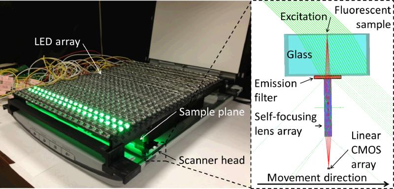
Along the same lines, here we demonstrate a cost effective platform (Fig. 1) for wide-field fluorescent imaging of micro-objects in scattering and absorbing medium. By creating a customized micro-fluidic channel, where the total volume is spread over a large area (e.g., 19 cm × 28 cm), and the height of the channel is only 60 μm, we can reduce the total optical path length in the sample, and thus avoid the excitation and emission losses due to dense scattering and absorbing properties of the medium. However, instead of scanning such a large area with a regular fluorescent microscope and digitally stitching thousands of microscopic images together, we modified the hardware and software of a conventional flatbed scanner and converted it into an ultra-wide field fluorescent imaging platform with a total FOV of ~532 cm2.
Fig. 1.
(Left) Experimental setup for the high-throughput fluorescent imaging platform combining a flatbed scanner, a custom-designed absorption filter, and a two-dimensional array of external light sources for computer-controlled and high-angle fluorescent excitation. The setup is capable of taking fluorescent measurements over a FOV of ~532 cm2 in less than 5 minutes. (Right) Schematic diagram of the light path inside the scanner head. The excitation light (green) arrives at a ~45° angle, and excites the fluorescent sample. The excitation does not reach the linear CMOS sensor of the scanner due to the low NA of the self-focusing lens array. The light scattered by the sample is attenuated by the emission filter, while the fluorescent emission passes through it. The gradient index lens array focuses the fluorescent light emitted by the sample onto the CMOS array.
To achieve this performance, we installed a two dimensional light-emitting-diode (LED) array (see Fig. 1) that is computer controlled for providing fluorescent excitation in the form of a “digitally” moving line that is matched to the speed of the scanner detector head. Each LED in this excitation array has a large illumination angle (~45°) with respect to the sample plane. Because of this large illumination angle of the LED array, most of the excitation photons are missed by the low numerical aperture (NA) collection optics that is located at the scanner detector head, creating a decent dark-field background that is required for fluorescent imaging. To further improve the rejection of the scattered excitation light and improve our SNR, we also installed a custom-designed absorbing filter right before the detector array and reprogrammed the driver of the scanner to achieve the highest possible exposure time, gain and sensitivity. We tested the performance of this ultra-wide field fluorescent imaging platform by detecting fluorescent micro-particles that are scattered within a large volume (~2.2 mL) of undiluted whole blood sample. Even though scanners have been used for bright-field biomedical imaging purposes earlier,18–23 our results constitute the first time that a flatbed scanner has been converted to a fluorescent imaging system, also achieving a record large FOV, i.e., 532 cm2.
Methods
In order to create a high-throughput fluorescent imaging platform, a large area microfluidic chip containing the sample is positioned onto the modified flatbed scanner (CanoScan LIDE 200F, ~65 USD) as illustrated in Fig. 1. The fluorescent excitation is provided by a computer controlled 2D array of LEDs, while the scanner's own internal light is turned off. Each LED of this illumination array is tilted by 45° which, in conjunction with the low numerical aperture of the gradient index self-focusing lens array inside the scanner head, ensures that the direct excitation does not reach the sensor array, unless there is a scattering event on the sample plane. To reject such scattered excitation photons, a custom-designed emission filter that is located right in front of the self-focusing lens array, significantly reduces the scattered light collection, while also letting the emitted fluorescent light pass through. This oblique illumination scheme, where the excitation light rays miss the image sensor (see Fig. 1), allows us to create a very strong dark-field background that is required for fluorescent imaging, without the need for sophisticated and costly fluorescent filters, such as thin-film interference filters. The software driver of the flatbed scanner was also modified to give us full control over the scanner features and obtain the highest sensitivity possible by the embedded opto-electronic detector array.
Oblique illumination set-up using a digitally controlled LED array
To create fluorescent excitation, we fabricated a 2D array of 30 × 20 green LEDs (HLMP-CM1A-450DD, ~0.5 USD/pcs) as shown in Fig. 1. These LEDs are placed 2 cm above the sample plane at an illumination angle of 45° (see Fig. 1) to create the required dark-field background for fluorescent imaging, and to provide uniform illumination over a large FOV, 19 cm× 28 cm. Two lines of LEDs (i.e., 20 × 2 LEDs) are independently controlled and digitally scanned during the forward motion of the scanner head. Therefore, according to the actual position of the scanner head during the image acquisition process, only two lines of LEDs are turned on at a given time to considerably reduce the power consumption of the system, and also to reduce the photo bleaching of the sample by only illuminating the immediate surroundings of the area seen by the moving scanner head.
Emission filter design
In order to create the absorptive material to be used as an emission filter, we dissolved 0.52 g red dye (Orasol Red BL, BASF) in 2 mL of cyclopentanone (≥99%, C112402, Sigma-Aldrich) and used rod coating (LAB3-5W, R.D. Specialties) to deposit a 11 μm layer to an optically clear ~100 μm thick transparent plastic (mylar) sheet (AZ42_9×11, Aztec), which was plasma treated before the coating process using a handheld high frequency generator (BD-10AS, Electro-Technic Products). We cut a strip from the coated mylar sheet and attached it to the scanner head right in front of the self-focusing lens array as illustrated in Fig. 1. The optical density of the filter at the excitation wavelength was measured as ~2.5, while at the emission region (i.e., above 600 nm) it was ~0.2.
Large-area microfluidic chip design
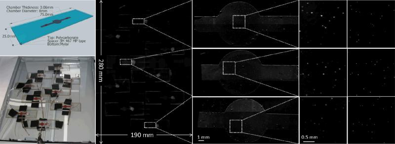
During our measurements we used two different types of microfluidic chambers. First, to validate the performance of the fluorescent scanner we created a sample holder which is compatible with a conventional fluorescent microscope (so that we can easily obtain comparison images). This chamber (see Fig. 2) was constructed by aligning and assembling a three layered sandwich structure. For the top layer we used a ~1 mm thick polycarbonate rectangle with the dimensions of 75 mm × 25 mm, which had two 1.7 mm holes for inlet/outlet. The middle layer, which serves as a spacer and creates the required height of the channel, is made of a 60 μm thick double-sided adhesive tape (3M 467 MP). The tape was patterned to create a disc-shaped chamber with 8 mm diameter, and a channel to connect the holes to this volume. The bottom layer, which faces the scanner, is made of a 100 μm thick transparent mylar sheet (AZ42_9×11, Aztec). After assembling with epoxy to be able to fill it with the liquid sample of interest.
Fig. 2.
(Left top) Schematic view of the microfluidic chips used in some of our experiments. An undiluted whole blood sample is spiked with 10μm fluorescent particles and filled into chamber volume. (Left bottom) Photograph of the experimental setup. The microfluidic chambers filled with the blood sample are positioned over the imaged area of scanner surface. (Middle left) The resulting image of the fluorescent scan over the full field-of-view (19 cm × 28 cm). (Middle right) Zoomed in regions of our results showing the scans of individual microfluidic chips. (Right) Further zoomed in regions of interests showing the signal obtained from individual 10μm fluorescent beads scattered within whole blood. (Far right) Comparison images taken with a conventional fluorescent microscope of the same regions of the microfluidic chips. Note that due to the liquid state of the sample, minor movement of some fluorescent beads occurred between the two imaging experiments (scanner vs. microscope). By comparing 9 different sample chambers, each of which contains on average ~190 particles, we achieved a 98.8% match in particle counting with approximately 1% standard deviation between our scanner based fluorescent imager and the microscope (4× objective lens, NA=0.13, with on average 12 overlapped microscope images per chamber to cover the sample FOV).
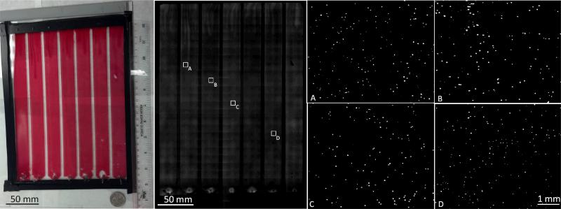
The second chamber (see Fig. 3) which utilizes the full field of view of the fluorescent scanner was created by using a similar technique. Here, the sample holder was constructed from a 3 mm thick 19 cm × 27 cm polycarbonate sheet as the top layer to increase the stiffness due to the larger chamber size. The spacer is the same 60μm thick double-sided adhesive tape. The pattern of the tape is such that total area is divided into 7 compartments each with an area of 22 mm × 244 mm corresponding to a total volume of 7 × 322 μL. We opted to use the scanner's own glass slide as the bottom of the chamber due to its high stiffness. Note that the slight variation of the position of the sample with respect to the focal point of the system is negligible due to the large depth of focus and the low NA of the detection optics. The total sample volume held by this chamber design is ~2.2 mL, which is imaged by the fluorescent scanner in <5 minutes.
Fig. 3.
Full field-of-view measurement results of whole blood spiked with 10 μm fluorescent particles. (Left) A photograph of the microfluidic chip. The chamber consists of 7 compartments each with a volume of 322 μl corresponding to a total volume of ~2.2ml per image. (Middle) Full field-of-view fluorescent scan of the same chamber. (Right) Zoomed in regions of interest showing the fluorescent particles inside thewhole blood sample.
Sample preparation
For spiking the fluorescent micro-particles (FluoSpheres 10 μm Red Fluorescent PS Microspheres PSFR010UM, MagSphere) into whole blood samples, we pipetted 2.5 μL of the particle solution into 3 mL of undiluted blood. After careful mixing, the sample is manually injected into the microfluidic chambers using a syringe.
Software control and modifications
In this work, unlike the previous approaches18–23 we took full control of the scanner to remove all of the image post processing steps used during conventional document scanning and to increase our fluorescent detection sensitivity. We used the open source application programming interface (API) package of the Linux operating system called Scanner Access Now Easy (SANE) as a starting point. The Canoscan LIDE 200F scanner applies an application specific integrated circuit (Genesys Logic GL847) as its central controller. The control of the scanner is realized by setting the appropriate registers of the controller to the desired values in the data stream sent to the scanner at the beginning of each scan. Since the SANE API has been developed for document scanning we had to add additional functionalities for fluorescent imaging. We turned off the built-in LED illumination, as we are using the external LED array as described earlier. We turned off the calibration step which sets the gain and the offset of each individual sensor pixel, prior to scanning, based on the scanned image of a white stripe glued to the scanner's document holding glass. In conventional document scanning, this step creates noise free uniform background, but in our case it would sacrifice sensitivity and reduce the dynamic range of our fluorescent imager platform. We set the pixel clock to the available minimum frequency to slow down the speed of the scanning and thus increase the exposure time to boost our digital SNR. We also increased the gain of the sensor to its maximum possible value. The resolution of the scan was set to 1200 dpi. The output of the device is 16-bit raw intensity information of the fluorescent emission from the sample plane. Note that, unlike 2D colour CMOS or CCD sensors, there are no embedded colour filters in our flatbed scanner, i.e., it uses a monochrome opto-electronic sensor chip.
Results and Discussion
We first evaluated the performance of our ultra large field of view (19 cm × 28 cm) fluorescence imaging system by screening spiked fluorescent particles (10 μm diameter) within undiluted whole blood samples injected into nine different microfluidic chips that are distributed across the field of view of our imaging system as illustrated in Fig. 2. In these initial experiments, we used smaller area micro-fluidic devices to be able to provide comparison images under a standard fluorescent microscope. Therefore, after our fluorescent scanning experiments, the same samples were also imaged with a regular fluorescent microscope (Olympus BX51) to provide gold standard comparison images. Evaluation of the results shown in Fig. 2 yields a very good match between our scanned fluorescent images and the microscope images in all of our samples, despite the highly scattering and absorbing nature of the blood sample within the micro-channel. At the edges of our micro-fluidic chambers the scattering from the sides of the channels partially overlap with the fluorescent signal of the beads, which can be further supressed with better fluorescent filters and/or different microfluidic chip designs.
Next, we performed imaging experiments using a large area microfluidic sample holder to demonstrate that a total volume of more than 2.2 mL of whole blood can be screened for fluorescent micro-particles in less than 5 minutes (see Fig. 3). These scanning results also provide a decent match to conventional fluorescent microscope images of the same samples, and further illustrate the rapid and accurate detection of fluorescent micro-objects within large volumes of optically dense and scattering media. These results, combined with the inexpensive materials and technologies used to create this fluorescent imaging platform, lead to a cost effective method for wide-field fluorescent imaging and cytometry. In addition to these, the presented ultra-wide field fluorescent imaging device still maintains the ease of use and portability of a regular flatbed scanner.
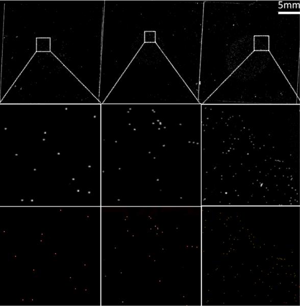
We next measured the sensitivity of the device by using fluorescent micro-beads of various sizes (5 μm, 7 μm, 10 μm) that were smeared on microscope coverslips, and compared the acquired scanning images of our platform to regular fluorescent microscope images (see Fig. 4), which also provided a decent agreement to our results even for 5 μm beads. Since the intensity of the scattered light from non-fluorescent objects within the sample (such as dust particles) is not completely blocked by our custom-designed cost effective absorption filter, such unwanted particles can also create a signal that is comparable to the intensity of fluorescent objects that are smaller than 5 μm. To image even smaller particles, this leakage can be avoided by using more advanced filters (e.g., thin film interference filters) to better reject the scattered excitation light before it is collected by the self-focusing lens-array of our platform.
Fig. 4.
Sensitivity of the fluorescent scanner (Top) Scanned fluorescent images of microscope coverslips containing monolayers of (from left to right) 10 μm, 7 μm and 5 μm fluorescent beads, respectively. (Middle) Zoomed in regions of interest, and (Bottom) their corresponding microscope comparisons. The contrast of the images was enhanced for better visibility. The original signal to noise ratio of the scanned images, before processing, was (from left to right) 17.6 dB, 14.7 dB, and 11.31 dB, respectively.
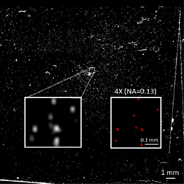
This imaging device is also sensitive enough to detect the emitted fluorescent light from labelled cells. To illustrate this, we labelled white blood cells with Ethidium Bromide (EtBr) and imaged a blood smear using our scanner based fluorescent imager; as shown in Fig. 5 individual white blood cells can be detected using our scanned fluorescent image. In this experiment, we lysed the red blood cells in 1 mL of whole blood sample using a red blood cell lysis buffer (Imgenex No. 10089) and added 0.5 μL of EtBr (Sigma, 10 mg/mL) to this solution and incubated it at room temperature for 45 minutes before we prepared the smear on a microscope coverslip. The imaging conditions and the settings of the scanner device were consistent with all the previous fluorescent experiments.
Fig. 5.
Scanned image of a microscope coverslip containing labelled white blood cells. Zoomed in region of the sample showing individual white blood cells and the corresponding fluorescent microscope comparison (4X objective lens with 0.13 NA) are also provided as insets. The contrast of the image was enhanced for better visibility.
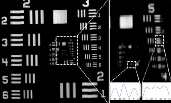
The resolution of flatbed scanners is typically reported in dots-per-inch by the manufacturer. This resolution, however, is the resolution of the interpolated final image, and should not be confused with the optical resolution. To quantify the optical resolving power of our flatbed scanner based fluorescent imaging platform, we imaged a resolution test target (i.e., a 1951 Air Force test target) as illustrated in Fig. 6. Through these resolution experiments, we determined that in our scanning geometry the half-pitch resolution of the grin lens array is ~3.9 μm, and therefore the relatively large pixel size of the CMOS sensor (i.e., ~5.3 μm × 20 μm) is the main limiting factor for our platform's resolution. Using the highest scan setting of the scanner (i.e., 4800 dpi), we measured the optical resolution of our system as 7.8 μm along the sensor direction and 12.4 μm along the scanning direction as illustrated in Fig. 6, where we define the spatial resolution in each direction as the line-width of the smallest period grating that can be resolved24. Over an imaging FOV of 19 cm × 28 cm, this corresponds to an effective pixel count of ~2.2 Giga-pixels, which is comparable to the space-bandwidth product of the state of the art micro-imaging systems that are based on e.g., lensfree on-chip holography14,24,25. Note that at a lower dpi selection (to speed up the image acquisition time), the resolution of our imaging platform will deteriorate.
Fig. 6.
The optical resolving power of the scanner based imager. (Left) 1951 Air Force test target scanned with 4800 dpi mode. (Top Right) Zoomed in region of the same image. The smallest resolved line-width is 7.8 μm along the sensor direction and 12.4 μm along the scanning direction. (Insets) The cross sections of the resolved grating lines are shown. 8× interpolation was used for better visualization of the resolution test.
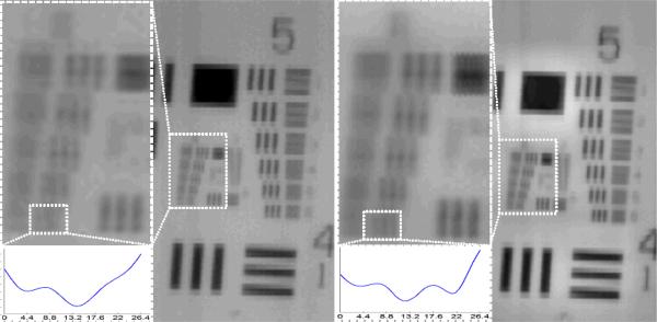
Since the resolution of our system is limited by the pixel size of the sensor, digital pixel super-resolution methods12–14,24–27 can be applied to increase the resolving power of our platform as also illustrated in Fig. 7, where a line-width of 4.4 μm can be resolved after pixel super-resolution is performed. We should emphasize that the regular scanning mechanism already generates shift-and-add like pixel super-resolution27 along the scanner head movement direction. As for the sensor direction, the required sub-pixel shifts to perform pixel super-resolution can be automatically generated in successive scans as the positioning error of the scanner device is larger than the pixel size of the sensor. Since this method requires several scans of the sample area, full field of view (e.g., 19 cm × 28 cm) implementation in a fluorescent setting might be challenging due to the speed of the scan and the photo-bleaching of the dyes. Nevertheless, as the scanning and data transfer speeds of future flatbed scanners increase, pixel super-resolution techniques can provide valuable methods to further increase the optical resolution and the space-bandwidth product of our scanning based fluorescent imaging system.
Fig. 7.
The effect of digital pixel super-resolution using 16 scanned images. The sample is a positive 1951 Air Force test target scanned with 4800 dpi mode. (Left) Scanned image with a zoomed in region into group 6 and an inset showing the non-resolved element 6. (Right) Super-resolved image with a zoomed in region into group 6 and an inset showing the spatial resolution improvement of element 6 corresponding to a line-width of 4.4 μm. 8× interpolation was used for better visualization of the resolution test.
Conclusions
We demonstrated a Giga-pixel fluorescent imaging modality that can screen for fluorescent micro-objects over a record-large FOV of ~532 cm2. This ultra-large FOV of our imaging platform allows us to screen > 2.2 mL of undiluted whole blood for detection of fluorescent micro-objects within < 5 minutes, making this high-throughput fluorescent imaging platform especially useful for rare cell research and cytometry applications. Our results constitute the first time that a flatbed scanner has been converted into a fluorescent imaging system.
Acknowledgements
Ozcan Research Group gratefully acknowledges the support of the Presidential Early Career Award for Scientists and Engineers (PECASE), Army Research Office (ARO) Life Sciences Division, ARO Young Investigator Award, National Science Foundation (NSF) CAREER Award, NSF CBET Biophotonics Program, NSF EFRI Award, Office of Naval Research (ONR) Young Investigator Award and National Institutes of Health (NIH) Director's New Innovator Award DP2OD006427 from the Office of the Director, National Institutes of Health.
Footnotes
Conflicts of Interest Statement
A.O. is the co-founder of a start-up company (Holomic LLC) which aims to commercialize computational imaging and sensing technologies licensed from UCLA.
References
- 1.Shaner NC, Steinbach PA, Tsien RY. Nat. Methods. 2005;2:905–909. doi: 10.1038/nmeth819. [DOI] [PubMed] [Google Scholar]
- 2.Zhang J, Campbell RE, Ting AY, Tsien RY. Nat. Rev. Mol. Cell Biol. 2002;3:906–918. doi: 10.1038/nrm976. [DOI] [PubMed] [Google Scholar]
- 3.Resch-Genger U, Grabolle M, Cavaliere-Jaricot S, Nitschke R, Nann T. Nat. Methods. 2008;5:763–775. doi: 10.1038/nmeth.1248. [DOI] [PubMed] [Google Scholar]
- 4.Arpali SA, Arpali C, Coskun AF, Chiang H-H, Ozcan A. Lab. Chip. 2012;12:4968–4971. doi: 10.1039/c2lc40894e. [DOI] [PMC free article] [PubMed] [Google Scholar]
- 5.Nagrath S, Sequist LV, Maheswaran S, Bell DW, Irimia D, Ulkus L, Smith MR, Kwak EL, Digumarthy S, Muzikansky A, Ryan P, Balis UJ, Tompkins RG, Haber DA, Toner M. Nature. 2007;450:1235–1239. doi: 10.1038/nature06385. [DOI] [PMC free article] [PubMed] [Google Scholar]
- 6.Stott SL, Hsu C-H, Tsukrov DI, Yu M, Miyamoto DT, Waltman BA, Rothenberg SM, Shah AM, Smas ME, Korir GK, Floyd FP, Gilman AJ, Lord JB, Winokur D, Springer S, Irimia D, Nagrath S, Sequist LV, Lee RJ, Isselbacher KJ, Maheswaran S, Haber DA, Toner M. Proc. Natl. Acad. Sci. 2010;107:18392–18397. doi: 10.1073/pnas.1012539107. [DOI] [PMC free article] [PubMed] [Google Scholar]
- 7.Sheng W, Chen T, Kamath R, Xiong X, Tan W, Fan ZH. Anal. Chem. 2012;84:4199–4206. doi: 10.1021/ac3005633. [DOI] [PMC free article] [PubMed] [Google Scholar]
- 8.Coumans FAW, van Dalum G, Beck M, Terstappen LWMM. Plos One. 2013;8:e61770. doi: 10.1371/journal.pone.0061770. [DOI] [PMC free article] [PubMed] [Google Scholar]
- 9.Park J-M, Lee J-Y, Lee J-G, Jeong H, Oh J-M, Kim YJ, Park D, Kim MS, Lee HJ, Oh JH, Lee SS, Lee W-Y, Huh N. Anal. Chem. 2012;84:7400–7407. doi: 10.1021/ac3011704. [DOI] [PubMed] [Google Scholar]
- 10.Sonnenberg A, Marciniak JY, Krishnan R, Heller MJ. ELECTROPHORESIS. 2012;33:2482–2490. doi: 10.1002/elps.201100700. [DOI] [PubMed] [Google Scholar]
- 11.Loutherback K, D'Silva J, Liu L, Wu A, Austin RH, Sturm JC. Aip Adv. 2012;2:042107–042107–7. doi: 10.1063/1.4758131. [DOI] [PMC free article] [PubMed] [Google Scholar]
- 12.McLeod E, Luo W, Mudanyali O, Greenbaum A, Ozcan A. Lab. Chip. 2013;13:2028–2035. doi: 10.1039/c3lc50222h. [DOI] [PMC free article] [PubMed] [Google Scholar]
- 13.Mudanyali O, McLeod E, Luo W, Greenbaum A, Coskun AF, Hennequin Y, Allier CP, Ozcan A. Nat. Photonics. 2013;7:247–254. doi: 10.1038/nphoton.2012.337. [DOI] [PMC free article] [PubMed] [Google Scholar]
- 14.Greenbaum A, Luo W, Su T-W, Göröcs Z, Xue L, Isikman SO, Coskun AF, Mudanyali O, Ozcan A. Nat. Methods. 2012;9:889–895. doi: 10.1038/nmeth.2114. [DOI] [PMC free article] [PubMed] [Google Scholar]
- 15.Zhu H, Sencan I, Wong J, Dimitrov S, Tseng D, Nagashima K, Ozcan A. Lab. Chip. 2013;13:1282–1288. doi: 10.1039/c3lc41408f. [DOI] [PMC free article] [PubMed] [Google Scholar]
- 16.Zhu H, Isikman SO, Mudanyali O, Greenbaum A, Ozcan A. Lab. Chip. 2012;13:51–67. doi: 10.1039/c2lc40864c. [DOI] [PMC free article] [PubMed] [Google Scholar]
- 17.Gorocs Z, Ozcan A. Biomed. Eng. Ieee Rev. 2013;6:29–46. doi: 10.1109/RBME.2012.2215847. [DOI] [PMC free article] [PubMed] [Google Scholar]
- 18.Levin-Reisman I, Gefen O, Fridman O, Ronin I, Shwa D, Sheftel H, Balaban NQ. Nat. Methods. 2010;7:737–739. doi: 10.1038/nmeth.1485. [DOI] [PubMed] [Google Scholar]
- 19.Taton TA, Mirkin CA, Letsinger RL. Science. 2000;289:1757–1760. doi: 10.1126/science.289.5485.1757. [DOI] [PubMed] [Google Scholar]
- 20.Yeh C-H, Hung C-Y, Chang TC, Lin H-P, Lin Y-C. Microfluid. Nanofluidics. 2009;6:85–91. [Google Scholar]
- 21.Sullivan K, Kloess J, Qian C, Bell D, Hay A, Lin YP, Gu Y. J. Virol. Methods. 2012;179:81–89. doi: 10.1016/j.jviromet.2011.10.003. [DOI] [PubMed] [Google Scholar]
- 22.Janzen MC, Ponder JB, Bailey DP, Ingison CK, Suslick KS. Anal. Chem. 2006;78:3591–3600. doi: 10.1021/ac052111s. [DOI] [PubMed] [Google Scholar]
- 23.Stroustrup N, Ulmschneider BE, Nash ZM, López-Moyado IF, Apfeld J, Fontana W. Nat. Methods. 2013 doi: 10.1038/nmeth.2475. advance online publication. [DOI] [PMC free article] [PubMed] [Google Scholar]
- 24.Greenbaum A, Luo W, Khademhosseinieh B, Su T-W, Coskun AF, Ozcan A. Sci. Reports. 2013;3 [Google Scholar]
- 25.Isikman SO, Greenbaum A, Luo W, Coskun AF, Ozcan A. Plos One. 2012;7:e45044. doi: 10.1371/journal.pone.0045044. [DOI] [PMC free article] [PubMed] [Google Scholar]
- 26.Bishara W, Su T-W, Coskun AF, Ozcan A. Opt. Express. 2010;18:11181–11191. doi: 10.1364/OE.18.011181. [DOI] [PMC free article] [PubMed] [Google Scholar]
- 27.Elad M, Hel-Or Y. Ieee Trans. Image Process. 2001;10:1187–1193. doi: 10.1109/83.935034. [DOI] [PubMed] [Google Scholar]


