Abstract
Lab-chip device analysis often requires high throughput quantification of fluorescent cell images, obtained under different conditions of fluorescent intensity, illumination, focal depth, and optical magnification. Many laboratories still use manual counting - a tedious, expensive process prone to inter-observer variability. The manual counting process can be automated for fast and precise data gathering and reduced manual bias. We present a method to segment and count cells in microfluidic chips that are labeled with a single stain, or multiple stains, using image analysis techniques in Matlab and discuss its advantages over manual counting. Microfluidic based cell capturing devices for HIV monitoring were used to validate our method. Captured CD4+ CD3+ T lymphocytes were stained with DAPI, AF488-anti CD4, and AF647-anti CD3 for cell identification. Altogether 4788 (76 × 3 × 21) gray color images were obtained from devices using discarded 10 HIV infected patient whole blood samples (21 devices). We observed that the automatic method performs similarly to manual counting for a small number of cells. However, automated counting is more accurate and more than 100 times faster than manual counting for multiple-color stained cells, especially when large numbers of cells need to be quantified (>500 cells). The algorithm is fully automatic for subsequent microscope images that cover the full device area. It accounts for problems that generally occur in fluorescent lab-chip cell images such as: uneven background, overlapping cell images and cell detection with multiple stains. This method can be used in laboratories to save time and effort, and to increase cell counting accuracy of lab-chip devices for various applications, such as circulating tumor cell detection, cell detection in biosensors, and HIV monitoring devices, i.e. CD4 counts.
Introduction
Biomedical research often requires enumerating cells, labeled with multiple fluorescent markers, which are captured on labchip devices. Examples are: circulating tumor cell detection,1 cell detection in biosensors2 and CD4 counting devices.3–5,20,21 Flow cytometry techniques offer reliable cell quantification. However, this is an expensive process that requires cells to be suspended in solution.6 Other cell quantification methods include cell counting chambers, microFACS7 and capturing of fluorescently stained cells in microfluidic devices. In the latter method, cells are imaged using a camera attached to a fluorescent microscope, followed by manual counting of the various resultant fluorescent images. Although this method is effective, manual counting is a slow process that lacks standardized accuracy, as it is subject to inter-operator variance.8
Image processing techniques allow segmenting and counting stained cell images on lab-chip devices. However, due to differences in microfluidic devices, cell morphology, staining techniques, and imaging conditions, there is no standard method to segment all cell images. Most current image segmentation methods are task specific; for instance, they count cell nuclei,9 determine cell morphology,10 or quantify features of specific cell types.11,12 Methods are needed to count cells on microfluidic chips that simultaneously express two or more fluorescent stains.1,4
Conventional image segmentation techniques include thresholding selection, edge detection, and active contour. The thresholding method does not retain spatial information that is used during image segmentation.13 Thresholding also cannot always be applied to counting imaged cells in microfluidic devices, since some images contain unevenly distributed background noise with higher intensity than that of the cells of interest. Thresholding methods often work with morphological operators to improve the segmentation accuracy.14,15 Edge detection is inadequate for cell segmentation because not all cell boundaries are sharp, making it challenging to accurately detect all cells.16 Active contour models use the gradient flow vector applied to initial circular shapes placed inside the cells. These models are usually preceded by image conversion into binary format using double thresholding, and a subsequent search for cells whose intensity exceeds the threshold value. This approach, however, suffers from false maxima and false edge points due to the uneven background intensity.13,17
To alleviate the aforementioned shortcomings, we introduce a simple, yet accurate method to segment and count cells on microfluidic devices. The method takes into consideration the challenges related to cell imaging on a microfluidic chip. Our algorithm consists of a pre-processing step for automatic background elimination through morphological operators, a cell detection step that detects local maxima and performs local thresholding, and a stain comparison step that compares cell positions in images taken under various fluorescent filters at the same location on the microfluidic device to determine if each cell expresses one or more fluorescent markers. This software is tested on DAPI, AF488-anti CD3, and AF647-anti CD4 stained white blood cells captured on two types of microfluidic chips. Our algorithm recognizes each DAPI stained cell and verifies whether that cell was CD3+ and CD4+. It outputs the number of CD3+ CD4+ T-lymphocytes, which is of crucial interest for HIV monitoring.4 This method is more accurate and more than 100 times faster than manual counting.
Summary of the algorithm
First, the background was subtracted and the image was amplified. Then, the image was dilated using a disk-shaped structuring element.18 Next, the local maximum was determined using morphological operators and a local thresholding technique was applied to each local maximum in the image. The same step was applied to all three images for the distinct stains; then each of the CD3+ cells was checked for expression of other stains (i.e. DAPI and CD4+), and the number of cells that expressed all three stains was determined (Figure S1, ESI).†
Image acquisition
We used 21 microfluidic chips that captured CD4+ T lymphocytes from 10 discarded HIV infected patient whole blood samples. We tested our algorithm on two sets of images obtained from two different kinds of microfluidic devices. The first set represents images of white blood cells stained with DAPI, AF488-anti CD3, and AF647-anti CD4 which were captured in a microfluidic channel using surface chemistry.4 The images of the full device were taken sequentially using the microscope and a movable stage. The stage was moved systematically to ensure that the same area was not imaged twice. The image program (Spot Advanced software) saved the images with auto-increment numbers in their file names. Based on these numbers, the program first read all the images in a folder then opened each image sequentially, analyzing three images (1 “blue”, 1 “green”, and 1 “red”) at a time.
The second set represents images of white blood cells stained for CD3, and CD4 which were captured using porous nano-filters.19,20 The stained cells were detected through a fluorescence microscope (Nikon Eclipse, TE2000-U, Japan) with a CCD camera (Spot RTKe Diagnostic Instruments Inc., MI). For the first set, “UV”, “blue”, and “green” filters were used for the three stain types (DAPI, AF488-anti CD3 antibody, and AF647-anti CD4 antibody), respectively. Images were taken with a 10× Epi objective lens through each of the three filter cubes (UV-2E/C DAPI, FITC HYQ, Cy5 HYQ, Nikon, Japan). To use these filter cubes, three fluorescent probes were utilized adopting the excitation and emission wavelengths, 356/458 nm for DAPI, 499/520 nm for AF488, and 652/667 nm for AF647. All cells were imaged using the same method and parameters, i.e. exposure time, focus, and gain. For the second set, the stained cells were detected by a fluorescence microscope featuring “blue” and “green” filters for CD3, and CD4 stains, respectively. Images for this set were taken at 4× magnification. Consequently, a single image detailed the entire device (4 mm long × 4 mm wide).
Image pre-processing
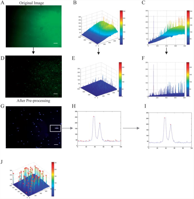
Undesired shading effects and intensity variations in the image can hamper cell detection. Such effects were therefore minimized and eliminated by evening out the background using Matlab's background subtraction method, as described in the manual.18 First, the pixel value of the background was estimated using a morphological opening operation in Matlab's Image Processing Toolbox (Version 2.2.2 R12). This operation is composed of erosion22 followed by dilation,23 using a structuring element that was larger than the pixel-size of the cells. The obtained background value was then subtracted from the original image. Finally, the image contrast in the background-corrected image was adjusted by linearly mapping the pixel values onto a larger scale to increase the overall image contrast (Fig. 1 A–F). Combining background subtraction with the amplification method allowed us to eliminate the background without losing the pixel values of the cells.
Fig. 1.

Background subtraction and cell detection. The original image (A) is plotted in three dimensions (B). The image was viewed along the x-z axis (C), the background increases from <25 to >150 from left to right. The image was then processed (D) and plotted in three dimensions after background subtraction (E). It was also viewed along the x-z axis (F), the background was always <50 without losing signal intensity for the objects of interest (cells). Detecting a local maximum in the intensity profile across a portion of one image (G), all the local maxima were determined (H), a local thresholding method was then applied to the image to separate cells from background (I). Local maxima followed by local thresholding was applied to the image, shown in 3-D (J). In (B,E) the x-y axis labeling corresponds to pixels whereas the z axis labeling corresponds to intensity. In (C,F,H,I) the x axis labeling corresponds to pixels whereas the y axis labeling corresponds to intensity (8bit, 0∼255). The scale bar is 100 μm.
Cell recognition
To detect cells, all local maxima within the image were first detected. A morphological dilation function23 that uses a disk with a diameter that matches the cell diameter (5 pixels for a 4× image and 12 pixels for a 10× image) was applied to each image (following CCD specification, controllable cell diameter adjustment to match different magnifications and cell types); the original image was compared to the dilated one and the maxima were identified (Fig. 1 G,H). An exclusion method was applied to exclude points with identical intensity. This is done by adding noise to the image without affecting the peaks.
Next, a local thresholding method was applied to each local maximum in the image to distinguish maxima that represented cells from background noise peaks (Fig. 1 I). Local thresholding was done by comparing the cell to four points residing around each maximum (Fig. 1 J). If any of the four differences exceeded the threshold, the maximum was identified as a cell.
Multiple stain comparison
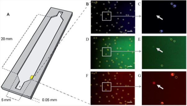
The software can quantify the number of cells that are labeled with more than one stain. In HIV testing devices, for example, a certain type of white blood cells (T-lymphocytes), which have CD3 and CD4 receptors on their membrane, need to be counted.4 After each sample was labeled with all three stains, and flowed into a microfluidic device, images were taken under three fluorescent filters. Object locations were recognized under “green” fluorescence (CD4+ cells), and then compared to pixels in the same location on the “blue” image (DAPI stained image). Only if a cell candidate was found in that specific location was the object counted as a cell. Those cells were then compared to the CD3+ cells (“red images”), and the number of cells that were fluorescent for DAPI, CD4, and CD3 was obtained. The cells were marked by the program with circles (Fig. 2 A–G). Arrows in the figure were added to show an object that was present in the “red image” but absent in the “blue image”. Such an object was not counted as a cell by the algorithm, and was hence not marked with a circle by the software.
Fig. 2.

Drawing of the microfluidic device used to capture T lymphocytes using surface chemistry (A). Fluorescent images of cells stained with DAPI (B), CD4 (C), and CD3 (D). All cells in the DAPI image are marked. The DAPI image is used as a base for CD4 and CD3. The location of each cell in the DAPI image is compared to that in the processed CD4 and CD3 images. If a cell candidate in those images exceeds a certain threshold, the program marks it as a cell. The circle indicates what the program considers “a cell”; the arrows show objects that are not considered cells since they were not found in all three stains. Scale bar corresponds to 100 μm.
It took 5–9 hours to manually count one device of this type (228 of these 10× images). The manual counting was done by trained lab technicians who manually counted each DAPI image and performed a cell by cell comparison to CD3+ and CD4+ cells and reported the number. The software automatically counted all the images of this device in 3–6 minutes on a laptop computer (Intel Centrino Duo CPU T2050 @ 1.6GHz), and analyzed multiple images of different stains. Here, the automated counting was about 100 times faster than manual counting.
Parameters
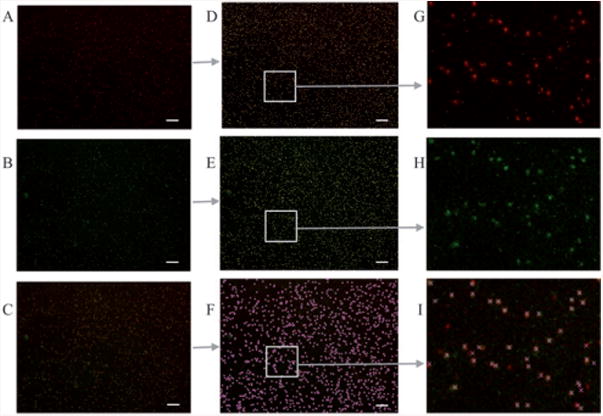
Two parameters were adjustable in our code: cell size and threshold. ‘Cell size’ determined the disk size used in the morphological operator. This allowed separating adjacent cells; our method overcomes the issue of adjacent cell separation (Figure S2, ESI)† which is generally a problem for automated cell counting programs that are based on edge detection. Having the cell size as a free parameter makes this program useful for counting images at different magnifications as well as images with different cell types. For example, the ‘cell size’ is around 5 pixels in a 4× image, and around 12 pixels in a 10× image. The program was used to count 4× images of T lymphocytes captured on a microfluidic filter (Fig. 3 A–I). Imaging under low magnification (4×) allowed capturing the full device in one single image for each fluorescent stain. Counting this device (represented by 1 “red”, and 1 “green” image only) automatically took 3 to 5 seconds. Manual counting of these three highly populated images took 5 hours. Hence, in this case the automated method provided over 3000 times faster counting. The threshold parameter determines the difference between the pixel intensity of the cells and that of the adjacent surrounding background. It is important to control this parameter since the relative intensity of the stains varies based on microfluidic device type, staining and imaging conditions.
Fig. 3.

Cells in 4× images on microfluidic filters. Enumeration is often required for 4× images, more than 3000 cells per image, with over 1000 cells that fluoresce for both CD3 and CD4. (A,B) correspond to CD3+ and CD4+ stained cells, respectively. (C) is a merged image of A and B. (D,E,F) are counted versions of A, B, and C. (G,H,I) are the magnified portions of D, E, and F. Counting these images automatically takes 3–5 seconds. Manual counting of these highly populated images take 5 hours. Hence, in this case the automated method provides over 3000 times faster counting. Scale bar corresponds to 200 microns.
Statistical analysis
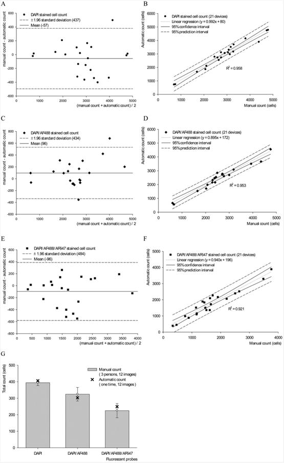
Results from the software-based automated counting of fluorescently stained cells for the first set (the surface chemistry treated microfluidic device) were compared to manual counting of those images using a paired t-test, with 95% confidence level. The correlation between the two methods was also determined using the Pearson correlation test. Moreover, the Passing & Bablok regression24 correlation test was used to determine the linear regression between counting results based on the two methods, i.e. manual and automated. The degree of concordance between the two methods was established using Bland Altman statistical analysis.25,26
Both the Pearson's correlation test, and the paired Student's t-test indicates a strong correlation (Table 1). The Bland and Altman plot indicated that there was no significant difference between automated and manual quantification methods. Results of comparing the two methods versus the average of the two methods, for DAPI, DAPI/CD4+, and DAPI/CD4+/CD3+ sample, are shown (Fig. 4 A–C). The Passing and Bablok regression also showed the difference between the two methods, and the limits of concordance for the 95% confidence interval (Fig. 4 E–G) along with the equations and the coefficient of determination (R2). Each device of this type required 5–9 hours of manual counting, versus 3–6 min when counted using our software.
Table 1. Correlation tests from manual vs. automated counting.
| DAPI | DAPI/CD3+ | DAPI/CD3+/CD4+ | |
|---|---|---|---|
| Pearson Correlation | 0.979 | 0.977 | 0.960 |
| Paired T-test (P value) | 0.249 | 0.059 | 0.089 |
| R2 | 0.958 | 0.954 | 0.921 |
Fig. 4.

Statistical analysis of the automated and manual counts of DAPI, CD4+, and CD3+ stained images. Bland-Altman plot of the automated versus the manual count of DAPI+, DAPI+/CD4+ and DAPI+/CD4+/CD3+ cells, (A–C) showing the error and limit of agreement. Comparison using Passing and Bablok Regression is shown (E–G), with the 95% confidence interval and the regression equation. The variability of manual counting was obtained by having 3 counters counting the same 12 sets of images (D). We notice that the variability (error bars) increased when the task was to identify multiple stains; the automated count was within the standard deviation for all three cases. R2 values were 0.958, 0.954, and 0.921 for E, F, and G, respectively.
For each device, the ‘average cell size’ and the ‘threshold’, which vary based on the magnification and the fluorescence intensity, were selected using a test set of images. The free parameters were locked and used to perform automatic counting of the rest of the device (on average ∼228 images per device).
All devices were counted automatically, and the results were evaluated by comparing them with manual counting results of the same images.
The variability among human counters was accounted for by having 3 different counters reporting the number of cells for the same 12 sets of images. Results were also compared to those generated by the software. The manual counting results varied considerably among counters, and the variability increased significantly when the task was to count cells that were positively stained for all the three stains (Fig. 4 D).
Conclusion
Lab-on-chip devices require high throughput quantification of fluorescently stained cell images that are taken under different fluorescent intensity, illumination, focal depth, and optical magnification. Manual counting is tedious, expensive and varies from observer to observer. This process can be automated for fast and standardized data gathering regardless of manual bias. We presented a method to quantify fluorescently-stained cells captured on a microfluidic chip using image analysis techniques. We verified our system using microfluidic chips that captured CD4+ T lymphocytes using 10 discarded HIV-infected patient whole blood samples. White blood cells captured in 21 devices stained with DAPI, CD4 and CD3 fluorescent antibodies were counted using this algorithm. In addition to the accuracy and the time savings (100×), the software can also be used to obtain cell location and cell distribution on a microfluidic device. This approach may prove beneficial to other cell capture based lab-chip devices and further studies on cell locomotion or cell capture mechanisms.
Supplementary Material
Acknowledgments
We would like to acknowledge the Center for Integration of Medicine and Innovative Technology (CIMIT) Award and the W. H. Coulter Foundation Young Investigator Award in Bioengineering, and NIH R01-AI081534. We would like to thank Syed Hasan for reviewing the paper, and Emine S. Turali, and Ahmet E. Emre for providing help with counting.
Footnotes
Electronic supplementary information (ESI) available: Fig. S1 and S2 and Legends for the Code and test images. See DOI: 10.1039/b911882a
Author contributions: MA developed the algorithm, analyzed the data, and wrote the paper. SJM fabricated devices, designed experiments, analyzed images, and wrote the paper. HOK, FM and RL contributed to the imaging and analysis of devices and images. EH contributed to the analysis and writing of the paper. DK supervised the clinical aspects of the HIV experiments. UD supervised the project and experiments, analyzed the results, and wrote the paper.
References
- 1.Nagrath S, et al. Isolation of rare circulating tumour cells in cancer patients by microchip technology. Nature. 2007;450:1235–1239. doi: 10.1038/nature06385. [DOI] [PMC free article] [PubMed] [Google Scholar]
- 2.Oh TI, Sung JH, Tatosian DA, Shuler ML, Kim D. Realtime fluorescence detection of multiple microscale cell culture analog devices in situ. Cytometry A. 2007;71:857–865. doi: 10.1002/cyto.a.20427. [DOI] [PubMed] [Google Scholar]
- 3.Moon SJ, Lin R, Demirci U. CD4 + T-lymphocyte capture using a disposable microfluidic chip for HIV. J Vis Exp. 2007;315 doi: 10.3791/315. [DOI] [PMC free article] [PubMed] [Google Scholar]
- 4.Moon SJ, Keles HO, Ozcan A, Khademhosseini A, Haeggstrom E, Kuritzkes DR, Demirci U. Integrating microfluidics and lensless imaging for point-of-care testing. Biosens Bioelectron. 2009 doi: 10.1016/j.bios.2009.03.037. [DOI] [PMC free article] [PubMed] [Google Scholar]
- 5.Ozcan A, Demirci U. Ultra wide-field lens-free monitoring of cells on-chip. Lab Chip. 2008;8:98–106. doi: 10.1039/b713695a. [DOI] [PubMed] [Google Scholar]
- 6.Sakamoto C, Yamaguchi N, Nasu M. Rapid and simple quantification of bacterial cells by using a microfluidic device. Appl Environ Microbiol. 2005;71:1117–1121. doi: 10.1128/AEM.71.2.1117-1121.2005. [DOI] [PMC free article] [PubMed] [Google Scholar]
- 7.Fu AY, Spence C, Scherer A, Arnold FH, Quake SR. A microfabricated fluorescence-activated cell sorter. Nat Biotechnol. 1999;17:1109–1111. doi: 10.1038/15095. [DOI] [PubMed] [Google Scholar]
- 8.Piuri V, S F, editors. CIMSA. Computational Intelligence for Measurement Systems and Applications; 2004 IEEE International Conference on, Dept. of Inf. Technol., Milan Univ.; Crema, Italy. 2004.2004. pp. 103–108. [Google Scholar]
- 9.Netten H, et al. FISH and chips: automation of fluorescent dot counting in interphase cell nuclei. Cytometry. 1997;28:1–10. [PubMed] [Google Scholar]
- 10.Mao-jun Su, Zhao-bin Wang, Hong-juan Zhang, Yi-de M., editors. ISCCSP 12–14. Malta: 2008. [Google Scholar]
- 11.Glory E, et al., editors. Image Analysis and Recognition. 2004. pp. 84–91. [Google Scholar]
- 12.Wahlby C, Lindblad J, Vondrus M, Bengtsson E, Bjorkesten L. Algorithms for cytoplasm segmentation of fluorescence labelled cells. Anal Cell Pathol. 2002;24:101–111. doi: 10.1155/2002/821782. [DOI] [PMC free article] [PubMed] [Google Scholar]
- 13.Theerapattanakul J, Plodpai J, Pintavirooj C, editors. Proceeding of the 2004 IEEE Region 10 Conference (TENCON 2004) Thailand: 2004. pp. 191–194. [Google Scholar]
- 14.Di Rubeto C, Dempster A, Khan S, Jarra B, editors. Proceedings of the International Conference on Pattern Recognition - Volume 3. IEEE Computer Society; 2000. [Google Scholar]
- 15.Anoraganingrum D, editor. ICIAP ′99: Proceedings of the 10th International Conference on Image Analysis and Processing. IEEE Computer Society; 1999. [Google Scholar]
- 16.Jeacocke MB, Lovell BC, editors. Intelligent Information Systems 1994. Proceedings of the 1994 Second Australian and New Zealand Conference on 322–326; 1994. [Google Scholar]
- 17.Katz SW, Brink AD, editors. Communications and Signal Processing 1993. Proceedings of the 1993 IEEE South African Symposium on 85–90; 1993. [Google Scholar]
- 18.Matlab 7.5. The MathWorks, Inc; 2007. [Google Scholar]
- 19.Rodriguez WR, et al. A microchip CD4 counting method for HIV monitoring in resource-poor settings. PLoS Med. 2005;2:e182. doi: 10.1371/journal.pmed.0020182. [DOI] [PMC free article] [PubMed] [Google Scholar]
- 20.Jokerst JV, Floriano PN, Christodoulides N, Simmons GW, McDevitt JT. Integration of semiconductor quantum dots into nano-bio-chip systems for enumeration of CD4 + T cell counts at the point-of-need. Lab Chip. 2008;8:2079–2090. doi: 10.1039/b817116e. [DOI] [PMC free article] [PubMed] [Google Scholar]
- 21.Cheng X, Irimia D, Dixon M, Ziperstein JC, Demirci U, Zamir L, Tompkins RG, Toner M, Rodriguez WR. A Microchip Approach for Practical Label-Free CD4+ T-Cell Counting of HIV-Infected Subjects in Resource-Poor Settings. JAIDS Journal of Acquired Immune Deficiency Syndromes. 2007;45:257–261. doi: 10.1097/QAI.0b013e3180500303. [DOI] [PubMed] [Google Scholar]
- 22.Gonzalez R, Woods R. Digital Image Processing. 2nd. Prentice Hall; 2002. [Google Scholar]
- 23.Dougherty ER S. o. P.-o. I. Engineers. An introduction to morphological image processing. Edward R Dougherty; Bellingham, Wash, USA: 1992. [Google Scholar]
- 24.Passing H, Bablok A new biometrical procedure for testing the equality of measurements from two different analytical methods. Application of linear regression procedures for method comparison studies in clinical chemistry, Part I. J Clin Chem Clin Biochem. 1983;21:709–720. doi: 10.1515/cclm.1983.21.11.709. [DOI] [PubMed] [Google Scholar]
- 25.Altman DG, Bland JM. Measurement in medicine: the analysis of method comparison studies. Statistician. 1983;32:307–317. [Google Scholar]
- 26.Bland JM, Altman DG. Statistical methods for assessing agreement between two methods of clinical measurement. Lancet. 1986;1:307–310. [PubMed] [Google Scholar]
Associated Data
This section collects any data citations, data availability statements, or supplementary materials included in this article.


