

Significance
Animals often produce substantial forces in directions that do not directly contribute to movement. For example, running and flying insects produce side-to-side forces as they travel forward. These forces generally “cancel out,” and so their role remains a mystery. Using a multidisciplinary approach, we show that mutually opposing forces can enhance both maneuverability and stability at the same time, although at some energetic cost. In addition to challenging the maneuverability–stability dichotomy within locomotion, our results challenge the same tradeoff within the engineering of mobile robots. This may inspire the exploration of a new set of strategies for the design and control of mobile systems.
Keywords: bioinspired robotics, biomechanics
Abstract
A surprising feature of animal locomotion is that organisms typically produce substantial forces in directions other than what is necessary to move the animal through its environment, such as perpendicular to, or counter to, the direction of travel. The effect of these forces has been difficult to observe because they are often mutually opposing and therefore cancel out. Indeed, it is likely that these forces do not contribute directly to movement but may serve an equally important role: to simplify and enhance the control of locomotion. To test this hypothesis, we examined a well-suited model system, the glass knifefish Eigenmannia virescens, which produces mutually opposing forces during a hovering behavior that is analogous to a hummingbird feeding from a moving flower. Our results and analyses, which include kinematic data from the fish, a mathematical model of its swimming dynamics, and experiments with a biomimetic robot, demonstrate that the production and differential control of mutually opposing forces is a strategy that generates passive stabilization while simultaneously enhancing maneuverability. Mutually opposing forces during locomotion are widespread across animal taxa, and these results indicate that such forces can eliminate the tradeoff between stability and maneuverability, thereby simplifying neural control.
Animals routinely produce muscle commands that result in “antagonistic” (mutually opposing) forces during locomotion that either cancel out at each instant of time or average to zero over each gait cycle (1–5). This may seem surprising because these antagonistic forces do not contribute to the cycle-averaged movement of the center of mass of the animal. Such antagonistic forces are not only present during forward locomotion but in hovering for animals such as hummingbirds, hawkmoths, and electric fish; these animals produce large antagonistic forces and exhibit extraordinary maneuverability during station keeping (6–9). In this study, we demonstrate that active generation and differential control of such antagonistic forces can eliminate the tradeoff between stability and maneuverability during locomotion.
Stability is generally defined as the resistance to, and recovery from, disturbances to an intended trajectory (10). Although maneuverability can be defined in several ways (11, 12), it is perhaps most generally recognized as the relative amplitude of the control signal required to change movement direction (13). That is, if a small change in the control amplitude effects a rapid change in direction, the system would be considered highly maneuverable. The potential for a tradeoff between the resistance to changes in direction and the ability to change direction appears self-evident (5, 10, 13, 14), and this tradeoff is indeed considered a fundamental challenge for the engineering design of airborne, submarine, and terrestrial vehicles (14–17). Many swimming, flying, and running animals, however, appear to use locomotor strategies that are extremely stable and yet facilitate the control of extraordinary maneuvers (4, 10, 18, 19).
To investigate the relationship between antagonistic forces and locomotor control, we studied the glass knifefish, Eigenmannia virescens, that hovers and rapidly changes direction while producing opposing forces using a single elongated fin (Fig. 1A). Glass knifefish, like other knifefish, generate thrust force primarily through undulatory motions of an elongated anal fin (20–22). The ribbon fin consists of 217 ± 27 downward-pointing rays (table 4 in ref. 23; all statistics are quoted as mean ± SD unless otherwise noted), with each ray independently controlled by a set of muscles. These rays are oscillated in a plane transverse to the body axis and can be coordinated to produce a wave that travels longitudinally along the fin. In this study, we integrate biological experiments (Fig. 2), computational modeling, and experiments with a biomimetic robot (Fig. 1B and Fig. S1) to understand how the fish achieves both stability and maneuverability during rapid adjustments of its fore–aft position. Eigenmannia and other similar species of knifefish often partition their ribbon fin into two inward-counterpropagating waves (22) (Movie S1). The fin kinematics can be idealized as a pair of inward-traveling waves with parameters including oscillation frequency (f), wavelength (λ), and angular amplitude (θ) (Fig. 1C). We term the point where these two waves meet the “nodal point.” Although much is understood about the kinematics and mechanics of unidirectional traveling waves in a fluid (20, 24–28), far less is known (22, 29) about counterpropagating waves, particularly in relation to control.
Fig. 1.

Three testbeds considered in this paper include the glass knifefish, a biomimetic robot, and a model of the swimming dynamics. (A) The glass knifefish E. virescens. Experiments with a biomimetic robot match force measurements predicted by a computational model of ribbon fin propulsion. (B) A biomimetic robot that has a ventral ribbon fin to emulate the fin of knifefish. The biomimetic robotic fin consists of 32 independently controlled rays, allowing for a wide range of fin kinematics, such as counterpropagating waves. (C) Fin is modeled as a pair of inward-traveling waves. Directions of head and tail waves and kinematics of the ribbon fin are shown in this schematic: angular deflection (θ), wavelength (λ), lengths of the two waves (Lhead and Ltail), length of whole fin (Lfin), temporal frequency (f), and nodal point (red circle).
Fig. 2.
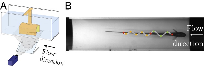
Experimental apparatus. (A) The steady-state flow (0–12 cm/s) direction is shown. The fish keeps itself stationary relative to the PVC tube, and the kinematics of the ribbon fin are recorded from below through an angled mirror. (B) One annotated frame recorded from the experiment is shown. Both ends of the fin and nodal point are shown in red. All peaks and troughs of head and tail waves are shown with green and orange dots, respectively.
Results
Using high-speed videography at 100 frames per second, the kinematics of the ribbon fin of five fish were digitized during station keeping (Fig. 2 and Fig. S2). Individual fish were placed in the test section of the flow tunnel. When we varied the steady-state flow speed, the fish typically remained stationary relative to a refuge mounted in the flow tunnel. A single trial consisted of a fish remaining stationary in the refuge by swimming forward (into the flow) at the flow speed. For each trial and flow speed, we analyzed 1-s intervals (100 video frames) while the fish maintained position. Trials were conducted at nine flow speeds (flow moving from head to tail in all cases) between 0 and 12 cm/s in increments of 1.5 cm/s. The order of these nine trials was pseudorandomized, and three sets (replicates) of trials were collected for each individual, totaling 27 experiments per fish. The masses of the individuals averaged 2.80 ± 0.72 g. The fin and body lengths were 7.36 ± 0.57 cm and 11.59 ± 0.71 cm, respectively. As shown in Fig. 3A, the ribbon fin typically organized itself into two inward-counterpropagating waves. In four trials at the highest speed tested (12 cm/s), the ribbon fin had transitioned into a single wave traveling from head to tail.
Fig. 3.

E. virescens partitions its fin into two inward-counterpropagating waves that produce antagonistic thrust forces. (A) Both ends of the fin and the nodal point (red cross), all peaks and troughs of the head wave (green circles), and all peaks and troughs of the tail wave (orange circles) were tracked during station keeping at different swimming speeds. The nodal position at t = 0 was taken as the reference for rostrocaudal position. Nodal point shift,  , from 0 cm/s flow speed (no ambient flow) to 4.5 cm/s flow speed of a representative dataset is shown in A. (B) Nodal point shifts caudally as a function of flow speed approximately linearly. At each tested flow speed, the average over all replicates of data is shown with a filled circle. Shaded regions indicate the full range of nodal point shifts for all trials and all fish.
We found that the nodal point moved toward the tail as a function of increased head-on flow speed (Fig. 3B). The nodal point shift,  , was measured for each trial; here, Lhov corresponds to the nodal point position during hovering (U = 0) and Lflow corresponds to the test condition (U > 0). Other kinematic parameters varied less substantially with flow speed (Fig. S3). The nodal point shift of one replicate from one fish was an outlier quantitatively, and therefore was removed from statistical analyses (SI Data and Discussion and Fig. S4). All other replicates from all fish were quantitatively similar within and across individuals.
The effect of nodal point position on the net thrust force generated by two inward-counterpropagating waves was investigated using a biomimetic robot (Fig. 1B and Fig. S1) and a computational model (Materials and Methods). In the first set of experiments with the biomimetic robot, the nodal point position was varied while other properties of the traveling waves were held constant. Thrust forces generated by the two traveling waves were also predicted numerically. The measured forces as a function of nodal point shift closely match simulated forces from our model (Fig. 4A). The thrust force varied linearly as a function of nodal point shift. We define the nodal point shift gain, κ, as the ratio of the measured net force to the nodal point shift:
 |
This parameter indicates the change in force given a unit change in nodal point position, and it is used as a metric for fore–aft maneuverability of counterpropagating waves. Note that the nodal shift gain, κ, increases as a function of frequency (f) and angular amplitude of counterpropagating waves (θ) (Fig. S5). κ increases approximately quadratically with the frequency (Fig. 4B).
Fig. 4.
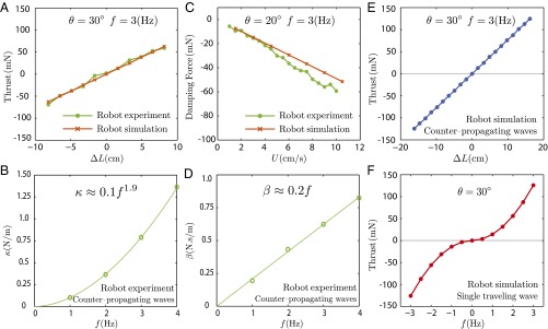
Biomimetic robot experiments and simulations. (A) Measured forces varied linearly as a function of nodal shift  . The slope is termed the nodal shift gain. (B) Counterpropagating waves were driven at four frequencies [parameters are shown in Table S1 (set 1)]). The nodal shift gain varied nonlinearly as a function of frequency. (C) Forces acting on the robotic fin varied approximately linearly as a function of steady-state flow speed when the nodal point was held in the middle of the fin
  ; the negative of the slope was termed the damping constant. (D) Damping constant varied linearly as a function of frequency [parameters are shown in Table S2 (set 1)]. (E and F) Comparison of thrust generation by varying only one kinematic parameter predicted by the computational model. (E) Net thrust force is a linear function of nodal position. The nodal point is in the middle of the fin when
  . (F) Net thrust force by a single traveling wave along the fin is nonlinear with zero slope at f = 0, namely, Force
  . Negative frequency means the wave direction is reversed. Note that near zero net thrust, large changes in frequency are required to generate small changes in force because the graph has a slope of 0 at f = 0. The fin does not move when f = 0.
We also discovered that passive damping emerges with counterpropagating waves. Specifically, a damping force opposing the direction of velocity perturbations increases linearly as a function of the speed of the animal relative to the flow. To measure this drag-like term in the robotic setup, the nodal point was held at the center of the robotic fin  , making the length of the fin dedicated to the tail wave (Ltail) identical to the length of fin dedicated to the head wave (Lhead). The measured forces produced by the biomimetic robot vary linearly as a function of steady-state ambient flow and closely match simulated forces from our model (Fig. 4C). Here, we define the damping constant, β, as the ratio of the measured damping force, F, to the flow speed, U:
 |
Larger values of the damping constant correspond to greater stability, in the sense that the time constant associated with recovery from perturbations is the ratio of inertia to damping (4, 18, 30). Note that the damping constant increases with frequency (f) and angular amplitude (θ) of counterpropagating waves (Fig. S6). In particular, the damping constant increases linearly with frequency (Fig. 4D).
This damping force arises from body fore–aft velocity (longitudinal perturbations) when there are two inward-counterpropagating waves along the ribbon fin. Whole body fore–aft velocity causes asymmetries in net velocities of the counterpropagating waves (V) relative to the fluid (U). Depending on the direction of perturbation, the relative velocity for one half-wave becomes V − U, whereas it becomes V + U for the other. The resulting forces are proportional to the square of the relative velocities (SI Materials and Methods). The net effect of these forces, which are individually quadratic in the relative velocity, is a net damping force that is linear in body fore–aft velocity. This damping force tends to reject velocity perturbations because it opposes the direction of motion. Indeed, force measurements in a robotic experiment (explained above) reveal that such damping forces exist and vary linearly as a function of translational body velocities. Deceleration due to this passive linear damping force is proportional to the (perturbed) body velocity:
As a result, counterpropagating waves passively act to reject perturbations, resulting in an exponential decay of the body velocity.
As described above, the net thrust generated by two inward counterpropagating waves varies linearly as a function of nodal point shift, and the ability to change directions rapidly is captured by the nodal shift gain, κ (Fig. 4E). By contrast, consider the problem of maneuvering using a single traveling wave that can reverse direction, as parameterized by the frequency, f. Here, negative frequency corresponds to a reversal of the traveling wave, thus resulting in negative thrust. As previously shown using the same biomimetic robot (31), our model indicates that force is nonlinear as a function of frequency and is insensitive to changes in frequency near f = 0 (Fig. 4F). Thus, using only a single traveling wave, the nonlinear relation between force and the traveling wave speed (parameterized by f) creates an effect known in control systems theory as a “dead zone” (32). In other words, modulating the force around zero requires large changes in f for small changes in desired force, and hovering control requires rapid full fin reversal. Thus, modulating the thrust force by moving the nodal point might provide Eigenmannia with greater maneuverability during rapid changes in the direction of swimming compared with changing the direction of a single traveling wave, as depicted in Fig. 4 E and F.
To test the ease of controlling rapid changes in direction in the biomimetic robot, we developed a simple lumped-parameter task-level dynamic model, or “plant,” for station keeping (Eq. S13):
where m is the robot’s mass, β is the damping constant, and F = u(t) is the net thrust force generated by the ribbon fin. The longitudinal position, velocity, and acceleration are denoted by x,  , and
, and  , respectively. We designed a linear quadratic tracking controller (33) to track a reference trajectory along the longitudinal axis. This is similar to the natural tracking behavior of electric knifefish (7–9). Control inputs to the robot were chosen to be either nodal point shift
  for the counterpropagating wave strategy of thrust modulation or frequency (f) for the unidirectional traveling wave strategy. For each desired amplitude (0.5 to 7.0 cm) and control strategy (single traveling wave vs. counterpropagating waves), three replicate biomimetic robotic tracking experiments were conducted. Our hypothesis is that counterpropagating waves afford more maneuverability for small movements than a single traveling wave. If correct, the ratio of the control effort for using a single traveling wave compared with the control effort for using counterpropagating waves would sharply increase as the desired amplitude of the reference trajectory goes to zero.
Indeed, using both control policies (Fig. 5 A-I and B-I), the robot tracked the desired trajectory well (Fig. 5 A-II and B-II and Movie S2), but the ratio of the rms of the control signals, 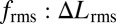 , increased dramatically as the amplitude of movement decreased (Fig. 5C). That is, the nodal point controller, compared with the unidirectional wave controller, renders the system increasingly more maneuverable as movement amplitude decreases, confirming our hypothesis (Fig. 5C). Using the validated computational model, the nodal point shift gain and damping constant corresponding to measured kinematics of Eigenmannia were also computed (SI Data and Discussion). Predicted control effort ratios for Eigenmannia, shown in Fig. 5C, reveal the same trend observed in biomimetic robot experiments. The offset between the fish and robot curves is explained by differences in kinematics and mechanical scale, most notably temporal frequency (Materials and Methods). Adopting a higher temporal frequency (with all other parameters constant) for each of the two inward-counterpropagating waves amplifies the nodal-shift gain (κ) (Fig. 4B). This would further amplify the advantage of counterpropagating waves in terms of maneuverability for low-amplitude tracking tasks.
Fig. 5.
Comparison of tracking performance using two different control strategies. (A-I and B-I) Control signals (blue, red, orange, and green) for counterpropagating waves  and a single traveling wave (f) are shown for four different reference trajectory amplitudes (A = 1 cm, 2 cm, 5 cm, and 7 cm, respectively). (A-II and B-II) Biomimetic robot positions (same color scheme) closely track the reference trajectories (black). (C) Ratio of the rms of the commanded control signals
  depends on the reference trajectory amplitude. The model predicts that this rms ratio tends to infinity as the reference amplitude, A, goes to zero, strongly favoring counterpropagating waves when the goal is stable hovering
  . Predicted and measured ratios for the robot closely match each other. Predicted ratios for Eigenmannia are based on traveling wave kinematics obtained during hovering (U = 0 cm/s). Uncertainty bars represent variability in kinematics of different subjects.
Discussion
A key insight of the Wright brothers was that an aircraft must be both sufficiently stable to maintain its flight path and simultaneously maneuverable enough to permit its control (ref. 32, chap. 1). How animals manage this seemingly inescapable tradeoff (34, 35) is an open question, especially because many swimming and flying animals appear to use locomotor strategies that are stable and yet facilitate the control of extraordinary maneuvers (4, 10). One possibility is that highly maneuverable animals are passively unstable, and stability is achieved solely via active feedback control using the nervous system (36).
By adopting a locomotor strategy that relies on the generation of antagonistic forces rather than a seemingly simpler strategy of moving the fin in either one direction or the other, the glass knifefish achieves a dramatic improvement in maneuverability, especially for small movements. This improvement in maneuverability is concurrent with, as shown above, a significant increase in damping that enhances passive stability, although perhaps not without some energetic cost (SI Data and Discussion). The fish could, in principle, actively stabilize itself using feedback control of either the nodal point (counterpropagating waves) or the frequency (single traveling wave). However, counterpropagating waves offer two advantages: They passively reject perturbations (increased passive stability) and also require substantially lower control effort (increased maneuverability). Therefore, antagonistic forces eliminate the tradeoff between passive stability and maneuverability.
This strategy, which was discovered in measurements of the weakly electric fish Eigenmannia and tested using a biomimetic robot and a computational model, may confer the same benefit in other animals that use antagonistic forces for locomotor control. Small terrestrial animals with a sprawled biomechanical posture appear to generate large lateral forces during forward running that have been postulated to enhance stability and maneuverability (5), although it remains unclear how such forces scale with body size. A mathematical model of high-frequency flapping flight suggests that the antagonistic forces generated by the opposing movements of wings may similarly increase both maneuverability and stability (4). It is interesting to note that high-frequency flapping fliers necessarily generate mutually opposing forces; that is, they cannot readily turn these forces off during hovering. Eigenmannia, by contrast, are ideal for studying the role of mutually opposing forces because in these fish, such forces result from a neural strategy rather than a biomechanical constraint.
Mounting evidence suggests that the passive design of animal morphology facilitates control, thereby reducing the number of parameters that must be managed by the nervous system (37, 38). Here, we describe a dynamical system that facilitates control by incorporating a similar design principle. Counterpropagating waves, which paradoxically appear to be a more complex behavioral strategy than the generation of simpler unidirectional waves, nevertheless simplify locomotor control. First, this strategy enhances stability and maneuverability as we have shown. Second, modulation of the speed and direction of a single traveling wave requires simultaneous (and instantaneous) coordination across a distributed network of spinal circuits, whereas modulation of the nodal point of two ongoing counterpropagating waves permits control via the coordination of a small number of these segmental circuits. How this motor coordination is achieved in the animal remains an open and interesting question (39). Nevertheless, these data suggest that the dynamic design of animal morphology and its attendant neural systems are tuned (5, 8, 40, 41) for simplified task-level control.
Materials and Methods
Experimental Apparatus.
A schematic of the experimental setup is shown in Fig. 2A. An electric pump circulates water in the flow tunnel. A refuge machined from a 15-cm segment of 2-inch diameter PVC pipe was mounted parallel with the flow in the middle of the test section. The bottom half of the pipe was removed to allow the fish to be video-recorded through a window on the bottom of the test section. The refuge was positioned far enough away from the bottom of the tank to avoid boundary layer effects. A high-speed camera captured video from below (more details are provided in SI Materials and Methods).
Biological Experiments.
Adult E. virescens, obtained through commercial vendors, were housed in community tanks. Experiments were performed in the custom flow facility described above. In both the flow facility and housing tanks, water temperature was maintained at ∼25–27 °C, and conductivity was ∼150–250 μS/cm. All experimental procedures were reviewed and approved by the Johns Hopkins University Animal Care and Use Committee and follow guidelines established by the National Research Council, the Society for Neuroscience, and previously established methodologies (42).
Individual fish (n = 5) were placed in the test section of the flow tunnel. Without training, the fish tend to swim into and stay inside the PVC tube (7, 8). When we varied the steady-state flow speed, the fish typically remained stationary relative to the refuge. A single trial consisted of a fish remaining stationary in the tube by swimming forward (into the flow) at the flow speed. Trials were conducted at flow speeds from 0 to 12 cm/s in 1.5-cm/s increments. The order of these nine trials was pseudorandomized, and three replicates (sets) of trials were collected for each individual, totaling 27 experiments per fish. Note that we only examined forward swimming for experimental convenience, because the fish often tend to reorient themselves into the flow. However, the fish readily swim both forward and backward when tracking a refuge (8, 9), and when they do swim backward, the nodal point shifts rostral to its zero position as expected (Movie S3).
For each trial, data were collected for several seconds. Using open source code (43) written for MATLAB (MathWorks, Inc.), the overall fore–aft position of the fish was tracked from the video. One second of data (100 frames) of steady-state swimming was selected by inspection of the position plotted as a function of time. This 1 s of data was used to quantify the kinematic parameters of both the rostral and caudal traveling waves. The nodal point, positions of both ends of the fin, and peaks and troughs of the fin were manually digitized for each trial (Fig. 2B). The fin height profile,  , was digitized for each individual fish (Fig. S2) for use in the computational fluid model below; fish were lightly anesthetized in buffered MS222 (0.2 g/L Tricaine-S; Western Chemical, Inc.) for photography.
These data were postprocessed using a custom MATLAB script to compute the rostrocaudal nodal shift, wavelength, frequency, and amplitude of angular deflection of the two waves. For each trial, amplitude of angular deflection was fitted for each wave assuming it remains constant for all rays along each half of the fin.
Computational Model.
We approximated the fin kinematics using two sinusoidal traveling waves, as is standard for unidirectional waves (21, 28). The angle, θ, between each fin ray and the sagittal plane oscillates, and the relative phase changes along the rostrocaudal axis, producing a traveling wave, modeled as a sinusoid:
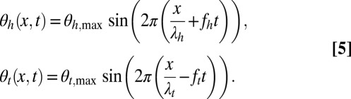 |
Subscripts h and t stand for head and tail waves, respectively; x denotes the coordinate along the rostrocaudal axis;  and
and  are the head and tail wavelengths, respectively; and fh and ft are the head and tail frequencies, respectively, of fin oscillation. The kinematic parameters are depicted in Fig. 1C.
The computational model used in this paper is based on a fluid drag model (26, 27).* The model applies to flow regimes with a high Reynolds number and neglects the fluid interaction. Under the conditions of the experiment, the Reynolds number  can be estimated in the range of 103 to 104 (
 ,
,  , for
, for  ). Drag force applied to the propulsive infinitesimal element is given by:
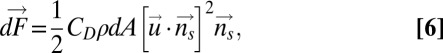 |
where CD is the coefficient of the drag depending on the shape ( in this study, evaluated from robotic experiments), ρ is the density of the fluid, dA is the area of the infinitesimal element, and
  is the unit normal to the surface at the centroid of the infinitesimal element. Details of how this model is used to estimate the nodal point gain (Eq. 1) and damping constant (Eq. 2) for Eigenmannia, and how it leads to the plant model shown in Eq. 4, are provided in SI Materials and Methods.
Biologically Inspired Robotic Fin Experiments.
We used a biomimetic knifefish robot (29, 31) to measure forces generated by counterpropagating waves as well as to assess freely swimming control strategies in one dimension. Mechanical design constraints limited us to a larger length scale and longer time scale than Eigenmannia. The fin consisted of 32 individually actuated rays and measures 32.60 cm in length and 3.37 cm in depth. Fig. S1A shows a schematic of the force experiments, where the robot is suspended from an air-bearing platform from above. The platform was rigidly attached to mechanical ground through a 9-N single-axis force sensor (Futek Advanced Senor Technology) along the fore–aft axis. The robot was fixed in all other translational and rotational axes. The working section of the flow tunnel was 80 cm long, 22 cm wide, and 28 cm deep.
In the first set of force measurements, we varied the nodal point of counterpropagating waves along the fin from −8.15 cm to 8.15 cm in increments of 1.63 cm (0 cm indicates the middle of the fin) while the robot was suspended in still water. Force measurements were gathered at 1,000 Hz and averaged over 5 s after initial transients had dissipated. In the second set of force measurements, we varied the flow speed of the water tunnel from 0 to 10 cm/s in increments of 0.5 cm/s while keeping the nodal point of the counterpropagating waves fixed at 0 cm (in the middle of the fin). To test sensitivity to other kinematic parameters, we repeated both sets of force experiments with varied frequencies and angular amplitudes as shown in Tables S1 and S2.
For fore–aft trajectory tracking experiments, we removed the force sensor to allow the robot to swim freely forward and backward, as shown in Fig. S1B. A linear encoder provided feedback on the position of the robot along the fore–aft axis of the water tunnel. At a cycle rate of 10 Hz, a microcontroller gathered this position feedback, derived robot velocity, calculated the control signal based on the control law described previously (linear quadratic controller), and sent the control signal over a serial line to the microcontroller dedicated to control of the robot rays. Position, time, and the control signal were logged for later analysis.
Supplementary Material
Acknowledgments
We thank Allison Tse, Rachel Jackson, and Rohan Ramesh for help in digitizing preliminary data. This material is based on work supported by the National Science Foundation under Grants 0543985, 0941674, and 0845749 and by the Office of Naval Research under Grant N000140910531.
Footnotes
The authors declare no conflict of interest.
This article is a PNAS Direct Submission. D.I.G. is a guest editor invited by the Editorial Board.
*Epstein M, Colgate JE, MacIver MA (2005) A biologically inspired robotic ribbon fin. Proceedings of the 2005 IEEE/RSJ International Conference on Intelligent Robots and Systems, Workshop on Morphology, Control, and Passive Dynamics.
This article contains supporting information online at www.pnas.org/lookup/suppl/doi:10.1073/pnas.1309300110/-/DCSupplemental.
References
- 1.Farley CT, Ko TC. Mechanics of locomotion in lizards. J Exp Biol. 1997;200(Pt 16):2177–2188. doi: 10.1242/jeb.200.16.2177. [DOI] [PubMed] [Google Scholar]
- 2.Full RJ, Tu MS. Mechanics of a rapid running insect: Two-, four- and six-legged locomotion. J Exp Biol. 1991;156:215–231. doi: 10.1242/jeb.156.1.215. [DOI] [PubMed] [Google Scholar]
- 3.Blickhan R, Full RJ. Similarity in multilegged locomotion: Bouncing like a monopode. J Comp Physiol A Neuroethol Sens Neural Behav Physiol. 1993;173(5):509–517. [Google Scholar]
- 4.Hedrick TL, Cheng B, Deng XY. Wingbeat time and the scaling of passive rotational damping in flapping flight. Science. 2009;324(5924):252–255. doi: 10.1126/science.1168431. [DOI] [PubMed] [Google Scholar]
- 5.Dickinson MH, et al. How animals move: An integrative view. Science. 2000;288(5463):100–110. doi: 10.1126/science.288.5463.100. [DOI] [PubMed] [Google Scholar]
- 6.Sprayberry JDH, Daniel TL. Flower tracking in hawkmoths: Behavior and energetics. J Exp Biol. 2007;210(Pt 1):37–45. doi: 10.1242/jeb.02616. [DOI] [PubMed] [Google Scholar]
- 7.Rose GJ, Canfield JG. Longitudinal tracking responses of the weakly electric fish, Sternopygus. J Comp Physiol A. 1993;171(6):791–798. [Google Scholar]
- 8.Cowan NJ, Fortune ES. The critical role of locomotion mechanics in decoding sensory systems. J Neurosci. 2007;27(5):1123–1128. doi: 10.1523/JNEUROSCI.4198-06.2007. [DOI] [PMC free article] [PubMed] [Google Scholar]
- 9.Roth E, Zhuang K, Stamper SA, Fortune ES, Cowan NJ. Stimulus predictability mediates a switch in locomotor smooth pursuit performance for Eigenmannia virescens. J Exp Biol. 2011;214(Pt 7):1170–1180. doi: 10.1242/jeb.048124. [DOI] [PubMed] [Google Scholar]
- 10.Webb PW. Stability and maneuverability. Fish Physiology. 2005;23:281–332. [Google Scholar]
- 11.Webb PW, Fairchild AG. Performance and maneuverability of three species of teleostean fishes. Can J Zool. 2001;79(10):1866–1877. [Google Scholar]
- 12.Full RJ, Kubow T, Schmitt J, Holmes P, Koditschek D. Quantifying dynamic stability and maneuverability in legged locomotion. Integr Comp Biol. 2002;42(1):149–157. doi: 10.1093/icb/42.1.149. [DOI] [PubMed] [Google Scholar]
- 13.Emerson SB, Koehl MAR. The interaction of behavioral and morphological change in the evolution of a novel locomotor type: “Flying” frogs. Evolution. 1990;44(8):1931–1946. doi: 10.1111/j.1558-5646.1990.tb04300.x. [DOI] [PubMed] [Google Scholar]
- 14.Weihs D. Stability versus maneuverability in aquatic locomotion. Integr Comp Biol. 2002;42(1):127–134. doi: 10.1093/icb/42.1.127. [DOI] [PubMed] [Google Scholar]
- 15.Von Mises R. Theory of Flight. New York: Dover; 1959. [Google Scholar]
- 16.Marchaj CA. Aero-Hydrodynamics of Sailing. New York: Dodd, Mead; 1980. [Google Scholar]
- 17.Brandt SA. Introduction to Aeronautics: A Design Perspective. Reston, VA: AIAA; 2004. [Google Scholar]
- 18.Hedrick TL. Damping in flapping flight and its implications for manoeuvring, scaling and evolution. J Exp Biol. 2011;214(Pt 24):4073–4081. doi: 10.1242/jeb.047001. [DOI] [PubMed] [Google Scholar]
- 19.Jindrich DL, Full RJ. Many-legged maneuverability: Dynamics of turning in hexapods. J Exp Biol. 1999;202(Pt 12):1603–1623. doi: 10.1242/jeb.202.12.1603. [DOI] [PubMed] [Google Scholar]
- 20.Blake RW. Swimming in electric eels and knifefishes. Can J Zool. 1983;61(6):1432–1441. [Google Scholar]
- 21.Shirgaonkar AA, Curet OM, Patankar NA, MacIver MA. The hydrodynamics of ribbon-fin propulsion during impulsive motion. J Exp Biol. 2008;211(Pt 21):3490–3503. doi: 10.1242/jeb.019224. [DOI] [PubMed] [Google Scholar]
- 22.Ruiz-Torres R, Curet OM, Lauder GV, MacIver MA. Kinematics of the ribbon fin in hovering and swimming of the electric ghost knifefish. J Exp Biol. 2013;216(Pt 5):823–834. doi: 10.1242/jeb.076471. [DOI] [PubMed] [Google Scholar]
- 23.Albert JS. Species Diversity and Phylogenetic Systematics of American Knifefishes (Gymnotiformes, Teleostei). Division of Ichthyology, Museum of Zoology. Ann Arbor, MI: Univ of Michigan; 2001. [Google Scholar]
- 24.Lighthill J. Mathematical Biofluiddynamics. Philadelphia: Society for Industrial Mathematics; 1975. [Google Scholar]
- 25.Blake RW. Fish Locomotion. Cambridge, UK: Cambridge Univ Press; 1983. [Google Scholar]
- 26.Ekeberg Ö. A combined neuronal and mechanical model of fish swimming. Biol Cybern. 1993;69(5):363–374. [Google Scholar]
- 27.Sfakiotakis M, Lane DM, Davies JBC. Review of fish swimming modes for aquatic locomotion. IEEE Journal of Oceanic Engineering. 1999;24(2):237–252. [Google Scholar]
- 28.Lighthill J, Blake R. Biofluid dynamics of balistiform and gymnotiform locomotion. Part 1. Biological background, and analysis by elongated-body theory. J Fluid Mech. 1990;212(1):183–207. [Google Scholar]
- 29.Curet OM, Patankar NA, Lauder GV, MacIver MA. Aquatic manoeuvering with counter-propagating waves: A novel locomotive strategy. J R Soc Interface. 2011;8(60):1041–1050. doi: 10.1098/rsif.2010.0493. [DOI] [PMC free article] [PubMed] [Google Scholar]
- 30.Fry SN, Sayaman R, Dickinson MH. The aerodynamics of free-flight maneuvers in Drosophila. Science. 2003;300(5618):495–498. doi: 10.1126/science.1081944. [DOI] [PubMed] [Google Scholar]
- 31.Curet OM, Patankar NA, Lauder GV, MacIver MA. Mechanical properties of a bio-inspired robotic knifefish with an undulatory propulsor. Bioinspir Biomim. 2011;6(2):026004. doi: 10.1088/1748-3182/6/2/026004. [DOI] [PubMed] [Google Scholar]
- 32.Astrom KJ, Murray RM. Feedback Systems: An Introduction for Scientists and Engineers. Princeton: Princeton Univ Press; 2008. [Google Scholar]
- 33.Lewis FL, Syrmos VL. Optimal Control. New York: Wiley; 1995. [Google Scholar]
- 34.Kitano H. Biological robustness. Nat Rev Genet. 2004;5(11):826–837. doi: 10.1038/nrg1471. [DOI] [PubMed] [Google Scholar]
- 35.Csete ME, Doyle JC. Reverse engineering of biological complexity. Science. 2002;295(5560):1664–1669. doi: 10.1126/science.1069981. [DOI] [PubMed] [Google Scholar]
- 36.Smith JM. The importance of the nervous system in the evolution of animal flight. Evolution. 1952;6(1):127–129. [Google Scholar]
- 37.Collins S, Ruina A, Tedrake R, Wisse M. Efficient bipedal robots based on passive-dynamic walkers. Science. 2005;307(5712):1082–1085. doi: 10.1126/science.1107799. [DOI] [PubMed] [Google Scholar]
- 38.Full RJ, Koditschek DE. Templates and anchors: Neuromechanical hypotheses of legged locomotion on land. J Exp Biol. 1999;202(Pt 23):3325–3332. doi: 10.1242/jeb.202.23.3325. [DOI] [PubMed] [Google Scholar]
- 39.Ting LH, Macpherson JM. A limited set of muscle synergies for force control during a postural task. J Neurophysiol. 2005;93(1):609–613. doi: 10.1152/jn.00681.2004. [DOI] [PubMed] [Google Scholar]
- 40.Snyder JB, Nelson ME, Burdick JW, MacIver MA. Omnidirectional sensory and motor volumes in electric fish. PLoS Biol. 2007;5(11):e301. doi: 10.1371/journal.pbio.0050301. [DOI] [PMC free article] [PubMed] [Google Scholar]
- 41.Hedrick TL, Robinson AK. Within-wingbeat damping: Dynamics of continuous free-flight yaw turns in Manduca sexta. Biol Lett. 2010;6(3):422–425. doi: 10.1098/rsbl.2010.0083. [DOI] [PMC free article] [PubMed] [Google Scholar]
- 42.Hitschfeld EM, Stamper SA, Vonderschen K, Fortune ES, Chacron MJ. Effects of restraint and immobilization on electrosensory behaviors of weakly electric fish. ILAR J. 2009;50(4):361–372. doi: 10.1093/ilar.50.4.361. [DOI] [PMC free article] [PubMed] [Google Scholar]
- 43.Hedrick TL. Software techniques for two- and three-dimensional kinematic measurements of biological and biomimetic systems. Bioinspir Biomim. 2008;3(3):034001. doi: 10.1088/1748-3182/3/3/034001. [DOI] [PubMed] [Google Scholar]
Associated Data
This section collects any data citations, data availability statements, or supplementary materials included in this article.