Abstract
Protection of public and military personnel from chemical and biological warfare agents is an urgent and growing national security need. Along with this idea, we have developed a novel class of fiber optic chemical sensors, for detection of toxic and biological materials. The design of these fiber optic sensors is based on a cladding modification approach. The original passive cladding of the fiber, in a small section, was removed and the fiber core was coated with a chemical sensitive material. Any change in the optical properties of the modified cladding material, due to the presence of a specific chemical vapor, changes the transmission properties of the fiber and result in modal power redistribution in multimode fibers. Both total intensity and modal power distribution (MPD) measurements were used to detect the output power change through the sensing fibers. The MPD technique measures the power changes in the far field pattern, i.e. spatial intensity modulation in two dimensions. Conducting polymers, such as polyaniline and polypyrrole, have been reported to undergo a reversible change in conductivity upon exposure to chemical vapors. It is found that the conductivity change is accompanied by optical property change in the material. Therefore, polyaniline and polypyrrole were selected as the modified cladding material for the detection of hydrochloride (HCl), ammonia (NH3), hydrazine (H4N2), and dimethyl-methl-phosphonate (DMMP) {a nerve agent, sarin stimulant}, respectively. Several sensors were prepared and successfully tested. The results showed dramatic improvement in the sensor sensitivity, when the MPD method was applied. In this paper, an overview on the developed class of fiber optic sensors is presented and supported with successful achieved results.
Keywords: Fiber Optic Sensors, Chemical Sensors, Biological Sensors, Home Land Security, Fiber Optics, Gas Sensors, Sarin Detection
1. Introduction
Optical and fiber optic chemical sensors have been reported extensively in literatures since 1970's. Fiber optic sensors have since then found applications in chemical [1-4], biochemical [4-8], biomedical and environmental [9-12] sensing.
In general, Fiber optic sensors are classified as intrinsic and extrinsic type sensors. In the extrinsic type of sensors the optical fiber is only used as a means of light transport to an external sensing system i.e. the fiber structure is not modified in any way for the sensing function. Examples of extrinsic fiber optic sensors include fibers terminated in active layers e.g. optode [13], fibers having end face mirrors or fibers confronting other transducer elements or fibers [14]. The intrinsic fiber optic sensors differ form extrinsic sensors, where light does not have to leave the optical fiber to perform the sensing function. In the intrinsic fiber optic sensors, the optical fiber structure is modified and the fiber itself plays an active role in the sensing function. Examples of intrinsic fiber sensors include, fibers with Bragg gratings, modified claddings or micro or macrobends.
Fiber optic intrinsic sensors provide numerous advantages over conventional sensors, which include immunity to electromagnetic interference, small and compact size, sensitivity, remote sensing, ability to be multiplexed and the ability to be embedded into various textile structures [15]. Internsic sensors have the characteristics of high sensitivity, selectivity, and reliability and can perform measurements in specific-sites and real-times. Organic conducting polymers (OCP's) such as Polypyrrole, Polyaniline, Polypthiophene, Polyindoles, Polyacetylenes on the other hand have a unique ability to show a reversible change in their electrical resistance and optical properties when exposed to certain toxic vapors. These conducting polymers are easy to prepare and show excellent ambient stability and very rapid and reversible absorption kinetics. They have, therefore, attracted much attention in the area of gas sensing. The developed class of fiber optic sensors combined the advantages of optical fibers and conducting polymers with high sensitivity and easy processibility for sensing hydrochloric acid, ammonia, hydrazine, and nerve agent sarin stimulant organophosphate dimethyl-methylphosphonate.
The developed class of fiber optic intrinsic sensors was based on the modified cladding approach [16-20]. The passive cladding of the optical fiber was removed form a small section and replaced by a chemo-chromic material. Any change in the complex refractive index of the material due to the presence of the analytes, changes the transmission properties of the optical fiber. The R&D work is conducted in four major steps or tasks: i) selection and characterization of the chemical sensitive material, such as Polyaniline and Polypyrrole, ii) design of the optical fiber sensing element, iii) development of optical fiber modification process, and iv) fiber optic sensor characterization and optimization.
The fiber optic sensors were tested for its sensitivity towards vapors of HCl and ammonia, in the case of using Polyaniline as the modified cladding, and vapors of DMMP, Hydrazine and Hydrogen peroxide in the case of using Polypyrrole as the modified cladding. Using total light intensity modulation method, the sensors showed very reasonable responses. However, the Modal Power Distribution (MPD) technique indicated further improvement of the sensor sensitivity, which is caused by the more interaction of higher order modes at the core/cladding interface.
2. Selection and characterization of chemo-chromic conducting polymers i.e. Polyaniline and Polypyrrole
Polyaniline and Polypyrrole represent a class of conducting polymer. In this type of polymers, electrical conductivity is achieved by creating charge carriers through a p-type (holes) or an n-type (electrons) doping of the conjugated polymer backbone. These conducting polymers can be doped by a variety of redox processes [21] i.e. chemical or electrochemical partial oxidation or partial reduction. There is also evidence of non-redox doping process [22]. The doping/dedoping process mentioned above results in reversible or irreversible changes in electrical and optical properties of these conducting polymers, hence these materials have found applications in electrochromic devices and optical chemical sensors. A large number of gas sensors make the use of conducting polymers as their sensing elements since they have great design flexibility and are very stable at ambient temperature and pressure. Conductivity and work function of conducting polymers are the two main properties that are used in chemo-electric, chemo-mechanic or chemo-chromic transduction [23, 24].
2.1. Polyaniline
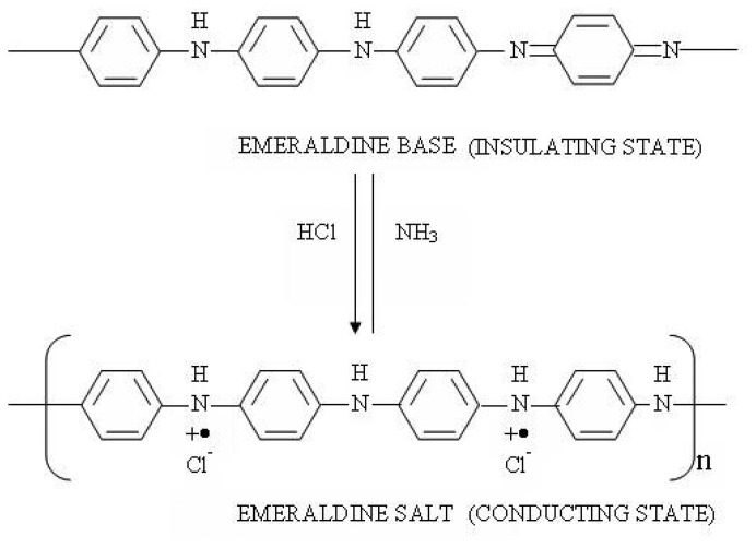
Polyaniline (emeraldine base) has the following composition and consists of alternating reduced and oxidized repeat units. Polyaniline can be switched back and forth from its insulating state to the conducting state by doping with HCl solution or vapor and de-doping with ammonium hydroxide solution or vapor, respectively, as shown in Figure 1. This change is accompanied with the optical property change also. Therefore, polyaniline was used as the modified fiber cladding material for sensing HCl vapor and NH3. Thin film coating of 400nm thickness, using in-situ deposition, was used in our application.
Figure 1.
Switching between emeraldine base (insulating form) and emeraldine salt (conducting form) by HCl and ammonia, respectively.
2.2. Polypyrrole
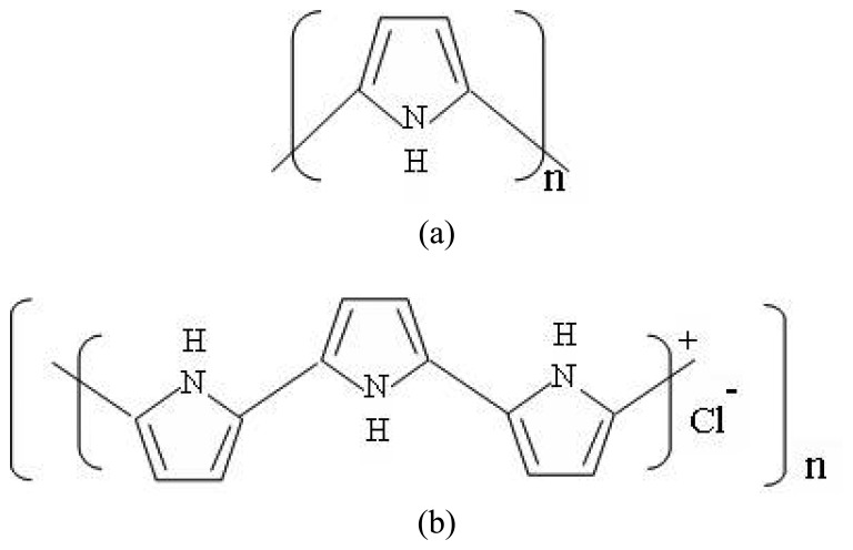
The base unit of polypyrrole is pyrrole, the structure of which is a five membered heteroaromatic ring containing a nitrogen atom as shown in Figure 2a. Polypyrrole is synthesized from the pyrrole monomer by mild oxidation, using chemical or electrochemical technique. After the oxidation of the monomer a black solid polymer is precipitated from the solution, the polypyrrole structure in its oxidized form is shown in Figure 2b. Film thicknesses of the order of 1-1.5 μm, using in-situ deposition, were obtained for our application.
Figure 2.
a) Polypyrrole structure and b) Polypyrrole structure in its oxidized form.
2.3. Thin film characterization
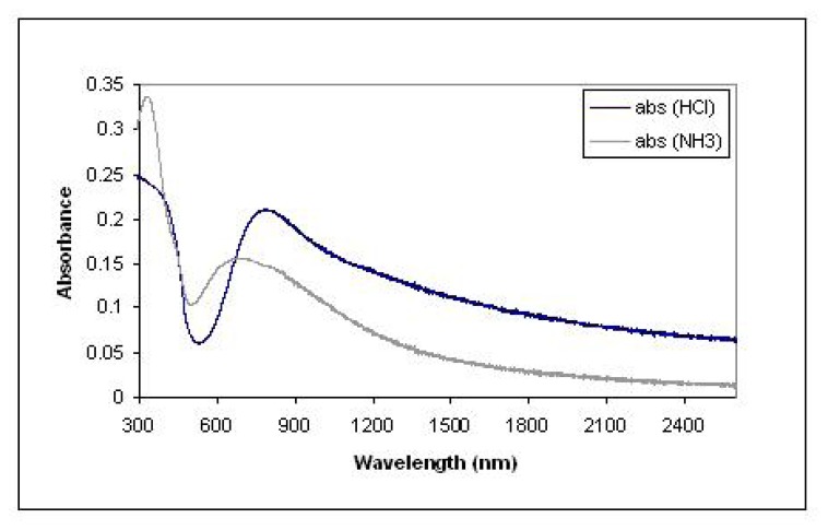
For a polyaniline film, the light absorption measurements were conducted after the film was exposed to HCl and NH3 vapors, respectively, as shown in Figure 3[20]. The difference of the spectra indicated that HCl and NH3 vapors induced a different band structure and conformation of the polymer. Therefore, the optical property of the film changed when the film switches from one state (doped by HCl) to another (de-doped by NH3). The refractive index measurement by ellipsometry showed that the refractive index changed from 2.43 (doped by HCl) to 1.95 (de-doped by NH3).
Figure 3.
Polyaniline film response to Ammonia and HCl
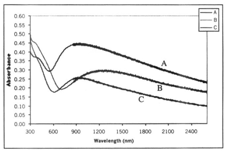
For a polypyrrole film [20], the measurements were conducted before and after the film was exposed to hydrazine (N2H4) and hydrogen peroxide (H2O2), as shown in Figure 4. The refractive indices are 1.82 (before exposure to hydrazine) and 1.71 (after exposure to hydrazine).
Figure 4.
Polypyrrole response to A-as deposited, B- after exposure to hydrazine, C- after exposure to hydrogen-peroxide.
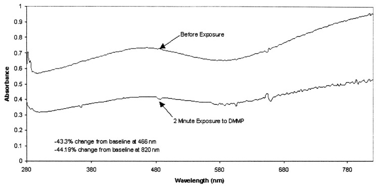
A change in absorbance is reported in polypyrrole thin films, exposed to DMMP [25]. As shown in Figure 5, a 40% reduction occurred in the UV/Vis absorbance band. It is reported that the DMMP interacts electronically with the polypyrrole to increase the amount of free mobile hole charge carriers [23]. Also, additional drop in the resistance of polypyrrole thin films can be achieved when is doped with Naphtalene-disulphonic acid (NDSA), before exposure to DMMP vapor [23]. The change in resistivity implies a change of the refractive index of the polypyrrole. A change in the refractive index and absorbance of the modified cladding will lead to a change in the propagation of the light through the sensing element which results in optical intensity modulation. The optical property change in both polymer films are attributed to changes in bulk conductivity and absorbance properties.
Figure 5.
Polypyrrole film response to DMMP.
3. Design of fiber sensing element
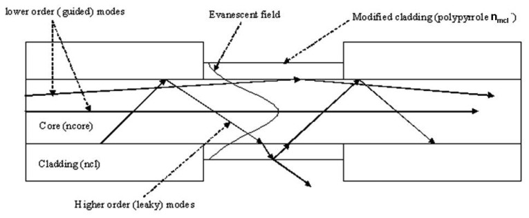
The optical fiber sensors were developed based on the modified cladding (or coating) design [16, 17]. The passive cladding of the optical fiber is removed from a small section and is replaced by a chemo-chromic material as shown in Figure 6. The refractive index is a complex quantity given by
| (1) |
Figure 6.
Schematic of the optical fiber sensor design showing the modified cladding region.
Where
ncomplex complex refractive index of a material
nreal real part of the refractive index
k imaginary part related to the absorbance of the material.
Any change in the real refractive index or the absorbance of the material due to the presence of the analyte changes the transmission properties of the optical fiber. There can be three different modes of operation (cases 1-3 next) of the sensor depending upon the refractive index of the modified cladding (nmcl), i.e. the chemo chromic material, relative to the refractive index of the core (ncore) and the refractive index of the original cladding (ncl). For example, polypyrrole film refractive index is 1.817 [20] which is much higher than the core refractive index 1.45, and the sensor operation is in the leaky mode principles i.e. case 2 below.
Case 1: Operations on the evanescent mode principles (ncl = nmcl < nco)
In this case since the refractive index of the modified cladding is equal to that of the original cladding the wave-guiding conditions do not change in the modified region and the light has the same Gaussian intensity profile throughout the fiber. There is an evanescent field penetration in the modified region, as shown in Figure 6. Any change in the absorbance of the material will result in evanescent absorption which will lead to intensity modulation.
Case 2: Operations on the leaky mode principles (nmcl >nco>ncl)
Since this condition does not satisfy total internal reflection at the interface between the core and the modified cladding therefore, guided modes will be changed to leaky modes in the modified region, as shown in Figure 6. The boundary between the air and the modified cladding can support total internal reflection and some of the light will propagate in the modified cladding and some is reflected back into the core. Any change in the complex refractive index of the modified cladding due to the analyte can change the waveguide transmission conditions and result in an intensity change.
Case 3: Operations on the partial leaky mode principles (ncl < nmcl < nco)
In this case the sensor operates in the partial leaky mode i.e. the critical angle in the modified region is higher than the critical angle for the fiber, so some higher order modes will leak through the modified cladding and the lower order modes will continue as guided modes. Any change in the real part or the complex part (absorbance) of the refractive index can lead to a change in the transmitted intensity.
4. Development of detection techniques - Modal Power Distribution
Current research in fiber optic sensors relates perturbations to change in the total intensity of the light signal transmitted through the optical fiber. Other methods involve launching coherent polarized light through an optical fiber and observing the changes in the polarization or phase of the launched signal with the applied external perturbation. Sensors based on total intensity modulation are simple and cost effective. However, they provide limited sensitivity. Phase and polarization modulation type sensors provide much better sensitivity but they are bulky and require laser sources and expensive techniques for detection. To overcome these limitations, a novel technique, based on monitoring the Modal Power Distribution (MPD) in multimode fibers, was developed. This technique provides a sensitive and inexpensive methodology for miniature sensors applications [26, 27].
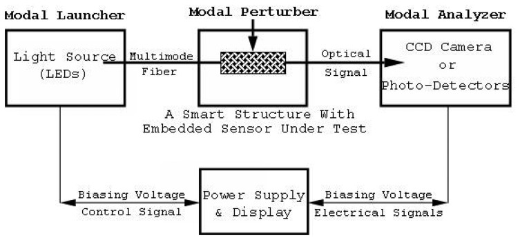
The principle of operation of the developed technique is based on Spatial Intensity Modulation (SIM) of the modal power in multimode fibers. Within a multimode optical fiber, optical signals propagate according to the modal structure of the fiber and the boundary conditions. Altering the boundary conditions of an optical fiber induces modal coupling and results in Modal Power Distribution (MPD) modulation. The Coupled-Mode-Theory can be employed for the analysis of the MPD modulation [18, 19, 28, 29]. The MPD within a multimode fiber is a function of the geometry (size) and the optical properties (core and cladding indices) of the fiber and the light launching conditions. Deforming the fiber by mechanical stresses or other forms of perturbation results in modal power modulation, which can be exploited in sensing the applied signals. The measurements of the distribution and the subsequent redistribution of the modal power can be accomplished by scanning the far-field pattern at the fiber end using a CCD camera, or by using one or more photodetectors positioned at a specific location in the far-field zone, as shown in Figure 7. The modal launcher is a single or array of LEDs, used to excite a limited group of modes within the optical fiber, and the modal analyzer is the detection system of the modal power positioned at the output end of the optical fiber, in the far-field zone.
Figure 7.
The general block diagram of the developed characterization method.
As an example, a step index silica fiber of 100□)m diameter was excited at 10 degrees off-axis. The 2-D far-field pattern (MPD; and intensity profile were scanned and recorded by a CCD camera as shown in Figure 8(a). When the fiber was under stress, the recorded far-field pattern shows inter-modal coupling and redistribution of the modal power Figure 8(b). As the applied stress was increased, considerable rearrangement of the modal power was recorded in a similar way. These two figures indicate that continuous variation of the applied perturbation will result in a respective change in the MPD, in a very sensitive manner. For a cost effective and miniature sensor configuration, the CCD camera can be replaced by a 1-D array of photodetectors located at the radial positions in the far-field. These detectors can be coupled to simple biasing and signal processing circuits to indicate the spatial variation in the optical signal. Using a light emitting diode as the optical source and regular photodiodes for detection will provide a miniature and inexpensive technique compared to the phase or polarization modulation techniques.
Figure 8.
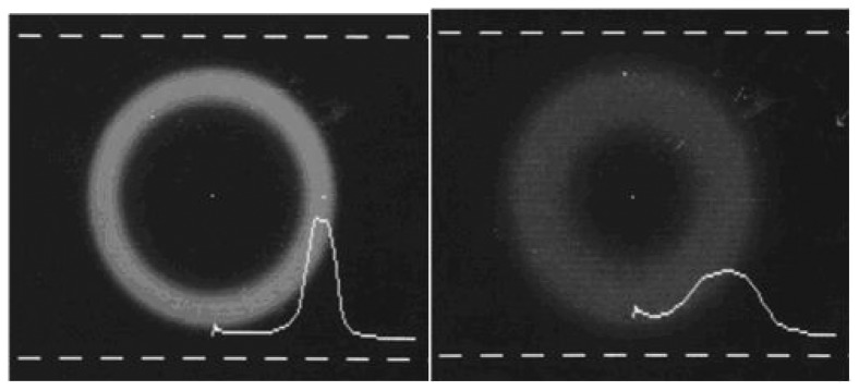
The 2-D image and the horizontal intensity profile of the far-field pattern measured at the center before (a) and after (b) the presence perturbation.
The sensitivity and the dynamic range of this type of sensors are related to the modal structure of the fiber, and to the behavior of the materials surrounding it. A properly coated optical fiber can offer better performance over that of the bare fiber. Therefore, a compatible method suitable for sensors applications has been developed. Experimental and theoretical feasibility studies show that the developed sensing technique is sensitive, inexpensive, and can be manufactured in microstructure components.
5. Application of conducting polymers as the fiber modified cladding
The modification of the optical fiber involves two major steps for chemical sensor application [20, 30], (a) removal of the passive cladding (fiber etching), and (b) application of active cladding (fiber coating). An all silica multimode fiber with core/cladding/jacket dimension of 105/125/250 μ m was selected for such application.
5.1. Fiber etching
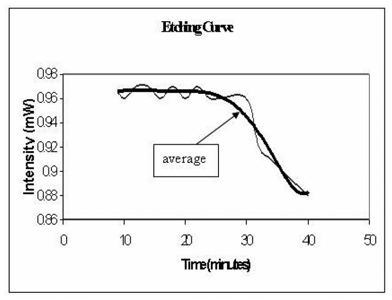
A meter length of optical fiber was used and a small section (1cm) of the jacket was stripped off the center of the optical fiber. The exposed section of the fiber is immersed in HF (hydrofluoric acid) solution which etches and removes the glass cladding of the optical fiber. The etching process is performed under real-time monitoring, as shown in the experimental set-up, Figure 9. While the fiber is immersed in the etching solution (HF), the fiber is connected to a He-Ne (wavelength 633 nm) light source and a Silicon photo-detector (Newport 818 SL wavelength range 400-1100 nm) and the power is continuously monitored. The optical power transmitted through the fiber remains constant as long as the glass cladding thickness is larger than the evanacent field penetration. There is a sudden drop in the power as the cladding is very thin or completely removed, as seen in the etching plot in Figure 10. A concentration of 16.3% HF takes 30 min to etch away a 10 micron thick cladding.
Figure 9.
Schematic drawing of the fiber etching setup.
Figure 10.
Light intensity as the fiber cladding etched away in 16.33% HF solution.
The etching process has been calibrated to prevent the core from being etched. This was done by repeating the process for a 16.3% HF acid concentration at different times and measuring the diameter of the fiber using optical microscopy. Once this calibration has been achieved a fixed acid concentration and a fixed time of etching is able to give exact core diameter, which is confirmed for each sample using optical microscopy.
5.2. Coating conducting polymers on optical fibers
Several techniques, such as casting, spin-casting, and in-situ deposition methods, are available to produce polyaniline and polypyrrole thin films. Both spin-cast and in-situ deposition methods were used to coat the cladding-removed fiber region with the conducting polymers [20, 30, 31]. For spin-cast method, the spinning time, spin-rate, and the viscosity of the solution have to be properly controlled to get a uniform thin film. For in-situ deposition method, the polymerization process and fiber deposition time have to be determined to obtain a homogeneous coating.
6. Sensor response to chemical vapors
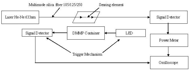
The coated optical fiber, i.e. the sensing element, is integrated with a He-Ne (wavelength 633 nm) light source and a Silicon photo-detector (Newport 818 SL wavelength range 400-1100 nm). The complete experimental set up is shown in Figure 11. The sensing element is exposed to the analyte vapor. The output intensity is recorded by a power meter (Newport 1815C power range 20 nW-2 kW), which is connected to an oscilloscope for real time measurement. The Trigger mechanism consists of a LED - detector combination which cuts the light to the detector during the analyte exposure period. The sensor response time is measured as the time lapse between the trigger and the beginning of intensity drop in the fiber.
Figure 11.
Experimental set-up for sensor testing.
6.1. Sensing HCl and NH3 vapors
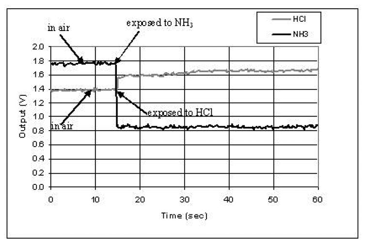
When polyaniline was used as the modified cladding layer, HCl and NH3 vapors could be detected immediately upon their exposure to the fiber sensing region. It is known that polyaniline can be easily doped by acid (such as HCl) and de-doped by base (such as NH3). The doping process and de-doping process are reversible. It was found that after the polymer was doped, it was stable in the air. However, after the de-doping chemical was moved away, the polymer gradually returned to the doped state. The polyaniline was doped after in-situ deposition. The optical property of polyaniline changes from the doped state to the de-doped state. Therefore, when the sensing region of the optical fiber, which was coated with polyaniline, was exposed to acid vapor (HCl) or base vapor (NH3), the output intensity of optical signal changed. Figure 12 showed the sensor output change when it was exposed to the chemical vapors. The signal response (R) is calculated based on the following equation:
| (2) |
Figure 12.
Sensor response to chemical vapors of HCl and NH3. The sensing fiber was coated polyaniline by in-situ deposition. The deposition time was 30 minutes.
Where
Iout is the average light intensity before gas exposure
I'out is the average light intensity after gas exposure
The response is 50% for NH3 vapor and 12% for HCl vapor, respectively.
In Figure 12, at the time of 15 seconds, the sensing fiber was exposed to NH3 vapors, which induced the power dropped from 1.75V to 0.87V. After 60 seconds, the NH3 vapor was moved away. It was found that the polyaniline partially went back to the HCl doped state with the output power increased to 1.4V. Then the sensor was exposed to HCl vapor, which resulted in the power increase by 12%. More experiments indicated that the response of sensing signal did not show significant influence by film deposition time from 7 to 30 minutes, however, any imperfections in the structure of the deposited layer can decreased the signal response of the sensor.
6.2. Sensing hydrazine vapor
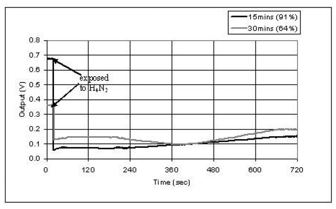
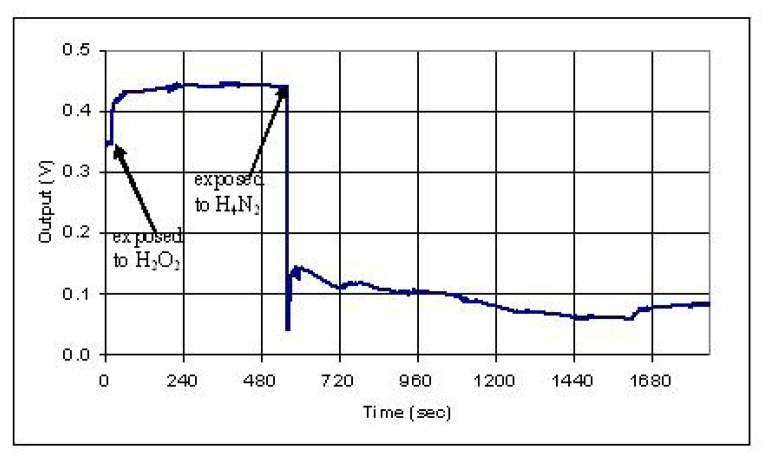
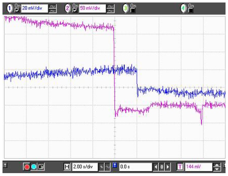
Polypyrrole was used as the modified cladding layer to detect hydrazine vapor. The sensing fiber was coated polypyrrole by in-situ deposition. The deposition time was 15 and 30 minutes, respectively. When hydrazine vapor was exposed to the sensing region, the optical signal decreased (based on Eq.2) 91% and 64% for 15 and 30 minute deposited samples, respectively, as shown in Figure 13. The difference of the response may be induced by the thickness, uniformity, and conformation of the polymer layer. After the polypyrrole region was exposed to Hydrazine, it was exposed to hydrogen peroxide vapor and hydrazine vapor again as shown in Figure 14. The output increased by hydrogen peroxide vapor to 28% and decreased by hydrazine vapor to 86%. It was found that the sensor can only be used for a few times, since an irreversible change occurred in polypyrrole after it was exposed to hydrazine.
Figure 13.
Sensor response to chemical vapor of hydrazine (H4N2).
Figure 14.
Sensor response to chemical vapors of hydrogen peroxide (H2O2) and hydrazine (H4N2).
6.3. Sensing DMMP vapors
The sensor response to DMMP vapor exposure (without any added dopant) is shown in the Figure 15. A percentage response of approximately 2.1% was obtained. This response is attributed to the leaking of the higher order modes through the modified cladding of the fiber, due to the increased conductivity in polypyrrole film due to DMMP adsorption. The response was calculated using the Equation (2).
Figure 15.
Sensor response for polypyrrole coated fiber upon DMMP exposure.
To enhance the response of polypyrrole sensor towards DMMP, acid dopants were added to the polypyrrole structure. The rational for doping polypyrrole was to introduce secondary doping sites for DMMP in the structure. Secondary doping sites are sites where an interaction with DMMP would lead to conformational change in the polyprrole structure leading to an optical property change.
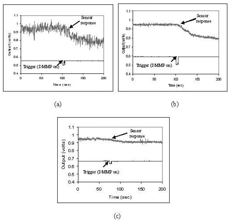
To improve the response to DMMP, several sensors were prepared, by coating the sensing part of the fiber with differently doped polypyrrole. Three different dopants i.e. HCl, NDSA & ASQA were added during the polymerization stage, during the synthesis of Polypyrrole. Optical fiber samples were coated for 5 min by in-situ deposition. The concentration of the dopant acid is varied (0.1ml, 0.5ml, 1ml, 1.5ml of 1Molar (M) dopant solution in 100ml oxidant solution) to investigate the influence of doping concentration on the sensor response. The choice of the three particular dopants is made on the bases of their reported sensitivities to DMMP [23]. Figures 16(a-c) are the waveforms obtained for 0.5ml of HCl, NDSA & ASQA doping to polypyrrole respectively.
Figure 16.
Sensor Response of Doped Polypyrrole for (a) HCL, (b) NDSA, and (c) ASQA dopants.
The upper waveform is the sensor response and the lower waveform is the trigger i.e. the start of the exposure of DMMP. It can be seen that the doping polypyrrole results in a dramatic change in the percentage sensor response form just 2.1% for undoped polypyrrole to 15.75% for HCl, 15.75% for NDSA doped and 4.21% for ASQA doped polypyrrole. This increase in the sensor response to DMMP in doped polypyrrole may be attributed to conformational changes which may come about in doped polypyrrole due to DMMP adsorption [23, 32]. These conformational changes may further increase the conductivity change upon DMMP exposure, resulting in an enhanced sensor response.
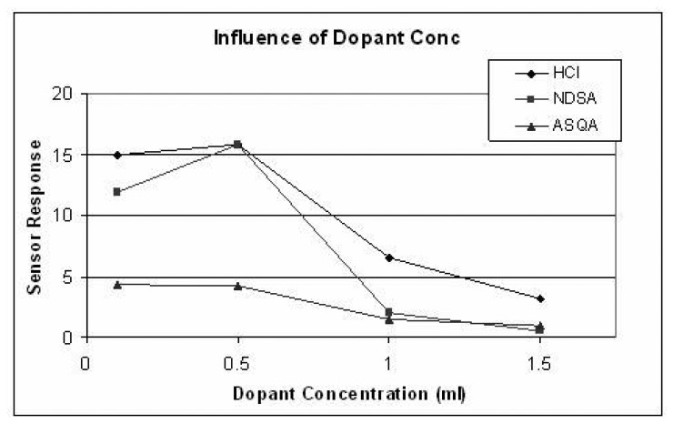
It is found that as the amount of dopant is increased the sensor response in the case of HCl and NDSA increases up to 0.5ml of 1M concentration and decreases as the dopant amount is increased further, as shown in Figure 17. For ASQA doping, the sensor response is almost constant up to 0.5ml dopant concentration and then there is a gradual decrease observed, with increasing dopant concentration, Figure 17. X-Ray Diffraction studies indicate an increase in crystallinity of the polymer when the primary doping is increased [33]. This increased crystallinity at higher doping concentrations may be responsible for lower sensor response. The best response time is observed in the ASQA (0.5ml) doped sample but the percentage sensor response is low (4.03%) as compared to the other two dopants, i.e. NDSA and HCL which give a sensor response of (15.75%), as shown in Figure 16. The optimal dopant and dopant concentration is 0.5 ml of 1M NDSA in 100ml oxidant solution with a percentage sensor response of 15.75% and a response time of 7 sec.
Figure 17.
Influence of dopant concentration on sensor response.
6.4. Application of the Modal Power Distribution (MPD) Technique
The modal power distribution (MPD) technique uses the intensity information in two dimensions (2-D), which can enhance the signal detection sensitivity. The intensity distribution in 2-D is the function of the optical excitation and the boundary conditions of the optical fiber, thereby, changing the boundary conditions result in the intensity modulation in 2-D. It is known that in MPD technique applications, higher order modes are excited by off-axis illumination of the optical fiber. Those modes have more interactions with the core/cladding interface; therefore, they are more sensitive to changes in the refractive index of the cladding material.
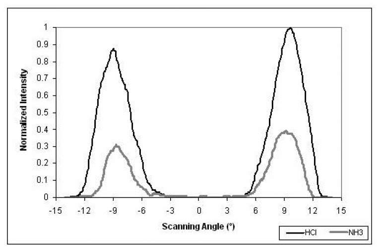
In previous sections, the results of the developed on-fiber sensors are presented using the total intensity modulation technique. In this section, an improvement in the sensor sensitivity, when the MPD method is applied, is recorded. This fiber sensing element was prepared by spinning polyaniline (3000 rpm) as the cladding material. A He-Ne laser with wavelength of 632.8 nm was used as the light source. The optical fiber was excited with an off-axis laser beam, and the far-field pattern was detected using a CCD camera. Figure 18 presents a sample of the far-field pattern before and after the sensor was exposed to HCl and NH3 vapors. The ring looked much brighter when the sensor was exposed to HCl vapor, Figure 18 (left). The whole ring became darker when the sensor was exposed to NH3 vapor, Figure 18 (right). The normalized radial intensity profiles of the ring patterns are shown in Figure 19. The change of the output reached 67% between exposed to HCl and NH3 chemical vapors. Compared with 26% change for the same sensor with total intensity method used before, it is shown that the MPD method can dramatically improve the sensor sensitivity.
Figure 18.
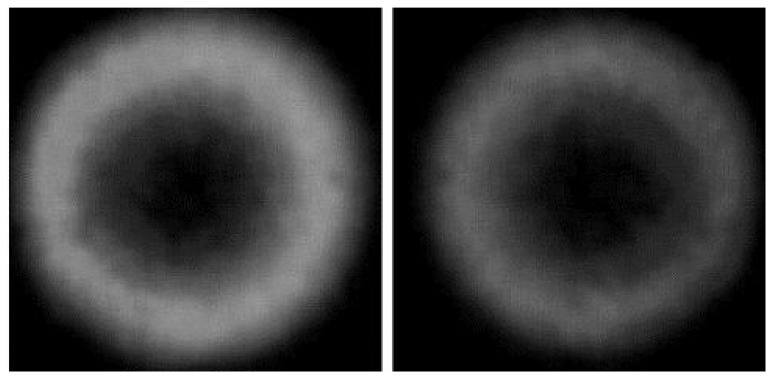
Far-field ring pattern of MPD: (left) after sensor exposure to HCl vapor and (right) after sensor exposure to NH3 vapor.
Figure 19.
Normalized intensity profiles of the 2-D ring pattern.
Conclusions
A novel class of on-fiber sensors was developed. It is based on using a chemical sensitive polymer as a modified cladding to multimode optical fibers. The sensing mechanisms are based on inducing changes in the light transmitted intensity in response to changes induced in the refractive index of the modified cladding material. Changing of the material refractive index is altered by environmental conditions, such as exposure chemical vapors. Conducting polymers, polyaniline and polypyrrole, were successfully tested for sensing toxic vapors, such as HCl, NH3, H2O2, H4N2, and DMMP. The measured sensitivities, in terms of the percentage optical intensity change, are; 51% for Ammonia, 91% for Hydrazin, 30% for HCl and 15.75% for DMMP. Room temperature vapor densities of the chemicals were used for detection which are: Ammonia: 0.59 (air = 1) , Hydrazin: 1.1 (air =1) , HCl: 1.257 (air =1), DMMP: 1.16 (air=1). In addition, the developed modal power distribution (MPD) technique was tested as a sensitive and inexpensive detection method, applicable for the sensor sensitivity improvement.
Acknowledgments
The authors would like to acknowledge the U.S. Army for its support and technical collaboration through the ARO-MURI project No. DAAH04-96-1-0018.
References and Notes
- 1.Wolfbeis O.S. Fiber optic chemical sensors and biosensors. Vol. 1&2 CRC Press; Boca Raton, Florida: 1991. 1992. [Google Scholar]
- 2.Stewart G., Jin W., Culshaw B. Prospects for fiber optic evanescent field gas sensors using absorption in the near infrared. Sensors & Actuators B. 1997;38:42–47. [Google Scholar]
- 3.Chan K., Ito H., Inable H. An optical fiber based gas sensor for remote adsorption measurement of low level methane gas in near infrared region. J. Lightwave Technology. 1984;2:234–237. [Google Scholar]
- 4.Wolfbeis O.S., Posch H. E. Fiber optic fluorescing sensor for ammonia. Anal. Chim. Acta. 1986;185:321–327. [Google Scholar]
- 5.Rowe-Taitt C.A., Ligler F. S. In: Fiber Optic Biosensors. Lopez-Higuera J.M., editor. John Wiley & Sons Ltd; 2001. pp. 687–700. Handbook of optical fiber sensing technology. [Google Scholar]
- 6.Ferguson J.A., Boyles T.C., Adams C.P., Walt D.R. Fiber optic DNA biosensor microarray for the analysis of gene expression. Nature Biotechnology. 1996;14:1681–1684. doi: 10.1038/nbt1296-1681. [DOI] [PubMed] [Google Scholar]
- 7.Healy B.G., Li L., Walt D. R. Multianalyte biosensors on optical imaging bundles. Biosensors & Bioelectronics. 1997;12:521–529. doi: 10.1016/s0956-5663(97)00009-2. [DOI] [PubMed] [Google Scholar]
- 8.Baker S.L.R., Kopelman R., Meyer T.E., Cusanovich M. A. Fiber optic nitric oxide selective biosensors and nanosensors. Analytical Chemistry. 1998;70:971–976. doi: 10.1021/ac970706k. [DOI] [PubMed] [Google Scholar]
- 9.Holst G., Mizaikoff B. In: Fiber Optic Sensors for Environmental Sensing. Handbook of optical fiber sensing technology. Lopez-Higuera J. M., editor. John Wiley & Sons Ltd; 2001. p. p 729. [Google Scholar]
- 10.Dietrich A. M. Measurement of pollutants: chemical species. Water Environmental Research. 1996;68:391–406. [Google Scholar]
- 11.Schwotzer G. Optical sensing of hydrocarbons in air or in water using UV absorption in the evanescent field of fibers. Sensors & Actuators B. 1997;38:150–153. [Google Scholar]
- 12.Mizaikoff B. Infrared fiber optic gas sensor for chlorofluorohydrocarbons. Vibrational Spectroscopy. 1995;8:103–108. [Google Scholar]
- 13.Anderson F. P., Miller W. G. Fiber optic immunochemical sensor for continuous, reversible measurement of phenytoin. Clinical Chemistry. 1988;34:1417–1427. [PubMed] [Google Scholar]
- 14.Riberio A. B. L., Jackson D. A. Low coherence fiber optic system for remote sensors illuminated by a 1.3 μm multimode laser diode. Review of Scientific Instruments. 1993;64:2974–2977. [Google Scholar]
- 15.El-Sherif M. A. Smart Textiles Created with Embedded Sensors. MRS Bulletin Technology Advances. 2003;28(2):101–102. [Google Scholar]
- 16.El-Sherif M. A., Yuan J., MacDiarmid A. Fiber Optic Sensors and Smart Fabrics. J. of Intelligent Materials Systems and Structures. 2000;2:407–414. [Google Scholar]
- 17.Yuan J., El-Sherif M. A. Fiber-Optic Chemical Sensor Using Polyaniline as modified Cladding Material. IEEE Sensor Journal. 2003;3(1):5–12. [Google Scholar]
- 18.Radhakrishnan J. PhD Thesis. 1996. Real time characterization of composite materials using fiber optics techniques. Advisor: Dr. Mahmoud A. El-Sherif. [Google Scholar]
- 19.Radhakrishnan J., El-Sherif M. A. Analysis on spatial intensity modulation for fiber optic sensor applications. J. Optical Fiber Technology. 1996;2(1):114–126. [Google Scholar]
- 20.Yuan J. PhD Thesis. 2001. Polymer materials as modified optical fiber cladding for chemical sensors. Advisor: Dr. Mahmoud A. El-Sherif. [Google Scholar]
- 21.MacDiarmid A. J. In: Sciences and technology of conducting polymers. Frontiers of polymer research. Presad P. N., Nikam J. K., editors. Plenum Press; New York: 1991. p. p259. [Google Scholar]
- 22.MacDiarmid A. G. Synthetic metals: a novel role for organic polymers. Synthetic Metals. 2001;125:11–22. doi: 10.1002/1521-3773(20010716)40:14<2581::AID-ANIE2581>3.0.CO;2-2. [DOI] [PubMed] [Google Scholar]
- 23.Collins G. E., Buckley L. J. Conductive Polymer-Coated Fabrics for Chemical Sensing. Synthetic Metals. 1996;78:93–101. [Google Scholar]
- 24.Potje-Kamloth K. Chemical gas sensors based on organic semiconductor polypyrrole. Critical reviews in analytical chemistry. 2002;32:121–140. [Google Scholar]
- 25.Bansal L., Khalil S., El-Sherif M. Fiber optic neurotoxin sensor.; Proceedings of the IEEE 28th Annual Northeast Philadelphia; 2002. pp. 20–21. [Google Scholar]
- 26.El-Sherif M. A. On-Fiber Sensor and Modulator. IEEE Transactions on Instrumentation and Measurement. 1989;38(2):595–598. [Google Scholar]
- 27.El-Sherif M. A. The Final Technical Report on Sensors and Smart Fabrics. 2001. The MURI-ARO (Army Research Office) project on Functionally Tailored Textiles, Contract #DAAH 01-96-1-0018. [Google Scholar]
- 28.El-Sherif M., Fidanboylu K., El-Sherif D., Gafsi R., Yuan J., Richards K., Lee C. A Novel Fiber Optic System for Measuring the Dynamic Structural Behavior of Parachutes. Journal of Intelligent Materials Systems and Structures. 2000;11:351–359. [Google Scholar]
- 29.El-Sherif M., Li M., El-Sherif D., Lee C. In: Fiber Optic System for Measuring the Structural Behavior of Parachute Airdrop: Quasi Static and Dynamic Testing. Chang F.K., editor. CRC Press; 2001. p. 733. Structure Health Monitoring. [Google Scholar]
- 30.Bansal L. PhD Thesis. Dec. 2004. Development of a fiber optic chemical sensor for detection of toxic vapor. Advisor: Dr. Mahmoud A. El-Sherif. [Google Scholar]
- 31.Yuan J., El-Sherif M. A., MacDiarmid A. G., Jones W. Fiber Optic Chemical Sensors Using Modified Conducting Polymer Cladding. Proc. Of SPIE. 2001;4205:170–179. [Google Scholar]
- 32.MacDiarmid A. G. Secondary doping in polyaniline. Synthetic Metals. 1995;69:85–92. [Google Scholar]
- 33.Liu J., Wan M. Polypyrrole doped with 1, 5-napthalenedisulphonic acid. Synthetic Metals. 2001;124:317–321. [Google Scholar]


