Abstract
Purpose
The goal of this study is to evaluate the accuracy of patient-specific CT-based rapid prototype drill templates for C2 translaminar screw insertion.
Methods
Volumetric CT scanning was performed in 32 cadaveric cervical spines. Using computer software, the authors constructed drill templates that fit onto the posterior surface of the C2 vertebrae with drill guides to match the slope of the patient’s lamina. Thirty-two physical templates were created from the computer models using a rapid prototyping machine. The drill templates were used to guide drilling of the lamina and post-operative CT images were obtained. The entry point and direction of the planned and inserted screws were measured and compared.
Results
Sixty-four C2 translaminar screws were placed without violating the cortical bone of a single lamina. The bilateral average transverse angle of intended and actual screw for C2TLS was 56.60 ± 2.22°, 56.38 ± 2.51°, 56.65 ± 2.24°, 56.39 ± 2.45°. The bilateral mean coronal angle of the planned and actual screw for C2TLS was 0°, 0°, −0.07 ± 0.32°, 0.12 ± 0.57°. The average displacement of the entry point of the superior and inferior C2TLS in the x, y, z axis was 0.27 ± 0.85, 0.49 ± 1.46, −0.28 ± 0.69, 0.43 ± 0.88, 0.38 ± 1.51, 0.23 ± 0.64 mm.
Conclusion
The small deviations seen are likely due to human error in the form of small variations in the surgical technique and use of software to design the prototype. This technology improves the safety profile of this fixation technique and should be further studied in clinical applications.
Keywords: Rapid prototyping, Post–pre registration, Personalized drill template, Computer-assisted, C2 translaminar screws
Introduction
Various fixation techniques have been described for upper cervical spine instability [1–3]. C1 lateral mass with C2 pedicle or pars screws (Goel et al. [5, 6] and Harms et al. [7]) and C1/C2 transarticular screws (Magerl et al. [8]) are popular options to obtain solid fusion of atlantoaxial vertebrae [4]. Unfortunately, variations in anatomy preclude safe placement of these screw constructs in up to 20 % of patients [10]. Another option is the C2 crossing-lamina screw, reported by Leonard and Wright [11–13]. This technique removes the risk of vertebral artery injury by screw perforation but demand accurate placement due to the relative location of the spinal cord just ventral to the screw tract. The C2TLS has been proven to be biomechanically stable [17] and has been successfully used in many clinical cases [14–16]. However, the study by Ma et al. [14] revealed a high rate of misplaced screws with 10 cortical breaches in their study of 68 translaminar screws. C2 translaminar screw insertion via rapid prototyping drill template (RPDT) has been introduced as a relatively simple and effective way to improve the accuracy of screw placement [18]. This article evaluates the accuracy of RPDT-C2TLS placement as well as possible reasons for the small deviations observed.
Materials and methods
Specimens
Thirty-two formalin-fixed cervical cadaver spines (C1–C7), including 17 male and 15 female, were obtained with permission from the Department of Anatomy at the University of Ningbo. The average age was 49.5 years, with a range of 25–65 years. Specimens were imaged with volumetric CT scanning (Philips Brilliance 64 CT, Philips Medical Systems, Netherland) with 0.625-mm slice thickness to exclude any deformity and images were stored in digital imaging and communications in medicine (DICOM) format. A refrigerator (SANYO, Japan) was used to keep the cervical specimens with preserved soft tissue at −20 °C. On the day before the experiment, the specimen was removed from the refrigerator and exposed to room temperature for thawing.
Construction of drill templates
The volumetric data stored in DICOM format were imported to the MIMICS 10.01 (Materialise, Belgium) to create a 3D reconstruction model of the cervical vertebrae. A 3.5 mm diameter cylinder was created rather than a screw with threads to allow direct visualization of any potential breach of the C2 laminar cortical bone in both the 2D and 3D reconstructions. Both the 3D cervical model and cylinders were transferred in stereo lithography (STL) format to a reverse engineer software [UG imageware 12.0 (EDS, US)]. This software allowed for final determination of optimal screw entry point, angulation, diameter and depth.
The RPDT is designed to closely approximate the posterior surface of the C2 lamina and spinous process in a lock-and-key type design. The substrate of the template that interfaces with the C2 bone has a thickness of 2.5 mm to ensure adequate strength for drilling. The drilling guides are directed towards the center of the bilateral lamina and are 15 mm in length with a hollow cylinder with an inner and outer diameter of 2.7 and 5.7 mm, respectively. The template was completed by perforating the drilling guide of the template through the Boolean operation (Fig. 1). The 3D models of template were then converted into a physical template which is produced in acrylate resin (Somos 14120, DSM Desotech Inc) using stereolithography—a rapid prototyping technique (Hen Tong company, China).
Fig. 1.

The 3D model of C2TLS drill template. The template on a vertebra (a), the dorsal aspect of the template (b), the ventral aspect of the template (c)
Insertion technique
After overnight thawing, the specimens were secured in a prone position for screw insertion. The spinous process, lamina and lateral mass of C2 were cleared of soft tissue to ensure an excellent fit of the template. The first lamina was drilled through the orienting tube of the template using a high speed 2.7 mm drill. The first drill was left in place to provide further stability during drilling of the second lamina. Each lamina was drilled to a safe depth as determined from the pre-operative imaging studies. The drills and template were then removed and 3.5 mm diameter screws of the appropriate length were placed in the previously drilled lamina (Fig. 2).
Fig. 2.
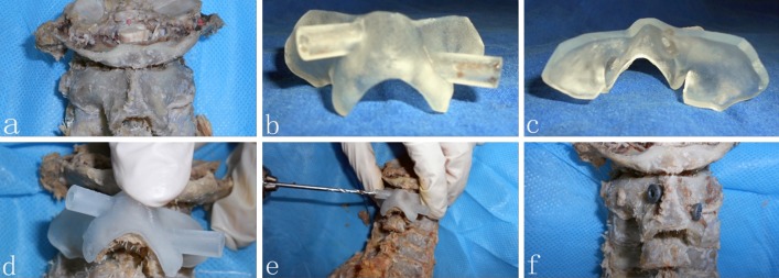
The application of the drill template. The posterior surface of atlantoaxial vertebrae with soft tissue removed (a), dorsal aspect of template (b), ventral aspect of template (c), the template on a vertebra (d), drill assisted by template (e), C2TLS fixed on C2 (f)
Assessment of drill template accuracy
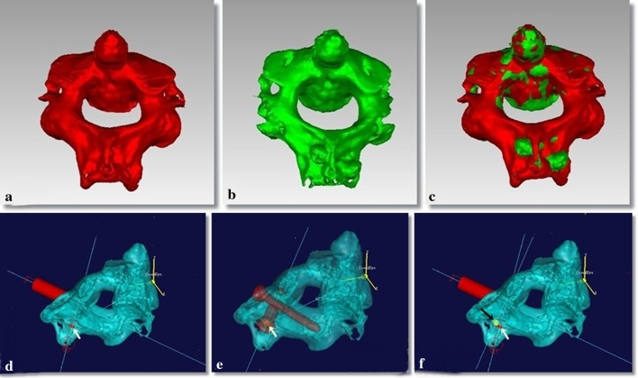
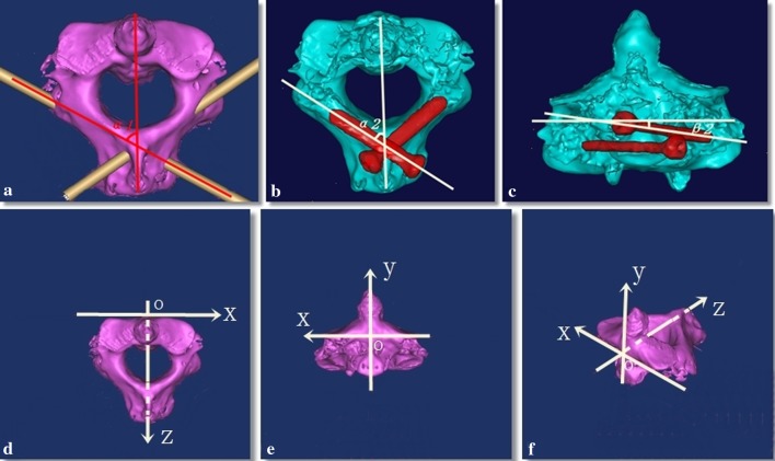
After drilling was completed using the RPDT, post-operative CT scans were obtained (Fig. 3). The volumetric data was stored in DICOM format and was imported to the MIMICS 10.01 (Materialise, Belgium) to calculate a 3D reconstruction of the cervical vertebrae and screw. Both the pre- and post-operative imaging of the cervical vertebrae were transferred in STL format to Geomagic Studio 9 (Geomagic, US). Four anatomic points were selected for both the pre- and post-operative imaging to ensure that the images were appropriately calibrated (Fig. 4a–c). The 3D model of C2 vertebrae allowed direct visualization of the screw and cylinder in the pre-operative space, and measurement of the transverse and coronal angle of cylinder and screw (Fig. 5a–c).
Fig. 3.

Post-operative CT images. Axial cuts in the plane of the translaminar screws (a, b), sagittal (c) and coronal (d) images
Fig. 4.
Geomagic studio images to evaluate the spatial position between pre- and post-operative images. The pre-operative image of C2 (a) and the post-operative image of C2 (b) are combined to reveal the spatial position between pre- and post-operative data (c). The entry point of the cylinder for C2TLS was marked by a red spot (d), the entry point of screw for C2TLS was marked by a yellow spot (e). The measurement of entry point data from planned to post-operative is shown (f)
Fig. 5.
Computer reconstructions revealing the measurement of the screw angles and the schematic diagram of the C2 space coordinates. The planned transverse angle of the cylinder for C2TLS (a). The planned transverse (b), and coronal (c) angles for placement of C2TLS. The defined C2 space coordinates (d–f)
To evaluate the 3D images appropriately, a coordinate axis was created. In the coronal plane, the line connecting the lowest point of the outer edge of the superior articulating process is the x-axis. The y-axis is defined as perpendicular to the x-axis with the intersection at the origin “o”. The z-axis passes through the “o” is perpendicular to both the x-axis and y-axis (Fig. 5d–f). This system allows measurement of the differences between the intended and the actual screw placement in the x, y, z axis (Δx, Δy, Δz) (Fig. 4d–f).
Data analysis
SPSS® 13.0 for windows (SPSS, Inc.) was used for statistical analysis with a paired t test to determine the statistical significance. Statistical significant was defined as P < 0.05.
Results
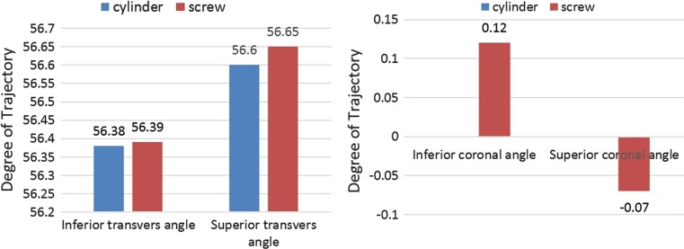
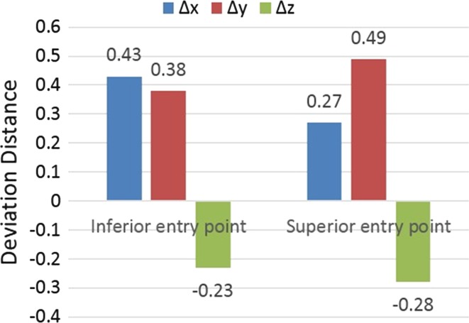
In total, 64 screws were placed using the RPDT without violation of a single laminar cortex. The average transverse angle of cylinder and screw for C2TLS is 56.60 ± 2.22°, 56.38 ± 2.51°, 56.65 ± 2.24°, 56.39 ± 2.45°. The bilateral mean coronal angle of the planned and screw for C2TLS is 0°, 0°, −0.07 ± 0.32°, 0.12 ± 0.57° (Table 1; Fig. 6). The average variation of the entry point of superior and inferior C2TLS in the x, y, z axis is 0.27 ± 0.85, 0.49 ± 1.46, −0.28 ± 0.69, 0.43 ± 0.88, 0.38 ± 1.51, −0.23 ± 0.64 mm (Table 2; Fig. 7). There was no statistically significant difference (P > 0.05) in the entry point or trajectory between the intended and actual translaminar screws.
Table 1.
Measurements of angle of pre- and post-operative C2TLS (mean ± SD, range)
| Measurements | STA (mean ± SD, range) |
ITA (mean ± SD, range) |
SCA (mean ± SD, range) |
ICA (mean ± SD, range) |
|---|---|---|---|---|
| Cylinder (°) | 56.60 ± 2.22, 53.69–61.44 | 56.38 ± 2.51, 51.99–61.02 | 0 | 0 |
| Screw (°) | 56.65 ± 2.24, 53.85–61.62 | 56.39 ± 2.45, 52.49–60.83 | −0.07 ± 0.32, −1.09 to 0.32 | 0.12 ± 0.57, −0.38 to 2.11 |
| P value | 0.228 | 0.942 | 0.407 | 0.39 |
C2TLS C2 translaminar screw, STA superior transverse angle, ITA inferior transverse angle, SCA superior coronal angle, ICA inferior coronal angle
Fig. 6.
Graph comparing the planned (cylinder) and actual (screw) angles of the translaminar screws revealing remarkable precision of screw placement
Table 2.
Measurements of entry points deviation between pre- and post-operative C2TLS (mean ± SD, range)
| Measurements | Δx (mean ± SD, range) | Δy (mean ± SD, range) | Δz (mean ± SD, range) |
|---|---|---|---|
| Superior (mm) | 0.27 ± 0.85, −1.02 to 1.51 | 0.49 ± 1.46, −1.89 to 2.41 | −0.28 ± 0.69, −1.21 to 1.52 |
| Inferior (mm) | 0.43 ± 0.88, −0.63 to 1.78 | 0.38 ± 1.51, −2.43 to 2.38 | −0.23 ± 0.64, −1.27 to 1.25 |
| P value, superior | 0.219 | 0.200 | 0.121 |
| P value, inferior | 0.069 | 0.331 | 0.172 |
C2TLS C2 translaminar screw
Fig. 7.
Graph illustrating the minimal deviation observed in the entry points of the translaminar screws in all three planes
Discussion
It has been accepted that C2 translaminar screw fixation can be used as an alternative technique for the treatment of atlantoaxial instability caused by trauma, tumor, rheumatic disease or other degenerative process [19]. However, there is a risk of ventral lamina cortex breech and subsequent spinal cord injury when these screws are placed with a free-hand technique [20]. The screws should be placed as dorsal as possible [21, 22] but the C2 spinous process may limit the transverse angle of the screw trajectory [23]. It is difficult to visualize the relationship of a C2TLS and the spinal canal with 2D fluoroscopy and thus 3D image-guidance technology may have a role in screw placement [24–26]. This technology offers several advantages such as real-time feedback of the screw trajectory in all three planes and determination of appropriate lengths and diameters for screws. Because of the limitations in this technology, including both practical application and accuracy in the clinical setting, other options to guide screw placement must be studied. RPDT technology may allow precise and individualized drilling and screw placement in the cervical spine while reducing the risk of spinal cord injury.
Authors have designed different individual templates for C2 level screw placement, including pedicle, translaminar and Magerl screw placement [18, 27–30]. The keys to successful template design include precise fit, stability during drilling and practicality in the clinical setting. Lu et al. [18] and Kawaguchi et al. [28] have designed templates for C2 screw placement. However, our bilateral design has significantly more surface area to allow greater stability during drilling. Further, using two drill bits during the procedure, drilling of the second screw path is performed with the template rigidly secured to the bone.
The objective of this study was to evaluate the accuracy of C2TLS placement using our RPDT. The entry point and screw channel were evaluated to ensure that screws were placed completely within laminar bone. The screw tract was approximated using 3.5 mm cylinders to allow direct visualization in both the 2D and 3D models of any cortical perforation of the screw tract.
Accurate screw placement using template technology requires careful template construction and application. The process from image transfer to final template production required 2–3 days. The ventral surface of the template must closely match the dorsal surface of the lamina to allow precise drilling and screw placement. To ensure an excellent fit, fine cut CT scan is necessary. To facilitate accurate template production, the operator who creates the 3D model must understand cervical anatomy to ensure that the model is reasonable given the fact that the format conversion between STL and DICOM can result in data loss. During the procedure, care must be taken to remove all soft tissues from the posterior spinal elements to ensure excellent fit between the template and the bone. The assistant must help stabilize the template by resisting any posterior or superior forces and the surgeon must carefully follow the direction of the drill guide and proceed in short (1 mm) increments to ensure that the drill remains in the lamina. This technique requires meticulous preparation and denudation of the lamina and spinous of C2 to ensure stability of the template. It is worth noting that this is not possible with minimally invasive techniques as a traditional exposure is required to remove the soft tissue and allow proper template placement. This may cause additional soft tissue trauma, but this is likely much less morbid than a misplaced C2 translaminar screw.
Conclusion
Translaminar screw placement using a RPDT is technically feasible and results in accurate and precise screw placement. This patient-specific technology can likely improve the safety profile of this fixation method and should be further studied in clinical applications.
Conflict of interest
None.
References
- 1.Bransford RJ, Russo AJ, Freeborn M, et al. Posterior C2 instrumentation: accuracy and complications associated with four techniques. Spine. 2011;36:E936–E943. doi: 10.1097/BRS.0b013e3181fdaf06. [DOI] [PubMed] [Google Scholar]
- 2.Guo Q, Liu J, Ni B, et al. C2 laminar screw and C1–2 transarticular screw combined with C1 laminar hooks for atlantoaxial instability with unilateral vertebral artery injury. Arch Orthop Trauma Surg. 2011;131:1207–1210. doi: 10.1007/s00402-011-1277-6. [DOI] [PubMed] [Google Scholar]
- 3.Hong JT, Yi JS, Kim JT, et al. Clinical and radiologic outcome of laminar screw at C2 and C7 for posterior instrumentation—review of 25 cases and comparison of C2 and C7 intralaminar screw fixation. World Neurosurg. 2010;73:112–118. doi: 10.1016/j.surneu.2009.06.010. [DOI] [PubMed] [Google Scholar]
- 4.Lee SH, Kim ES, Sung JK, et al. Clinical and radiological comparison of treatment of atlantoaxial instability by posterior C1–C2 transarticular screw fixation or C1 lateral mass-C2 pedicle screw fixation. J Clin Neurosci. 2010;17:886–892. doi: 10.1016/j.jocn.2009.10.008. [DOI] [PubMed] [Google Scholar]
- 5.Goel A, Laheri V. Plate and screw fixation for atlanto-axial subluxation. Acta Neurochir. 1994;129:47–53. doi: 10.1007/BF01400872. [DOI] [PubMed] [Google Scholar]
- 6.Goel A, Desai KI, Muzumdar DP. Atlantoaxial fixation using plate and screw method: a report of 160 treated patients. Neurosurgery. 2002;51:1351–1356. [PubMed] [Google Scholar]
- 7.Harms J, Melcher RP. Posterior C1–C2 fusion with polyaxial screw and rod fixation. Spine. 2001;26:2467–2471. doi: 10.1097/00007632-200111150-00014. [DOI] [PubMed] [Google Scholar]
- 8.Jeanneret B, Magerl F. Primary posterior fusion C1/2 in odontoid fractures: indications, technique, and results of transarticular screw fixation. J Spinal Disord. 1992;5:464–475. doi: 10.1097/00002517-199212000-00012. [DOI] [PubMed] [Google Scholar]
- 9.Guo X, Ni B, Zhao W, et al. Biomechanical assessment of bilateral C1 laminar hook and C1–2 transarticular screws and bone graft for atlantoaxial instability. J Spinal Disord Tech. 2009;22:578–585. doi: 10.1097/BSD.0b013e31818da3fe. [DOI] [PubMed] [Google Scholar]
- 10.Xu H, Chi YL, Wang XY, et al. Comparison of the anatomic risk for vertebral artery injury associated with percutaneous atlantoaxial anterior and posterior transarticular screws. Spine J. 2012;12:656–662. doi: 10.1016/j.spinee.2012.05.010. [DOI] [PubMed] [Google Scholar]
- 11.Wright NM. Posterior C2 fixation using bilateral, crossing C2 laminar screws: case series and technical note. J Spinal Disord Tech. 2004;17:158–162. doi: 10.1097/00024720-200404000-00014. [DOI] [PubMed] [Google Scholar]
- 12.Leonard JR, Wright NM. Pediatric atlantoaxial fixation with bilateral, crossing C-2 translaminar screws. J Neurosurg. 2006;104:59–63. doi: 10.3171/ped.2006.104.1.59. [DOI] [PubMed] [Google Scholar]
- 13.Wright NM. Translaminar rigid screw fixation of the axis. J Neurosurg Spine. 2005;3:409–414. doi: 10.3171/spi.2005.3.5.0409. [DOI] [PubMed] [Google Scholar]
- 14.Ma W, Feng L, Xu R, et al. Clinical application of C2 laminar screw technique. Eur Spine J. 2010;19:1312–1317. doi: 10.1007/s00586-010-1447-1. [DOI] [PMC free article] [PubMed] [Google Scholar]
- 15.Nakanishi K, Tanaka M, Sugimoto Y, et al. Application of laminar screws to posterior fusion of cervical spine: measurement of the cervical vertebral arch diameter with a navigation system. Spine. 2008;33:620–623. doi: 10.1097/BRS.0b013e318166aa76. [DOI] [PubMed] [Google Scholar]
- 16.Hu Y, Gu YJ, Ye PH, et al. Posterior cervical spine arthrodesis incorporating C2 laminar screw fixation in the treatment of cervical spine injury. Orthop Surg. 2010;2:32–37. doi: 10.1111/j.1757-7861.2009.00062.x. [DOI] [PMC free article] [PubMed] [Google Scholar]
- 17.Lapsiwala SB, Anderson PA, Oza A, et al. Biomechanical comparison of four C1 to C2 rigid fixative techniques: anterior transarticular, posterior transarticular, C1 to C2 pedicle, and C1 to C2 intralaminar screws. Neurosurgery. 2006;58:516–521. doi: 10.1227/01.NEU.0000197222.05299.31. [DOI] [PubMed] [Google Scholar]
- 18.Lu S, Xu YQ, Zhang YZ, et al. A novel computer-assisted drill guide template for placement of C2 laminar screws. Eur Spine J. 2009;18:1379–1385. doi: 10.1007/s00586-009-1051-4. [DOI] [PMC free article] [PubMed] [Google Scholar]
- 19.Wang S, Wang C, Passias PG, et al. Pedicle versus laminar screws: what provides more suitable C2 fixation in congenital C2–3 fusion patients? Eur Spine J. 2010;19:1306–1311. doi: 10.1007/s00586-010-1418-6. [DOI] [PMC free article] [PubMed] [Google Scholar]
- 20.Park JS, Cho DC, Sung JK. Feasibility of C2 Translaminar Screw as an alternative or salvage of C2 pedicle screws in atlantoaxial instability. J Spinal Disord Tech. 2012;25:254–258. doi: 10.1097/BSD.0b013e318218a4f7. [DOI] [PubMed] [Google Scholar]
- 21.Wang MY. Cervical crossing laminar screws: early clinical results and complications. Neurosurgery. 2007;61:311–315. doi: 10.1227/01.neu.0000303987.49870.7b. [DOI] [PubMed] [Google Scholar]
- 22.Wang MY. C2 crossing laminar screws: cadaveric morphometric analysis. Neurosurgery. 2006;59:ONS84–ONS88. doi: 10.1227/01.NEU.0000219900.24467.32. [DOI] [PubMed] [Google Scholar]
- 23.Kabir SMR, Casey AT. Modification of Wright’s technique for C2 translaminar screw fixation: technical note. Acta Neurochir. 2009;151:1543–1547. doi: 10.1007/s00701-009-0459-2. [DOI] [PubMed] [Google Scholar]
- 24.Rajasekaran S, Avadhani A, Shetty AP. Axial translaminar screw placement using three-dimensional fluoroscopy-based navigation. Singap Med J. 2011;52:15–18. [PubMed] [Google Scholar]
- 25.Nottmeier EW, Foy AB. Placement of C2 laminar screws using three-dimensional fluoroscopy-based image guidance. Eur Spine J. 2008;17:610–615. doi: 10.1007/s00586-007-0557-x. [DOI] [PMC free article] [PubMed] [Google Scholar]
- 26.Lehman RA, Jr, Sasso RC, Helgeson MD, et al. Accuracy of intraoperative plain radiographs to detect violations of intralaminar screws placed into the C2 vertebrae: a reliability study. Spine. 2007;32:3036–3040. doi: 10.1097/BRS.0b013e31815cdab9. [DOI] [PubMed] [Google Scholar]
- 27.Lu S, Xu YQ, Chen GP, et al. Efficacy and accuracy of a novel rapid prototyping drill template for cervical pedicle screw placement. Comput Aided Surg. 2011;16:240–248. doi: 10.3109/10929088.2011.605173. [DOI] [PubMed] [Google Scholar]
- 28.Kawaguchi Y, Nakano M, Yasuda T, et al. Development of a new technique for pedicle screw and magerl screw insertion using a 3-dimensional image guide. Spine. 2012;37:1983–1988. doi: 10.1097/BRS.0b013e31825ab547. [DOI] [PubMed] [Google Scholar]
- 29.Goffin J, Van Brussel K, Martens K, et al. Three-dimensional computed tomography-based, personalized drill guide for posterior cervical stabilization at C1–C2. Spine. 2001;26:1343–1347. doi: 10.1097/00007632-200106150-00017. [DOI] [PubMed] [Google Scholar]
- 30.Van Cleynenbreugel J, Schutyser F, Goffin J, et al. Image-based planning and validation of C1–C2 transarticular screw fixation using personalized drill guides. Comput Aided Surg. 2002;7:41–48. doi: 10.3109/10929080209146015. [DOI] [PubMed] [Google Scholar]


