Abstract
In vitro recapitulation of mammalian embryogenesis and examination of the emerging behaviours of embryonic structures require both the means to engineer complexity and accurately assess phenotypes of multicellular aggregates. Current approaches to study multicellular populations in 3D configurations are limited by the inability to create complex (i.e. spatially heterogeneous) environments in a reproducible manner with high fidelity thus impeding the ability to engineer microenvironments and combinations of cells with similar complexity to that found during morphogenic processes such as development, remodelling and wound healing. Here, we develop a multicellular embryoid body (EB) fusion technique as a higher-throughput in vitro tool, compared to a manual assembly, to generate developmentally relevant embryonic patterns. We describe the physical principles of the EB fusion microfluidic device design; we demonstrate that >60 conjoined EBs can be generated overnight and emulate a development process analogous to mouse gastrulation during early embryogenesis. Using temporal delivery of bone morphogenic protein 4 (BMP4) to embryoid bodies, we recapitulate embryonic day 6.5 (E6.5) during mouse embryo development with induced mesoderm differentiation in murine embryonic stem cells leading to expression of Brachyury-T-green fluorescent protein (T-GFP), an indicator of primitive streak development and mesoderm differentiation during gastrulation. The proposed microfluidic approach could be used to manipulate hundreds or more of individual embryonic cell aggregates in a rapid fashion, thereby allowing controlled differentiation patterns in fused multicellular assemblies to generate complex yet spatially controlled microenvironments.
Introduction
The highly organized sequence of events comprising embryonic morphogenesis has been primarily studied in amphibians and birds, and thus many questions regarding tissue patterning in mammalian embryonic development remain unclear. Existing in vivo models are often difficult to manipulate to probe complex developmental processes, and are limited to peripheral tissue examination by the opacity of embryos1. Pluripotent embryonic stem cells (ESCs) are a promising source of progenitors and functionally differentiated cell types with significant implications in understanding the fundamentals of mammalian embryogenesis and developmental biology2, 3. However, monolayer cultures of ESCs or 3D multi-cellular aggregates derived from ESCs, called embryoid bodies (EB), are limited by the inability to create complex (i.e. spatially heterogeneous) environments in a reproducible manner with high fidelity and accurately characterize individual aggregates4–7. EB-mediated differentiation of cells, analogous to that of embryos8, is controlled by intercellular adhesions and extracellular gradients of morphogenic cues and chemical signals9. Recent studies have demonstrated the ability to direct the differentiation of ESCs by exogenous administration of molecules known to be involved in cell fate determination3, 9, 10. Nevertheless, robust and reliable spatial organization of the 3D environment in EBs is typically difficult to achieve6, 11. In order to generate fused multicellular 3D-aggregates in a repeatable manner, there is a significant need for a high-content engineering tool that simultaneously allows for direct visualization and phenotype analysis of individual multicellular aggregates. Such tools can facilitate greater understanding of complex developmental processes, such as the initiation of gastrulation through mesoderm differentiation of pluripotent cells.
We have previously developed a microfluidic embryo-trap array that automatically orients hundreds of fruit fly embryos for quantitative studies of embryogenesis8, 12. We modified this microfluidic approach for mammalian embryoid bodies to sequentially trap, pattern, and manipulate them in a rapid, well-controlled fashion thereby controlling the formation of multicellular aggregates to generate more complex geometric configurations (i.e. clusters of cells of different types, microenvironments and/or ratios of cells). Here we have developed a microfluidic array to sequentially trap two EBs with programmed microenvironments in a controlled manner for complex 3D spatial assemblies. We trapped and fused two different types of EBs formed from same initial ESC population, but exposed to different morphogenic cues. To demonstrate the power of EB fusion as an in vitro model of early embryonic development, we addressed an important question in developmental biology. To date, most embryonic pattern development studies require isolation of mammalian embryos. Previous studies have shown that short-term treatment with BMP4 induces mesoderm differentiation in mouse ESCs13, 14 and human ESCs15. Using our microfluidic device, we investigated the possibility of inducing a primitive streak-like pattern formation (mesoderm differentiation) by fusing EBs with locally engineered BMP4 microenvironments. The EB trapping arrays enable rapid parallel-processing and manipulation of complex multi-cellular aggregates, and controlled formation with subsequent manipulation and sorting. The ability to generate spatially patterned in vitro early developmental models in a configurable, reproducible, and higher-throughput manner will have a significant impact on embryogenesis research and understanding developmental disorders16.
Experimental Methods
Device fabrication
Microfluidic devices were fabricated from poly(dimethyl siloxane) (PDMS, Sylgard 184, Dow Corning) using multilayer soft-lithography techniques17. The device was composed of two PDMS layers which were designed in AutoCAD 2010 (Autodesk) and masks were printed on transparent sheets by CAD Services (California). Masters were fabricated on silicon wafers using SU82050 and SU8-2100 (MicroChem), and treated with tridecafluoro-(1,1,2,2-tetrahydrooctyl)-1-trichlorosilane silane (UCT Specialties, LLC). Each of the two layers was then molded into PDMS with base polymer to cross-linker ratio of 20:1 (valve layer) and 5:1 (flow layer). The 170 µm thick flow layer was partially cured at 70 °C for 20 min at a PDMS thickness of 3 mm. Next, the valve layer master was spin-coated to a thickness of 70 µm and partially cured on a hot-plate at 65 °C for 10 min, giving a 20 µm membrane between the flow channels and the valve layer. Finally, the two layers were aligned under a microscope and thermally bonded at 70 °C for 2 h. Individual devices were cut, access holes were punched and devices were bonded on cover slips after brief exposure to oxygen plasma (PDC-32G plasma cleaner, Harrick Plasma, Ithaca, NY).
Embryonic stem cell culture and maintenance
Murine ESCs (D3 cell line) were expanded on tissue culture treated polystyrene dishes (Corning Inc., Corning, NY) adsorbed with 0.1% gelatin (Mediatech, Manassas, VA)9. Undifferentiated ESC media consisted of Dulbecco's Modified Eagle's Medium (DMEM; Mediatech) containing 15% fetal bovine serum (Hyclone, Logan, UT), 100 U/ml penicillin (Mediatech), 100 µg/ml streptomycin (Mediatech), 0.25 µg/ml amphotericin (Mediatech), 2 mM L-glutamine (Mediatech), 1× MEM non-essential amino acid solution (Mediatech), 0.1 mM 2-mercaptoethanol (Fisher Scientific, Fairlawn, NJ), and 103 U/ml leukemia inhibitory factor (LIF; ESGRO, Millipore, Billerica, MA). Culture media was exchanged every other day, and cells were passaged at approximately 70% confluence.
The Brachyury-T-green fluorescent protein (T-GFP) mouse embryonic stem cell line (derived from 129/Ola cell line with GFP cDNA targeted to the T locus) was cultured in an undifferentiated state on 0.5% gelatin coated plates in LIF-containing media as described previously18. T-GFP mESCs were treated with 0.05% trypsin to obtain a single cell suspension, and forced to aggregate within AggreWell 400 inserts (Stem Cell Technologies, Vancouver, CA) as previously reported9, 19, 20. The defined culture media was composed of a DMEM/F12 (50/50) (Thermo Scientific) media supplemented with N2 (Gibco) and 50 mg/ml BSA (Millipore) in a 1:1 combination with B27 (Gibco) supplemented Neurobasal™medium (Gibco) with 100 U/ml penicillin, 100 µg/ml streptomycin, and 0.25 µg/ml amphotericin and 2mM L-glutamine18, 21. Briefly, 2.4×10^5 cells in 0.5 ml media were inoculated into the AggreWell inserts and centrifuged at 200g for 5 min, distributing ~200 cells per microwell. The resulting EBs were characterized for expression of T-GFP under the effect of soluble BMP4, using flow cytometry. T-GFP expression increased from day 2 (0.4 %) to day 5, with the maximum expression at day 5 (41%) followed by a decrease in the % of GFP+ cells on day 6 (22%) and day 8 (11%). For BMP4 delivery studies, gelatin microparticles (MP) laden with 125 ng BMP4 per mg MPs were prepared as reported previously9. For MP incorporation conditions, MPs were homogenously mixed with the cells before the mixture was added to AggreWell inserts9. After 24 hours of culture, a wide-bore pipette was used to gently remove cell aggregates from the AggreWell inserts and transferred to a rotary orbital shaker (40 rpm) for suspension culture to maintain the homogeneity of the population thereafter9.
Device operation and dye visualization experiments
Devices were rinsed with 70% ethanol followed by 500 µl PBS. To prevent non-specific binding, the device was filled with heat-denatured BSA (1% w/v in PBS) for 30 min. The device was finally flushed with 100 µl cell media. The valve layer was filled with water to prevent bubbles in the main channel. To prevent the larger EBs or EB aggregates from blocking the device, the EB suspension was filtered through a 150 µm mesh (Small Parts) and the filtered EBs were suspended in culture media with Percoll (GE Healthcare Life Science; final media density of 1.05 gm/ml) to prevent the EBs from settling immediately due to gravity. An embryoid body filter (50×50×170 µm; length × width × height) was also included at the inlet to prevent the entry of EBs >140 µm in diameter into the main serpentine flow channel. The filtered EB suspension was loaded into a pipette attached to the inlet and EBs were loaded by aspirating media from the outlet port. A 200 µl pipette filled with media remained attached to one of the inlets to serve as a media reservoir. The end of the pipette was sealed with sterile foil to prevent anything from entering into the device. The EB-loaded devices were carefully transferred to the incubator and left undisturbed overnight.
To illustrate the flow patterns in the device, food dyes (McCormick & Company, Inc., Sparks) were mixed with deionized water as a carrier fluid and filter sterilized using a 0.02 µm syringe filter to eliminate any aggregated material. A combination of different color dyes (red, blue, green) were flowed into the devices at an average velocity of 1 mm/sec through the main serpentine channel. All fluids reached steady-state within 30 sec and images were acquired using a stereo microscope.
Results and Discussion
Device design rationale and dye visualization
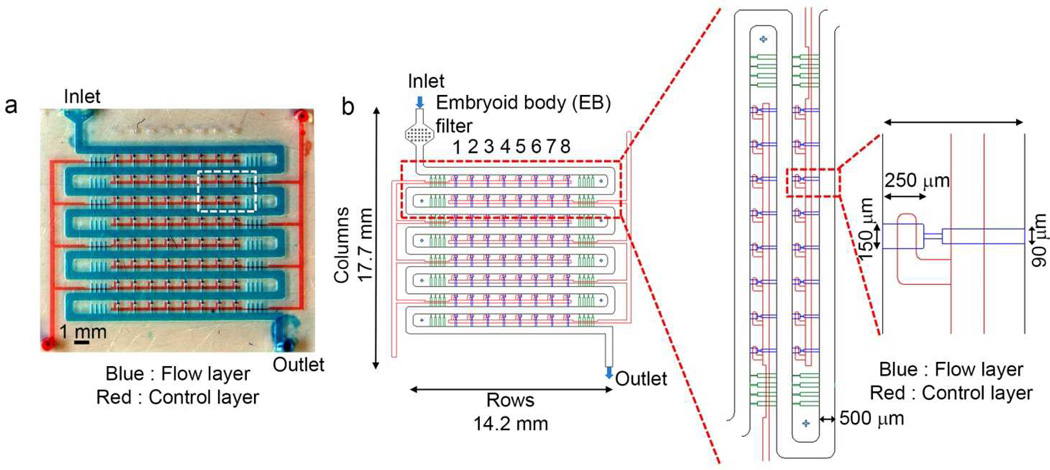
We designed a two layered sandwich device, fabricated from polydimethylsiloxane (PDMS), to sequentially trap EBs in an arrayed fashion (Fig 1a). The device consisted of an array of 64 traps configured within a 14 mm × 14 mm device (Fig. 1b). The overall design and device dimensions are indicated in Fig 1b. Unlike previously published hydrodynamic-based cell trapping approaches that require properly balanced flow resistance22, 23, our design simply relied on physical exclusion where the width of a single trap can only accommodate a single EB at a time.
Figure 1.
Microfluidic embryoid body-trap arrays for higher-throughput fusion of multiple EBs. (a) Photograph of the device with blue dye flowing through the top flow layer where EBs enter and get trapped and red dye represents bottom valve layer. (b) Details of the EB-trap array design (top view).
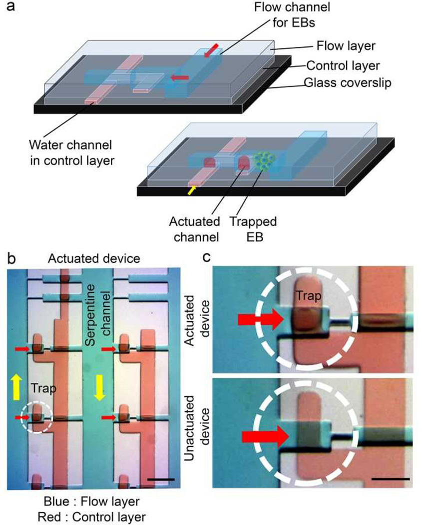
The design consists of a serpentine fluid-delivery manifold and an array of cross-flow channels (Fig. 1b). The 500-µm-wide serpentine channel is wider than the near spherical embryoid bodies used in our studies (~120 µm), allowing unobstructed flow of EBs in channels without any blockage. The primary rationale behind the use of a two-layer device was to minimize entrapment of the same type of EBs in a single fusion channel. The valve layer upon actuation creates a sieve structure in the channel layer through which the EBs flow. When an EB approached an empty trap, flow through the trap guided it into the trap. In order to sequentially trap two different types of EBs in a single fusion trap, the valves were pressurized to deflect the membrane into the flow layer covering the bottom half of a fusion channel (Fig 2a). Because of the rectangular cross section of the flow channel, the pressurized valves permitted the fluid to flow while still preventing the EBs from dropping into the lower half of the trap. Consequently, the first population of EB was trapped only in the top half of an empty trap (Fig 2b, c).
Figure 2.
Embryoid body trapping process and device cross-section (a) When an EB approaches an empty trap, flow through the device guides it into the trap. In order to sequentially trap two different types of EBs in a single fusion trap, the valves are pressurized which deflects the membrane into the flow layer covering the bottom half of a fusion channel. Because of the rectangular cross section of the flow channel, these pressurized valves let the fluid go through while still preventing the EBs from falling into the lower half of trap. (b) A section of the array showing actuated and unactuated states of device. Yellow arrows show the direction of bulk flow in the serpentine channel. Scale bar, 500 µm. (c) An actuated state (red dye) represents blocking of the lower half of a fusion trap while an unactuated state has diminished color. Scale bar, 250 µm.
Trapping of single embryoid bodies in fusion traps
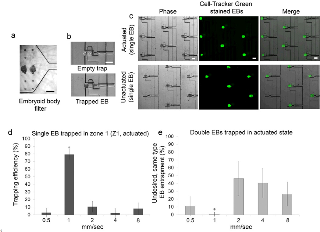
We created EBs of nearly 120 µm diameter from mouse ESCs using an AggreWell technique and introduced into the device with fusion traps that were 150 µm wide and 250 µm deep. The EBs were filtered through a 150 µm sieve (Fig 3a) and transported into the fusion traps via the cross-flow. Population 1 EBs (green) flowing in the serpentine channels were trapped sequentially in the upper half of the traps in the actuated state, referred to as zone Z1 (Fig. 3b, c). Thereafter, the valves were unactuated resulting in population 1 EBs being pushed down into the inner half of the traps (zone Z2) due to flow (Fig. 3c). We next evaluated the effect of average fluid flow velocity on the entrapment efficiency of EBs. When introduced at 1 mm/sec, maximum EB entrapment was achieved (80 ± 6 %, p < 0.05, Fig 3d). At a higher velocity of 2 mm/sec, EBs accumulated near the traps and clumped together, resulting in a marked decrease in trapping efficiency (10 ± 7 %). When the velocity was further increased to 4 and 8 mm/sec, the EBs often squeezed through the trap and crossed-over into the next serpentine flow channel. In contrast, at lower velocity (0.5 mm/sec), the EBs moved very slowly resulting in agglomeration and poor trapping efficiency (Fig 3d). The velocities examined here are reported only for ~120 µm diameter EBs and further optimal design of an array and flow velocities to accommodate larger sized EBs would be required and could easily be designed as necessary. An important criterion for sequential trapping and embryonic patterning was that only one population of EBs was trapped in a channel at a time, i.e. population 1 EB in first flow and population 2 EB in second flow positioning itself on top of population 1 EB. We examined the effect of fluid velocity on undesirable trapping of multiple EBs from population 1 in the same trap (referred to as “false trapping” here). At higher velocities of 2, 4, and 8 mm/sec, we observed a high probability of undesirable false trapping with 46 ± 21 %, 40 ± 19 %, and 26 ± 15 %, respectively (Fig 3e). In contrast, we observed minimal false trapping at 1 mm/sec with less than 1 % double EBs occupying the traps. These results strongly correlate to the single EB trapping efficiency in Fig 3d, and therefore 1 mm/sec fluid velocity was used for all of these studies.
Figure 3.
Entrapment of single EBs. (a) An embryoid body filter prevents entry of EBs >140 µm in diameter into the main serpentine flow channel. (b) When an EB approaches an empty trap with zones Z1 and Z2, flow through the trap guides it into the Z1. The valves remain pressurized which deflects the membrane into the flow layer preventing EBs from entering into Z2. (c) A section of the array showing fluorescently stained EBs trapped in Z1. (d) Trapping efficiency of a single EB type with respect to the average velocity in the main serpentine channel. Values represent mean ± s.d of number of EBs that are only trapped in Z1. (e) Undesired double occupancy of the same EB type in both zones (Z1 and Z2) with respect to the flow velocity in the serpentine channel. Values represent mean ± s.d of percentages of double occupancy during the initial flow (i.e. without introducing another batch of EBs).*P < 0.05, n = 3, pairwise comparison (t-test). Scale bar, 200 µm.
Multicellular aggregate patterning in fusion traps
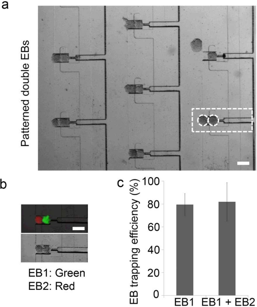
We next assessed the feasibility of trapping EBs from population 2 with EBs from population 1 for embryonic patterning. Embryonic stem cells express high levels of E-Cadherin24, 25 and frequently merge in an uncontrolled manner in static suspension cultures. Thus, we anticipated that when two EBs were sequentially trapped next to each other, they would merge to form the patterning of distinct embryonic stem cell aggregates. To demonstrate the ability to sequentially trap technique, EBs stained with green cell tracker dye (population 1) were entrapped first and thereafter red EBs (population 2) were introduced into the flow channel. As indicated in Fig 4a, b, we obtained a substantial entrapment of both population 1 and 2 EBs within the same trap. Importantly, more than 80% of the traps were occupied in the first round of flow with population 1 EB (Fig 4c) and 82 ± 16 % occupancy of both population 1 and 2 EBs.
Figure 4.
Entrapment of two distinct EBs for embryonic patterning. (a) A section of the array showing EBs trapped in Z1 and Z2 in a higher-throughput, reproducible manner. (b) Embryonic patterning in fusion traps. Green EBs (population 1) were entrapped first and thereafter red EBs (population 2) were flowed into the flow channel. (c) Trapping efficiency of a single EB (EB1 in Z1) and distinct EBs (EB1 in Z1 + EB2 in Z2). Values represent mean ± s.d, n = 3. Scale bar, 200 µm.
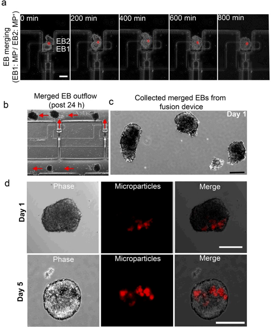
We next evaluated the ability to fuse microparticle encapsulated EBs with EBs lacking microparticles and monitored the spatial localization of entrapped microparticles. Using live cell imaging we observed that the two types of EBs started merging together within ~200 min from the point of introduction of a secondary EB (Fig 5a). The two EBs fused together to form a single conjoined structure over 600–800 min and interestingly, throughout the merging process, the encapsulated microparticles remained localized in the original EB hemisphere in which they were entrapped (Fig 5a), which correlates well to our previous reports on manual assembly of stem cell aggregates using paramagnetic microparticles and magnetic forces11.
Figure 5.
EB fusion, harvest, and culture of patterned structures. (a) Time lapse phase images demonstrating fusion of two EBs. Top EB has embedded microparticles that retain their spatial localization during the fusion process. Scale bar, 100 µm. (b) A section of the array showing ejection of fused EBs outside the fusion traps with reverse flow. Ejected EBs are (c) collected in culture wells, and (d) grow in size over the next 5 days while the microparticles remain localized to only one hemisphere. Scale bar, 200 µm.
After establishing the sequential patterning and merging of EBs, we evaluated the efficacy of harvesting conjoined multi-EB structures using a reverse hydrodynamic flow (flow velocity 2 mm/sec) to eject EBs from the traps. As indicated in Fig 5b, merged EBs were ejected out of the EB traps into the flow channels with > 95% recovery and collected into petri dishes (Fig 5c) for further culture. The harvested merged EBs were cultured thereafter in rotary orbital suspension culture 10, 11, 26, 27, during which time EBs increased in size and retained the MPs localized within the original EB over 5 days of suspension culture (Fig 5a,d). The microfluidic embryonic patterning method employed here does not require manual manipulation to merge ESC aggregates, is a highly sequential process, and allows for parallel higher-throughput fusion of multicellular structures for fundamental embryonic development studies.
Embryonic patterning with selective induction of mesoderm differentiation
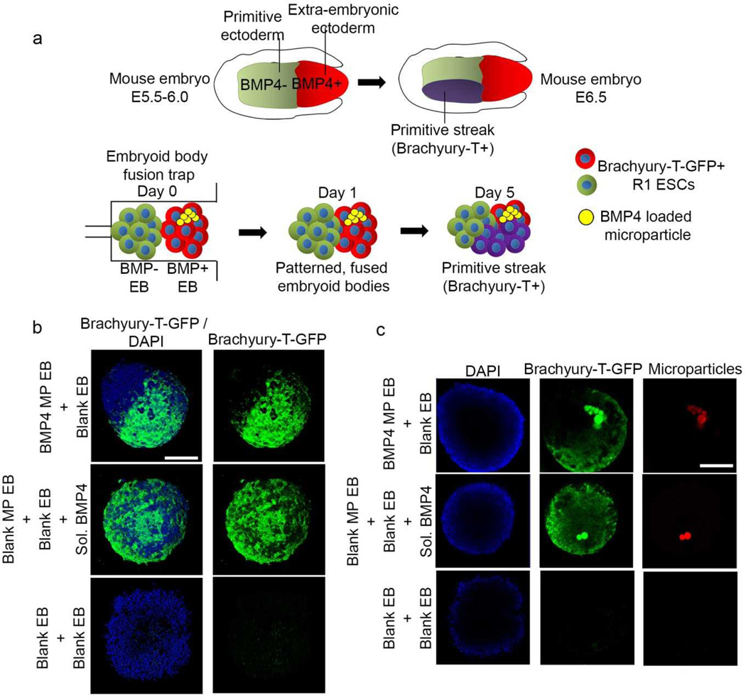
Earlier studies of mouse embryos have demonstrated that cells rely on positional cues obtained from interactions with neighbouring cells and local availability of morphogens to determine their lineage patterning during embryonic development28–33. A potent morphogen is the transforming growth factor-beta (TGF-β) superfamily member, bone morphogenetic protein 4 (BMP4) that directs embryonic patterning in mouse embryos28–33. On embryonic day 5.5 (E5.5), BMP gradients from extra-embryonic ectoderm promote mesoderm differentiation (Fig 6a). BMP4-mediated signalling results in initiation of the primitive streak that marks the beginning of gastrulation at E6.534–37.
Figure 6.
Embryonic patterning with selective induction of mesoderm differentiation. (a) Schematic of a mouse embryo at day 5.5–6.5 (Top). Schematic mimicking fusion of EBs in microfluidic traps leading to selective induction of Brachyury-T-GFP expression in cells. (b) Fusion of EBs containing BMP4-loaded microparticles with blank EBs leads to selective expression of mesoderm marker Brachyury-T-GFP. In comparison, EBs supplemented with 5 exogenous BMP4 in culture media expressed GFP throughout the whole fused aggregate. EBs without BMP4 treatment served as negative controls. (c) In patterned EBs, the GFP expression was observed only in the hemisphere containing microparticles (red) while in externally supplemented BMP4 groups, more uniform GFP expression was observed throughout the fused structure, irrespective of spatial localization of microparticles. Scale bar, 100 µm.
Mammalian embryos cannot be easily trapped in microfluidic devices and studied due to their size and opacity, thus EBs derived from ESCs offer an attractive alternative to study aspects of embryogenesis. To demonstrate the utility of microfluidic-based EB fusion as a means to engineer in vitro models of early embryonic development, we used the EB fusion device to pattern and induce selective mesoderm differentiation analogous to the initiation of gastrulation in mouse embryos at E6.5. We hypothesized that spatiotemporal delivery of the morphogen BMP4 to one of the two fused EBs could recapitulate initiation of gastrulation by patterned induction of mesoderm differentiation.
To achieve this configuration, gelatin microparticles loaded with BMP4 were encapsulated in EBs formed from Brachyury-T-green fluorescent protein (T-GFP) mouse ESCs. When stimulated with BMP4, the cells transiently increase the expression of T-GFP, a mesoderm differentiation marker reflecting development of primitive streak in gastrulation. EBs without BMP4 encapsulated microparticles were flowed into the microfluidic devices and trapped first, followed by introduction of EBs with encapsulated BMP4-loaded microparticles (Fig 6a). EBs were merged together for 24 hr within the traps and harvested from the device and cultured in serum-free defined media for 5 days. As shown in Fig 6b and c, spatially controlled T-GFP expression was obtained in the microparticle containing hemisphere of the fused EBs, clearly indicating the ability of the EB fusion device to create patterned embryonic structures. On the other hand, when two EBs containing blank microparticles were fused and soluble BMP4 (10 ng/ml) was supplemented to the culture media instead, T-GFP expression was observed throughout the merged structure with no discernible spatial patterns. Fused EBs not exposed to BMP4 via microparticles or culture media lacked noticeable expression of T-GFP at the same time point.
Conclusions
In this study, we developed a technique to create patterned embryonic stem cell aggregates in a rapid manner with high spatial fidelity. Although technically possible, manual fusion of two or more types of cell aggregates is tedious and extremely low-throughput. Microfluidic-based patterning of 3D multicellular aggregates represents a reproducible and higher-throughput method to generate controlled stem cell microenvironments, compared to a manual assembly. Using this method, spatially controlled differentiation of fused aggregates from pluripotent stem cells can be achieved to study embryogenesis and the effects of morphogen localization in mammalian embryonic development. For the proof-of-concept studies here, we limited the technique to the fusion of only 2 EBs; however, with slight modifications patterning of additional EBs could be attained. Using this microfluidic approach, individual embryonic cell aggregates can be manipulated in a higher-throughput fashion, thereby controlling the formation of a large number of multi-cellular aggregates to form more complex geometric configurations; this array device also allows direct visualization and phenotype analysis of individual multicellular aggregates. The microfluidic technology demonstrated here provides enhanced precision over patterned embryoid body formation addressing more complex questions about engineering stem cell microenvironments (i.e. gradients of signals, 3D patterned cell geometries).
Acknowledgements
This work was supported by a National Institute of Health (NIH) ARRA sub-award under RC1CA144825, a Sloan Foundation Fellowship (H.L.), the National Science Foundation (NSF) DBI-0649833 (H.L.) and CBET 0939511 (T.C.M.), the National Institutes of Health (NIH) EB010061 (T.C.M.), the Stem Cell Engineering Center at Georgia Tech (T.C.M.), and the Parker H. Petit Institute for Bioengineering and Biosciences (IBB) at Georgia Tech. We thank Jenna Wilson for her help with stem cell cultures and Dr. Kwanghun Chung for help with troubleshooting the device design.
Contributor Information
Todd C. McDevitt, Email: todd.mcdevitt@bme.gatech.edu.
Hang Lu, Email: hang.lu@gatech.edu.
Notes and references
- 1.Kieserman EK, Lee C, Gray RS, Park TJ, Wallingford JB. Cold Spring Harb Protoc. 2010;2010 doi: 10.1101/pdb.prot5427. pdb prot5427. [DOI] [PubMed] [Google Scholar]
- 2.Morrison GM, Oikonomopoulou I, Migueles RP, Soneji S, Livigni A, Enver T, Brickman JM. Cell Stem Cell. 2008;3:402–415. doi: 10.1016/j.stem.2008.07.021. [DOI] [PubMed] [Google Scholar]
- 3.D'Amour KA, Agulnick AD, Eliazer S, Kelly OG, Kroon E, Baetge EE. Nat Biotechnol. 2005;23:1534–1541. doi: 10.1038/nbt1163. [DOI] [PubMed] [Google Scholar]
- 4.Flaim CJ, Teng D, Chien S, Bhatia SN. Stem Cells Dev. 2008;17:29–39. doi: 10.1089/scd.2007.0085. [DOI] [PubMed] [Google Scholar]
- 5.Peerani R, Rao BM, Bauwens C, Yin T, Wood GA, Nagy A, Kumacheva E, Zandstra PW. EMBO J. 2007;26:4744–4755. doi: 10.1038/sj.emboj.7601896. [DOI] [PMC free article] [PubMed] [Google Scholar]
- 6.Toh YC, Blagovic K, Yu H, Voldman J. Integr Biol (Camb) 2011;3:1179–1187. doi: 10.1039/c1ib00113b. [DOI] [PubMed] [Google Scholar]
- 7.Torisawa YS, Chueh BH, Huh D, Ramamurthy P, Roth TM, Barald KF, Takayama S. Lab Chip. 2007;7:770–776. doi: 10.1039/b618439a. [DOI] [PubMed] [Google Scholar]
- 8.Chung K, Kim Y, Kanodia JS, Gong E, Shvartsman SY, Lu H. Nat Methods. 2011;8:171–176. doi: 10.1038/nmeth.1548. [DOI] [PMC free article] [PubMed] [Google Scholar]
- 9.Bratt-Leal AM, Carpenedo RL, Ungrin MD, Zandstra PW, McDevitt TC. Biomaterials. 2011;32:48–56. doi: 10.1016/j.biomaterials.2010.08.113. [DOI] [PMC free article] [PubMed] [Google Scholar]
- 10.Bratt-Leal AM, Carpenedo RL, McDevitt TC. Biotechnol Prog. 2009;25:43–51. doi: 10.1002/btpr.139. [DOI] [PMC free article] [PubMed] [Google Scholar]
- 11.Bratt-Leal AM, Kepple KL, Carpenedo RL, Cooke MT, McDevitt TC. Integr Biol (Camb) 2011;3:1224–1232. doi: 10.1039/c1ib00064k. [DOI] [PMC free article] [PubMed] [Google Scholar]
- 12.Levario TJ, Zhan M, Lim B, Shvartsman SY, Lu H. Nat Protoc. 2013;8:721–736. doi: 10.1038/nprot.2013.034. [DOI] [PubMed] [Google Scholar]
- 13.Johansson BM, Wiles MV. Mol Cell Biol. 1995;15:141–151. doi: 10.1128/mcb.15.1.141. [DOI] [PMC free article] [PubMed] [Google Scholar]
- 14.Ng ES, Azzola L, Sourris K, Robb L, Stanley EG, Elefanty AG. Development. 2005;132:873–884. doi: 10.1242/dev.01657. [DOI] [PubMed] [Google Scholar]
- 15.Zhang P, Li J, Tan Z, Wang C, Liu T, Chen L, Yong J, Jiang W, Sun X, Du L, Ding M, Deng H. Blood. 2008;111:1933–1941. doi: 10.1182/blood-2007-02-074120. [DOI] [PubMed] [Google Scholar]
- 16.Lickert H, Takeuchi JK, Von Both I, Walls JR, McAuliffe F, Adamson SL, Henkelman RM, Wrana JL, Rossant J, Bruneau BG. Nature. 2004;432:107–112. doi: 10.1038/nature03071. [DOI] [PubMed] [Google Scholar]
- 17.Unger MA, Chou HP, Thorsen T, Scherer A, Quake SR. Science. 2000;288:113–116. doi: 10.1126/science.288.5463.113. [DOI] [PubMed] [Google Scholar]
- 18.Purpura KA, Morin J, Zandstra PW. Exp Hematol. 2008;36:1186–1198. doi: 10.1016/j.exphem.2008.04.003. [DOI] [PubMed] [Google Scholar]
- 19.Purpura KA, Bratt-Leal AM, Hammersmith KA, McDevitt TC, Zandstra PW. Biomaterials. 2012;33:1271–1280. doi: 10.1016/j.biomaterials.2011.10.051. [DOI] [PMC free article] [PubMed] [Google Scholar]
- 20.Ungrin MD, Joshi C, Nica A, Bauwens C, Zandstra PW. PLoS One. 2008;3:e1565. doi: 10.1371/journal.pone.0001565. [DOI] [PMC free article] [PubMed] [Google Scholar]
- 21.Ying QL, Smith AG. Methods Enzymol. 2003;365:327–341. doi: 10.1016/s0076-6879(03)65023-8. [DOI] [PubMed] [Google Scholar]
- 22.Skelley AM, Kirak O, Suh H, Jaenisch R, Voldman J. Nat Methods. 2009;6:147–152. doi: 10.1038/nmeth.1290. [DOI] [PMC free article] [PubMed] [Google Scholar]
- 23.Tan WH, Takeuchi S. Proc Natl Acad Sci U S A. 2007;104:1146–1151. doi: 10.1073/pnas.0606625104. [DOI] [PMC free article] [PubMed] [Google Scholar]
- 24.Chou YF, Chen HH, Eijpe M, Yabuuchi A, Chenoweth JG, Tesar P, Lu J, McKay RD, Geijsen N. Cell. 2008;135:449–461. doi: 10.1016/j.cell.2008.08.035. [DOI] [PMC free article] [PubMed] [Google Scholar]
- 25.Soncin F, Mohamet L, Eckardt D, Ritson S, Eastham AM, Bobola N, Russell A, Davies S, Kemler R, Merry CL, Ward CM. Stem Cells. 2009;27:2069–2080. doi: 10.1002/stem.134. [DOI] [PubMed] [Google Scholar]
- 26.Carpenedo RL, Bratt-Leal AM, Marklein RA, Seaman SA, Bowen NJ, McDonald JF, McDevitt TC. Biomaterials. 2009;30:2507–2515. doi: 10.1016/j.biomaterials.2009.01.007. [DOI] [PMC free article] [PubMed] [Google Scholar]
- 27.Carpenedo RL, Sargent CY, McDevitt TC. Stem Cells. 2007;25:2224–2234. doi: 10.1634/stemcells.2006-0523. [DOI] [PubMed] [Google Scholar]
- 28.Arnold SJ, Robertson EJ. Nat Rev Mol Cell Biol. 2009;10:91–103. doi: 10.1038/nrm2618. [DOI] [PubMed] [Google Scholar]
- 29.von der Hardt S, Bakkers J, Inbal A, Carvalho L, Solnica-Krezel L, Heisenberg CP, Hammerschmidt M. Curr Biol. 2007;17:475–487. doi: 10.1016/j.cub.2007.02.013. [DOI] [PubMed] [Google Scholar]
- 30.Pereira PN, Dobreva MP, Maas E, Cornelis FM, Moya IM, Umans L, Verfaillie CM, Camus A, de Sousa Lopes SM, Huylebroeck D, Zwijsen A. Development. 2012;139:3343–3354. doi: 10.1242/dev.075465. [DOI] [PubMed] [Google Scholar]
- 31.Beppu H, Kawabata M, Hamamoto T, Chytil A, Minowa O, Noda T, Miyazono K. Dev Biol. 2000;221:249–258. doi: 10.1006/dbio.2000.9670. [DOI] [PubMed] [Google Scholar]
- 32.Komatsu Y, Scott G, Nagy A, Kaartinen V, Mishina Y. Dev Dyn. 2007;236:512–517. doi: 10.1002/dvdy.21021. [DOI] [PMC free article] [PubMed] [Google Scholar]
- 33.Mishina Y, Suzuki A, Ueno N, Behringer RR. Genes Dev. 1995;9:3027–3037. doi: 10.1101/gad.9.24.3027. [DOI] [PubMed] [Google Scholar]
- 34.Lawson KA, Dunn NR, Roelen BA, Zeinstra LM, Davis AM, Wright CV, Korving JP, Hogan BL. Genes Dev. 1999;13:424–436. doi: 10.1101/gad.13.4.424. [DOI] [PMC free article] [PubMed] [Google Scholar]
- 35.ten Berge D, Koole W, Fuerer C, Fish M, Eroglu E, Nusse R. Cell Stem Cell. 2008;3:508–518. doi: 10.1016/j.stem.2008.09.013. [DOI] [PMC free article] [PubMed] [Google Scholar]
- 36.Winnier G, Blessing M, Labosky PA, Hogan BL. Genes Dev. 1995;9:2105–2116. doi: 10.1101/gad.9.17.2105. [DOI] [PubMed] [Google Scholar]
- 37.Murry CE, Keller G. Cell. 2008;132:661–680. doi: 10.1016/j.cell.2008.02.008. [DOI] [PubMed] [Google Scholar]


