Abstract
Microwave photonics systems rely fundamentally on the interaction between microwave and optical signals. These systems are extremely promising for various areas of technology and applied science, such as aerospace and communication engineering, sensing, metrology, nonlinear photonics, and quantum optics. In this article, we present the principal techniques used in our lab to build microwave photonics systems based on ultra-high Q whispering gallery mode resonators. First detailed in this article is the protocol for resonator polishing, which is based on a grind-and-polish technique close to the ones used to polish optical components such as lenses or telescope mirrors. Then, a white light interferometric profilometer measures surface roughness, which is a key parameter to characterize the quality of the polishing. In order to launch light in the resonator, a tapered silica fiber with diameter in the micrometer range is used. To reach such small diameters, we adopt the "flame-brushing" technique, using simultaneously computer-controlled motors to pull the fiber apart, and a blowtorch to heat the fiber area to be tapered. The resonator and the tapered fiber are later approached to one another to visualize the resonance signal of the whispering gallery modes using a wavelength-scanning laser. By increasing the optical power in the resonator, nonlinear phenomena are triggered until the formation of a Kerr optical frequency comb is observed with a spectrum made of equidistant spectral lines. These Kerr comb spectra have exceptional characteristics that are suitable for several applications in science and technology. We consider the application related to ultra-stable microwave frequency synthesis and demonstrate the generation of a Kerr comb with GHz intermodal frequency.
Keywords: Physics, Issue 78, Optics, Engineering, Electrical Engineering, Mechanical Engineering, Microwaves, nonlinear optics, optical fibers, microwave photonics, whispering-gallery-mode resonator, resonator
Introduction
Whispering gallery mode resonators are disks or spheres of micro- or millimetric radius1,2,3,4. Provided that the resonator is almost perfectly shaped (nanometer-size surface roughness), laser light can be trapped by total internal reflection within its eigenmodes, which are usually referred to as whispering-gallery modes (WGMs). Their free-spectral range (or intermodal frequency) can vary from GHz to THz depending on the resonator's radius, while their quality factor Q can be exceptionally high5, ranging from 107 - 1011. Due to their unique property of stockpiling and slowing down light, WGM optical resonators have been used to perform many optical signal processing tasks3: filtering, amplification, time-delaying, etc. With the continuous improvement of fabrication technologies, their unprecedented quality factors make them suitable for even more demanding application in metrology or quantum-based applications6-13.
In these ultra-high Q resonators, the small volume of confinement, high photon density, and long photon lifetime (proportional to Q) induce a very strong light-matter interaction, which may excite the various WGMs through various nonlinear effects, like Kerr, Raman, or Brillouin for example14-19. Using nonlinear phenomena in whispering gallery mode resonators was proposed as a promising paradigm shift for ultra-pure microwave and lightwave generation. The fact that this topic intersects so many areas of fundamental science and technology is a clear indicator of its very strong potential impact on a wide range of disciplines. In particular, aerospace and communication engineering technologies are currently in need of versatile microwave and lightwave signal with exceptional coherence. The WGM technology has several advantages over existing or other prospective methods: conceptual simplicity, higher robustness, smaller power consumption, longer lifetime, immunity to interferences, very compact volume, frequency versatility, easy chip integration, as well as a strong potential for integrating the mainstream of standard photonic components for both microwave and lightwave technologies.
In aerospace engineering, quartz oscillators are overwhelmingly dominant as key microwave sources for both navigation systems (planes, satellites, spacecrafts, etc.) and detection systems (radars, sensors, etc.). However, it is unanimously recognized today that frequency stability performance of quartz oscillators is reaching its floor, and will not improve significantly anymore. Along the same line, their frequency versatility is limited and will hardly allow for ultra-stable microwave generation beyond 40 GHz. Microwave photonic oscillators are expected to overcome these limitations. On the other hand, in communication engineering, microwave photonic oscillators are also expected to be key components in optical communication networks where they would perform the lightwave/microwave conversion with unprecedented efficiency. They are also compatible with the ongoing trend of compact full-optical components in lightwave technology, which enable ultra-fast processing [up/down conversion, (de)modulation, amplification, multiplexing, mixing, etc.] without the need to manipulate massive (and then, slow) electrons. This concept of compact photonic circuits where photons control photons via nonlinear media aims to circumvent the bottleneck originating from virtually unlimited optical bandwidth versus limited optoelectronic processing speed. Optical communications systems are also very demanding for ultra-low phase noise microwaves in order to satisfy both clocking (low phase noise is equivalent to low time-jitter) and bandwidth (bit-rates increase proportionally to the clock frequency) requirements. In fact, in high-speed communication networks, such ultra-stable oscillators are fundamental references for several purposes (local oscillator for up/down frequency conversion, network synchronization, carrier synthesis, etc.).
Nonlinear phenomena in WGM resonators also open new horizons of research for other applications, such as Raman and Brillouin lasers. More generally, these phenomena can be merged within the broader perspective of nonlinear phenomena in optical cavities and waveguides, and it is a fruitful paradigm for crystalline or silicon photonics. The strong confinement and very long lifetime of photons into the torus-like WGMs also offer an excellent test-bench to investigate fundamental issues in condensed matter and quantum physics. The race to ever increased accuracy in electromagnetic signals also contributes to answer quintessential questions in physics, related to relativity (tests for Lorentz invariance), or the measurement of fundamental physical constants and their possible variation with time.
In this article, the different steps required to obtain crystalline optical whispering-gallery-mode (WGM) resonators are described and their characterization is explained. Also presented is the protocol to obtain the high quality tapered fiber needed to couple laser light into these resonators. Finally, a flagship application of these resonators in the field of microwave photonics, namely ultra-stable microwave generation using Kerr combs, is presented and discussed.
In the first section, we detail the protocol followed to obtain ultra-high Q WGM resonators. Our method relies on a grind and polish approach, which is reminiscent to the standard techniques used to polish optical components such as lenses or telescope mirrors. The second section is devoted to the characterization of surface roughness. We use a non-contact white light interferometric profilometer to measure the surface roughness which leads to surface scattering-induced losses and thereby lower the Q factor performance. This step is an important experimental test to evaluate the quality of the polishing. The third section is concerned with the fabrication a tapered silica fiber with diameter in the micrometer range in order to launch light in the resonator. To reach such small diameters, we adopt the "flame-brushing" technique, using simultaneously computer-controlled motors to pull the fiber apart, and a blowtorch to heat the fiber area to be tapered20. In the fourth section, the resonator and the tapered fiber are approached to one another to visualize the resonance signal of the whispering gallery modes using a wavelength-scanning laser. We show in the fifth section how, by increasing the optical power in the resonator, we manage to trigger nonlinear phenomena until we observe the formation of Kerr optical frequency combs, with a spectrum made of equidistant spectral lines. As emphasized above, these Kerr comb spectra have exceptional characteristics that are suitable for several applications in both science and technology21-23. We will consider one of the most noteworthy applications of WGM resonators by demonstrating an optical multi-wavelength signal whose intermodal frequency is an ultra-stable microwave.
Protocol
The protocol consists in 5 main stages: In the first one, the whispering-gallery-mode resonator is made. In order to control the progress of the polishing of the resonator, surface state measurements are carried out. In the third stage, we fabricate the tool that will launch light in the resonator. Once those two main tools are manufactured, we use them to visualize optical high-Q resonances. Finally, using a high-power input laser beam, the resonator behaves in a nonlinear fashion and Kerr combs are produced.
1. Polishing the Resonator
In this stage, an optical window crystalline resonator (MgF2 or CaF2, readily available from optical component retailers) is shaped and polished. This polishing procedure converts them into high-quality WGM resonators. The customized polishing tower is presented in Scheme 1.
Glue the crystalline optical window on a stick that can be held by the air bearing spindle motor.
Coat a V-shaped metallic guide with the appropriate polishing support tissue, and pour 10 μm abrasive powders (aluminum oxide, diamond, or silicon carbide) mixed with water. Approach this guide to the spinning disk (approximately 5,000 rpm, 20 g pressure) and start grinding it. Depending on the material and the spinning speed, this process can last from 2 hr (for CaF2) to 4 hr (for MgF2). This polishing step will give its bi-convex shape to the resonator. At the end of this step the disk should have the shape presented in Scheme 2.
The next step is generally called "grinding and polishing" procedure24. It typically consists in repeating the preceding step with abrasive particle of size 10 μm, 3 μm, 1 μm, 250 nm, and finally 100 nm. The supporting tissue should be adapted to each particle size, being less stiff for smaller grains. To avoid scratches and stripes, a horizontal translation of the guide can be performed. At each step of successive grinding and polishing, the state of the surface should be improved.
2. Controlling the State of the Surface
A visual control under an optical microscope is the first step for a surface state control: the disk is opaque to light in the first stages; however, after a successful 1 μm particle polishing, the disk becomes transparent and its sides reflect light: the so-called optical polish has been reached and the quality factor of the resonator should be in the 105 - 106 range.
For smaller abrasive, the eye is not able to evaluate the state of the surface, even using a standard microscope. At this point, an interferometric measurement of the surface state is needed. Use a microscope equipped with a Mirau interferometer objective lens and with a white light source. The image of the resonator interferes with a reference plane, thus revealing by a white light phase shifting processing tool the surface height independently at each point with a resolution of a fraction of the wavelength, namely a few nanometers. This measurement can also be used to evaluate the curvature of the disk25.
By modifying the length between the sample and the objective, determine the optical phase of the resonator reflection and calculate the height variations of the surface. This can be automated thanks to a dedicated computer, and a map of the surface height is created, allowing for the determination of the roughness of the sample. Monitor the surface roughness as explained in Figure 1, and stop the grinding-polishing procedure when the interference fringes are the smoothest possible.
3. Drawing the Taper
To couple light in the resonator, a very small optical fiber is needed: its diameter should be around 3 μm (about 20 times smaller than a human hair).
Strip a standard single-mode silica fiber (SMF) off its plastic and polymer coating on an approximate 5 cm length. For monitoring purposes, the fiber should be connected to a laser source at its input, and a photodiode at its output.
Fix each size of the uncoated section of the fiber to two computer-controlled high-resolution motors. Using the computer interface of the motors, configure them to move with a constantly accelerated motion, so that each side of the fiber will be pulled apart.
Heat the uncoated fiber between the two fixation points with a blowtorch lamp for about 1 min before starting the stretching. The flame should be gentle in order not to blow the taper away once it is very small.
Start the motors movement, and thus, the stretching of the fiber. Once the drawing is started, one can monitor the transmission of the taper using a laser source and a photodiode: interference patterns will appear during the process, their frequency will increase, and, finally, they will disappear for a waist diameter near 1 μm. At this stage, the motor and the flame should be stopped simultaneously.
4. Coupling Light in the WGM Resonator
In this stage, the taper is used to couple light in the resonator and to observe the high-Q eigenmodes of the cavity, which are represented in Figure 2.
Fix the resonator on a 3-axis Piezo-controlled translation stage. Approach it to the fiber taper at a distance of less than 1 μm. The relative position of the fiber taper and the resonator is monitored, thanks to a microscope, and a mirror is used to control the vertical positioning and tilt angle.
Connect the fiber taper to a visible laser diode: the resonator should be illuminated when the coupling is efficient, as shown in Figure 3.
Connect the fiber taper to a mode-hop free laser with a narrow linewidth (narrower than the linewidth of the resonance) to one end, and a photodiode connected to an oscilloscope on the other end. The transmission response of the resonator can be obtained by scanning the wavelength at the input. Evaluate the quality factor of the resonator using the obtained transmission spectrum, by calculating the ratio between the resonance frequency of the modes and their linewidths (full width at half maximum).
A more accurate measurement is performed with the "cavity-ring-down" experiment26, where the wavelength sweeping is fast enough to obtain interferences between the resonating light decaying in the resonator and the detuned light at a subsequent time. One can fine tune the positioning of the taper and the resonator to increase the coupling Q-factor and obtain the typical pattern shown in Figure 4. The associated fit curve gives the quality factor of the resonator.
5. Generating the Comb
In this last stage, a high power pump laser excites nonlinear effects in the resonator.
Insert an optical amplifier between the tunable laser and the resonator.
Thanks to the photodiode and oscilloscope, fine-tune the laser source so that the input wavelength is next to a resonance.
Connect the output fiber to a high-resolution optical spectrum analyzer and increase the input power while slightly detuning the pump wavelength. New frequencies will appear on each side of the pump peak: this is a Kerr optical frequency comb.
Switching back to the photodiode, we can observe the beatings between the different spectral modes created. Using a microwave band-pass filter, one can isolate a pure frequency in this electric signal with very low noise.
Representative Results
This five-step protocol enables to obtain WGM resonators with very high quality factors for microwave photonic applications.
The first step aims to give to the resonator the desired shape, as represented on Scheme 2. The main difficulty here is to manufacture a disk whose rim is sharp enough so that can it strongly confine the trapped photons, without leading to structural fragility from a mechanical standpoint. This polishing tower also possesses remarkable versatility as it allows grinding disks with a wide variability of size and shape and bulk material.
At the end of the polishing process, a nanometer-scale surface roughness (root mean square) has been achieved, as it can be seen in Figure 1. This very small surface roughness is associated with a quality factor superior to 109, as displayed by the cavity ring-down measurement of Figure 4.
The fabrication of the fiber taper enables to reduce the diameter down to a micron, with a transmission coefficient in excess of 90%. Such a small diameter for the fiber taper is needed to couple light in the resonator, and a high transmission coefficient is required to obtain nonlinear effects. The coupling Q-factor is in excess of 109, thereby showing the high quality of the tapered fiber coupling.
The experimental setup for the coupling of light in the resonator is depicted in Scheme 3, and a picture of the apparatus is shown on Figure 3. The green light emitted by the resonator proves that the coupling is indeed efficient.
Finally, when the pump is increased, nonlinear phenomena are successfully excited in the cavity and enable the generation Kerr optical frequency combs, as shown in Figure 6. These combs can later on be used for ultra-stable microwave generation.
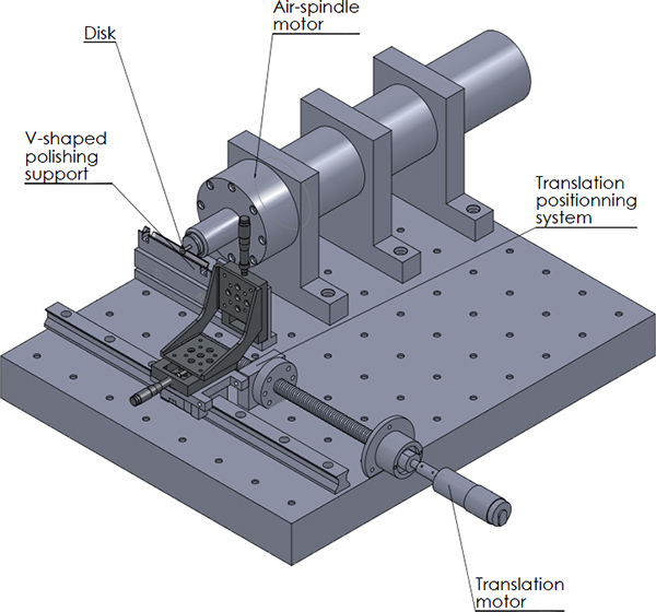 Scheme 1. The customized polishing tower, used to manufacture the WGM ultra-high quality disks.
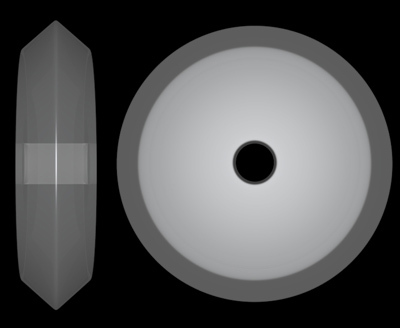 Scheme 2. Software-generated side- and top-view of an optical WGM resonator after grinding. The diameter is typically of the order of 5 mm, while the height is around 1 mm. The central hole enables to hold and manipulate the disk using a stub, without touching the rim. Starting from a plain disk (which is cylindrical), the polishing process grinds the outer part in a V-shaped fashion.
 Scheme 3. Experimental setup for Kerr comb generation. Light from a tunable laser diode is amplified and launched into the WGM resonator via the tapered fiber. The output signal is either collected on a photodiode to monitor the signal on an oscilloscope or to extract the beat-note signal or on a high-resolution optical spectral analyzer for observation of the Kerr comb.
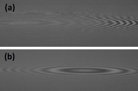 Figure 1. White light interferogram patterns of a WGM resonator at two different steps of the grind-and-polish protocol: the first one was taken after the 1 μm polishing step (a), the second one after the 100 nm polishing (b). The features of the resonator were completely smoothed by the successive polishing operations.
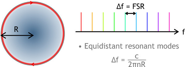 Figure 2. Top-view of the spatial representation of a torus-like WGM that is trapping light by total internal reflection. This WGM disks supports thousands of quasi-equidistant resonant modes (whenever belonging to the same family of eigenmodes). They have a free-spectral range (FSR) of the order of 10 GHz for mm-size disks.
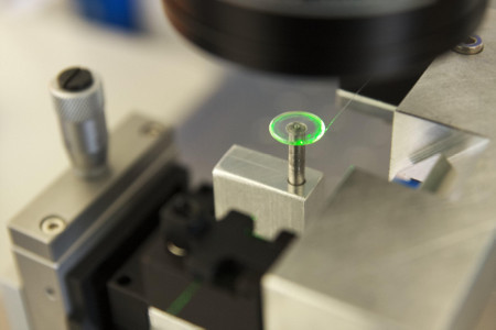 Figure 3. Coupling of visible light in a WGM resonator. The coupling is effective since the green light guided by the fiber taper is illuminating the resonator.
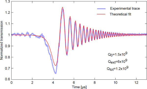 Figure 4. Cavity ring-down signal from a WGM resonator. The fitting curve gives the intrinsic and coupling photon lifetimes in the cavity, which are directly proportional to the quality factor of the resonator. Here, an intrinsic quality factor of 1.5 x 10⁹ has been achieved.
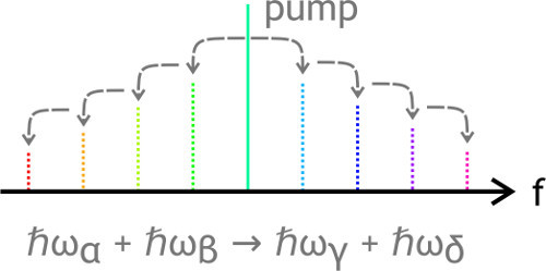 Figure 5. Kerr comb generation mechanism in WGM resonators. When a cavity mode is pumped above a given threshold with a resonant laser, the photons are coherently distributed to the neighboring side-modes through four-wave mixing, which may involve any four photons α, β, γ, and δ, fulfilling the conditions of energy and momentum conservation. This is a direct consequence of the Kerr effect, which induces a quadratic change in the refraction index relatively to the intra-cavity electric field.
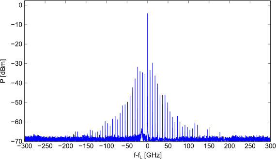 Figure 6. Experimental Kerr optical frequency comb. The central frequency fL is the frequency of the input laser, around 193.3 THz. The other spectral lines are created by the nonlinear interactions in the resonator. The frequency between each spectral line is 6 GHz, corresponding to the free spectral range of the resonator.
Discussion
This protocol allows producing high-Q optical resonators, to couple light into them and trigger nonlinear phenomena for various microwave photonics applications.
The first step of rough grinding should give its shape to resonator. After an hour of grinding with the 10 μm abrasive powder, one side of the rim of the resonator should be conveniently shaped (see Scheme 2). The following step will smooth the surface of the resonator and when reaching the stage of the 1 μm-diameter abrasive powder, its surface should be transparent. This is called an optical polish. However, this is not enough to get a high quality factor and extra steps are needed with smaller abrasive particles to achieve a better surface quality with nanometer-scale roughness. We use a white light interferometric profilometer to measure the surface irregularities which lead to surface scattering-induced losses and thereby lower the Q factor performance. This step is an important experimental test to evaluate the quality of the polishing. Figure 1 shows two pictures taken with a profilometer at two different steps of the process. The first one is taken after the grinding step, showing an irregular surface with a perturbed interference pattern. However, after the polishing step, the interference pattern is smooth and regular, revealing that the surface state of the resonator is smooth at the 10 nm-scale. This is what should be looked for in order to obtain high-Q resonators. It is also important to note that this angle-shape for the rim has to be optimized in order to allow for the highest modal confinement without inducing too much mechanical stress during the grinding steps.
The taper-drawing protocol requires a little fine-tuning in order to obtain low transmission loss. This highly depends on the blowtorch used, but the distance from the fiber to the flame should be such that the heating zone is the widest. Typical value for the constant acceleration parameter is around 5 μm.s-2, but it should be adapted to each flame power and to the shape of the taper to be drawn.
Approaching the resonator to the tapered fiber is also a process that should be very well controlled through the use of a micrometer-resolution translation stage, and monitored with a binocular microscope. The vertical alignment and tilt angle are also critical for obtaining a good coupling and a high-quality factor. Once the coupling is efficient (see Figure 2), the transmission spectrum can be obtained using a wavelength-tunable laser in the scanning mode. If the sweeping is fast enough and the quality factor of the resonator sufficiently high, the transmitted signal should behave as seen in Figure 3. By fitting this experimental curve, we are able to extract the intrinsic quality factor of the resonator.
It should be noted that other means of coupling light in the resonator are possible, namely with a prism27 or angle-polished fibers28. Both methods make use of the evanescent field of a reflected beam on the interface between glass and air. The advantage of these methods is that the coupling is more stable; however, the alignment needed in both cases is much more difficult to obtain compared to the taper method. The efficiency of the tapered fiber coupling is also greater (up to 99.9%15) than what can be achieved with prism and angle-polished fiber coupling.
The nonlinearity in the resonator can be excited with a high pump power. The well-known process of four-wave mixing produces sharp spectral lines in the resonator separated by a well-defined constant: the resonator's free spectral range (or an integer multiple). Using a fast photodiode and a band pass filter, one can extract this precise fixed frequency gap to generate a low noise microwave signal generator. However, this process normally requires sophisticated feedback loops for signal control and stabilization, which have not been considered here for the sake of exemplification29.
Disclosures
The authors declare that they have no competing financial interests.
Acknowledgments
Y.C.K. acknowledges financial support from the European Research Council through the project NextPhase (ERC StG 278616). Authors also acknowledge support from the Centre National d'Etudes Spatiales (CNES, France) through the Project SHYRO (Action R&T R-S10/LN-0001-004/DA: 10076201), from the ANR project ORA (BLAN 031202), and from the Region de Franche-Comte, France.
References
- Oraevsky AN. Whispering-gallery waves. Quantum Electronics. 2002;32:377–400. [Google Scholar]
- Matsko AB, Ilchenko VS. Optical Resonators With Whispering-Gallery Modes-Part I: Basics. IEEE J. Sel. Top. Quantum Electron. 2006;12:3–14. [Google Scholar]
- Ilchenko VS, Matsko AB. Optical Resonators With Whispering-Gallery Modes-Part II: Applications. IEEE J. Sel. Top. Quantum Electron. 2006;12:15–32. [Google Scholar]
- Maker AJ, Armani AM. Fabrication of Silica Ultra High Quality Factor Microresonators. J. Vis. Exp. 2012. p. e4164. [DOI] [PMC free article] [PubMed]
- Savchenkov AA, Matsko AB, Ilchenko VS, Maleki L. Optical resonators with ten million finesse. Optics Express. 2007;15:6768–6773. doi: 10.1364/oe.15.006768. [DOI] [PubMed] [Google Scholar]
- Sprenger B, Schwefel HGL, Lu ZH, Svitlov S, Wang LJ. CaF2 whispering-gallery-mode-resonator stabilized-narrow-linewidth laser. Optics Letters. 2010;35:2870–2872. doi: 10.1364/OL.35.002870. [DOI] [PubMed] [Google Scholar]
- Vahala K, editor. Optical Microcavities. Singapore: World Scientific; 2004. [Google Scholar]
- Matsko AB, Savchenkov AA, Yu N, Maleki L. Whispering-gallery-mode resonators as frequency references. I. Fundamental limitations. J. Opt. Soc. Am. B. 2007;24:1324–1335. [Google Scholar]
- Savchenkov AA, Matsko AB, Ilchenko VS, Yu N. Whispering-gallery mode resonators as frequency references. II. Stabilization. J. Opt. Soc. Am. B. 2007;24:2988–2997. [Google Scholar]
- Chembo YK, Baumgartel LM, Yu N. Toward whispering-gallery mode disk resonators for metrological applications. SPIE Newsroom. 2012.
- Armani DK, Kippenberg TJ, Spillane SM, Vahala KJ. Ultra-high-Q toroid microcavity on a chip. Nature. 2003;421:925–929. doi: 10.1038/nature01371. [DOI] [PubMed] [Google Scholar]
- Hofer J, Schliesser A, Kippenberg TJ. Cavity optomechanics with ultrahigh-Q crystalline microresonators. Phys. Rev. A. 2010;82:031804. [Google Scholar]
- Fürst JU, Strekalov DV, Elser D, Aiello A, Andersen UL, Marquardt Ch, Leuchs G. Quantum Light from a Whispering-Gallery-Mode Disk Resonator. Phys. Rev. Lett. 2011;106:113901-1–113901-4. doi: 10.1103/PhysRevLett.106.113901. [DOI] [PubMed] [Google Scholar]
- Del'Haye P, Schliesser A, Arcizet O, Wilken T, Holzwarth R, Kippenberg TJ. Optical frequency comb generation from a monolithic microresonator. Nature. 2007;450:1214–1217. doi: 10.1038/nature06401. [DOI] [PubMed] [Google Scholar]
- Kippenberg TJ, Holzwarth R, Diddams SA. Microresonator-Based Optical Frequency Combs. Science. 2011;322:555–559. doi: 10.1126/science.1193968. [DOI] [PubMed] [Google Scholar]
- Spillane SM, Kippenberg TJ, Vahala K. Ultralow-threshold Raman laser using a spherical dielectric microcavity. Nature. 2002;415:621–623. doi: 10.1038/415621a. [DOI] [PubMed] [Google Scholar]
- Liang W, Ilchenko VS, Savchenkov AA, Matsko AB, Seidel D, Maleki L. Passively Mode-Locked Raman Laser. Phys. Rev. Lett. 2010;154:143903-1–143903-4. doi: 10.1103/PhysRevLett.105.143903. [DOI] [PubMed] [Google Scholar]
- Grudinin IS, Matsko A, Maleki L. Brillouin lasing with a CaF2 whispering gallery mode resonator. Phys. Rev. Lett. 2009;102:043902-1–043902-4. doi: 10.1103/PhysRevLett.102.043902. [DOI] [PubMed] [Google Scholar]
- Werner CS, Beckmann T, Buse K, Breunig I. Blue-pumped whispering gallery optical parametric oscillator. Optics Letters. 2012;37:4224–4226. doi: 10.1364/OL.37.004224. [DOI] [PubMed] [Google Scholar]
- Knight JC, Cheung G, Jacques F, Birks TA. Phase-matched excitation of whispering gallery-mode resonances by a fiber taper. Opt. Lett. 1997;22:1129–1131. doi: 10.1364/ol.22.001129. [DOI] [PubMed] [Google Scholar]
- Chembo YK, Yu N. Modal expansion approach to optical-frequency-comb generation with monolithic whispering-gallery-mode resonators. Phys. Rev. A. 2010;82:033801-1–033801-18. doi: 10.1103/PhysRevLett.104.103902. [DOI] [PubMed] [Google Scholar]
- Chembo YK, Strekalov DV, Yu N. Spectrum and Dynamics of Optical Frequency Combs Generated with Monolithic Whispering Gallery Mode Resonators. Phys. Rev. Lett. 2010;104:103902-1–103902-4. doi: 10.1103/PhysRevLett.104.103902. [DOI] [PubMed] [Google Scholar]
- Chembo YK, Yu N. On the generation of octave-spanning optical frequency combs using monolithic whispering-gallery-mode microresonators. Opt. Lett. 2010;35:2696–2698. doi: 10.1364/OL.35.002696. [DOI] [PubMed] [Google Scholar]
- Brown NJ. Report MISC 4476 1LLNL. Lawrence Livermore National Laboratory; 1990. Optical fabrication. [Google Scholar]
- Strekalov DV, Savchenkov AA, Matsko AB, Yu N. Efficient upconversion of subterahertz radiation in a high-Q whispering gallery resonator. Optics Letters. 2009;34:713–715. doi: 10.1364/ol.34.000713. [DOI] [PubMed] [Google Scholar]
- Dumeige Y, Trebaol S, Ghisa L, Ngan Nguyen TK, Tavernier H, Feron P. Determination of coupling regime of high-Q resonators and optical gain of highly selective amplifiers. J. Opt. Soc. Am. B. 2008;12:2073–2080. [Google Scholar]
- Gorodetsky ML, Ilchenko VS. Optical microsphere resonators: optimal coupling to high-Q whispering-gallery modes. J. Opt. Soc. Am. B. 1999;16:147–154. [Google Scholar]
- Ilchenko VS, Yao XS, Maleki L. Pigtailing the high-Q microsphere cavity: a simple fiber coupler for optical whispering-gallery modes. Opt. Let. 1999;24:723–725. doi: 10.1364/ol.24.000723. [DOI] [PubMed] [Google Scholar]
- Del'Haye P, Arcizet O, Schliesser A, Holzwarth R. Kippenberg T.J. Full stabilization of a microresonator frequency comb. Phys. Rev. Let. 2008;101:053903. doi: 10.1103/PhysRevLett.101.053903. [DOI] [PubMed] [Google Scholar]


