Abstract
We live in a world of convergence where scientific techniques from a variety of seemingly disparate fields are being applied cohesively to the study and solution of biomedical problems. For instance, the semiconductor processing field has been primarily developed to cater to the needs of the ever decreasing transistor size and cost while increasing functionality of electronic circuits. In recent years, pioneers in this field have equipped themselves with a powerful understanding of how the same techniques can be applied in the biomedical field to develop new and efficient systems for the diagnosis, analysis and treatment of various conditions in the human body. In this paper, we review the major inventions and experimental methods which have been developed for nano/micro fluidic channels, nanoparticles fabricated by top-down methods, and in-vivo nanoporous microcages for effective drug delivery. This paper focuses on the information contained in patents as well as the corresponding technical publications. The goal of the paper is to help emerging scientists understand and improvise over these inventions.
Keywords: Nanomedicine, nanofabrication, lithography, drug delivery, nanoparticle, nanochannels, cell encapsulation, microcages
I. INTRODUCTION
The challenges that face the medical field, including food and health safety, and national security, can be effectively answered using new devices that have fast response times, high sensitivity and specificity, and the flexibility to help realize the goals of personalized medicine. In particular, during the last decades, nanoscale devices and materials have emerged as powerful technologies to deliver breakthrough performance in drug delivery, biosensing, and diagnostics. To achieve high performance and practical use of these nanodevices and nanomaterials would require precise and cost effective manufacturing methods, thereby ushering in a new era of nanofabrication.
In the field of nanofabrication, a variety of top-down and bottom-up methods have been developed to cater to the needs of both down-scaling of semiconductor devices and also emerging nanotechnology applications. Most nanofabrication methods have been extensively discussed and summarized in several review articles [1, 2]. In this review paper, we are particularly interested in the new application of top-down methods, that were mainly developed for fabricating semiconductor devices, to new areas of nanomedicine. These new inventions are based on top down methods of photolithography, nanoimprint lithography (NIL), electron beam lithography (EBL), and interference lithography. Moreover, bottom-up approaches employing self assembling molecules are based on chemical techniques and are being combined with top-down methods to increase accuracy as well as to decrease cost and production time. We detail how some of these methods may be adapted for nanomedicine applications.
Notably, conventional lithographic methods are conducted in an environment that is often too hostile for biocompatibility and biological applications. Therefore, we highlight how some of these approaches, such as nanoimprint lithography and photopolymerization of device components, may be performed in a biofriendly manner.
In the first section of this paper, we review inventions that provide methods of fabrication and application of nanochannels to the field of diagnostics. Such nanochannels provide confined environments for the isolation and analysis of biomolecules. These structures may be combined with other devices at the nanoscale level to achieve system functionality for applications in both life science and medical diagnostics.
The second section focuses on the fabrication of nanoparticles for nanomedicine applications. The effects of particle shape and size of non-spherical particles with respect to circulation, extravasation and distribution in vivo for targeted drug delivery and imaging will be discussed. We will present the recent advances in the bio-compatible fabrication of shape-specific nanoparticles and their unique biological and pharmacological properties.
The final section of this paper deals with nanoporous microcages that provide an immunoprotective environment for therapeutic, bio-engineered donor cells to aid in the treatment of hormonal deficiencies and diseases.
II. NANOCHANNELS
A. Introduction
Detection and analysis of various biological substances are important for applications related to health, food safety and national security. Micro- and nano-fluidic chips and lab-on-a-chip have emerged as one of the most promising approach to enable low cost, rapid, and portable detection or analysis of biological molecules for point-of-care diagnostics. Some of the diagnostic assays created using semiconductor fabrication techniques centre on the use of nanochannels. Most genetic disorders are hard to study and treat because of the lack of information about the DNA strands where they originate.
DNA is a double stranded helical structured molecule with a backbone of phosphate and sugar groups linked by ester bonds between the two strands. The thickness of the DNA molecule itself is about 2 nm and it normally exists in a coiled configuration. With such a configuration the DNA is defined by the radius of gyration which can range in the order of 700 nm to a few micrometers. Another measure is the stiffness of the DNA molecule which is defined as the persistence length. The radius of gyration in turn depends on the persistence length as well as the contour length of the DNA molecule.
The initial studies that were conducted were concerned with how to develop nanofabricated structures to untangle and elongate the DNA molecule so as to enable ease of analysis. In this regard, nanochannels have been primarily used to elongate DNA molecules due to the fact that DNA molecules do not require any external force to keep them elongated in such channels and the molecule exists in equilibrium in its stretched state.
Because of thermal effects it has been shown by DeGennes that the DNA molecule undergoes length fluctuations to develop kinks and blobs in its structure. The effective length of the DNA varies linearly with the contour length [3]. It has been shown that when the width of the channel decreases beyond the radius of gyration of the unfolded molecule, the relationships begin to vary. Thus the effective length increases as we decrease the width of the nanochannel. Recent fabrication methods such as nanoimprint lithography [4], interferometric lithography [5], electron beam and ion beam lithography have enabled fabrication of nano-channels with less than 100nm dimensions.
It is energetically unfavorable for coiled DNA molecules to spontaneously elongate due to the large free energy needed to overcome the negative entropy change, this was overcome by the invention of gradient structures comprising of micro/nanopillars which interfaced the microfluidic region to the nanochannel region by Cao et al. [6]. Also it was shown by Schwartz et. al. that decreasing the ionic strength of the solution in which the DNA molecules have been suspended significantly decreases the persistence length [7] making the DNA molecule more pliable.
DNA is extremely sensitive to environmental variations and there is a need to preserve the ambient conditions. This has been addressed in a patent by Chou et al. [8] where they have provided a method of creating a transparent sealing layer made of Silicon Dioxide. The transparency enables imaging analysis of the confined bio-molecule.
In the next section we will take a closer look at the inventions mentioned above to reveal the details of fabrication methods, experimental results and possible challenges.
B. Current Inventions
Nanochannels can be fabricated in a variety of ways. It can be observed that after the advent of recent unconventional lithography techniques the fabrication of nanochannels having widths less than 100 nm and depths less than 200 nm required for macromolecular analysis has become more feasible. The general structure of nanochannel devices contains three parts: i) sample reservoirs for loading sample solutions; ii) nanochannels equipped with devices for analysis and imaging; iii) waste reservoirs to collect the sample solutions after analysis.
1). Sealed Nanochannel Arrays for High Throughput Macromolecular Analysis [8]
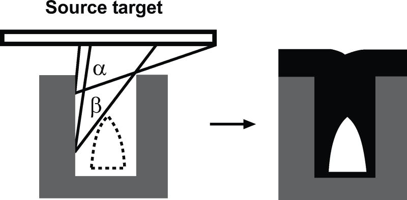
One of the first inventions was by Chou et al. Their invention consisted of nanochannels fabricated by photolithographic techniques or NIL. The key technique of the patent was the controlled deposition of the sealing layer. The channels can be completely sealed as shown in Fig. (1) using sputtering deposition of sealing materials onto the pre-patterned trenches. The objective of the sealing layer is to enable size reduction of channels and to protect the bio-molecule.
Fig. (1).
a) A schematic illustration of the sputtering deposition process to form sealed nanochanels on prepatterned nano-trenches utilizing structural shadow effects. b) Schematic cross-section of sealed nanochannel array after depositing sealing material by sputtering (schematic redrawn from ref. [8]).
This method provides great fabrication simplicity. The nanochannels are first fabricated using photolithography or nanoimprint lithography. The sealing of the nanochannels at top is achieved by oblique angle deposition of SiO2 using either tilted e-beam evaporation or sputtering. Using the self-shadowing effects caused by the nanochannels and evaporation methods, uneven profile of deposited materials can be achieved to seal the top of the channels while it has less deposition into the nanochannel, as shown in Fig. (1).
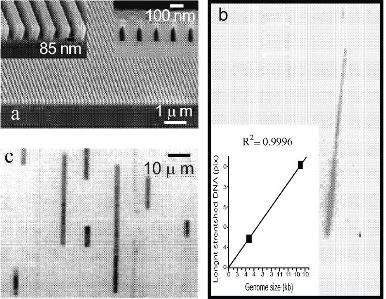
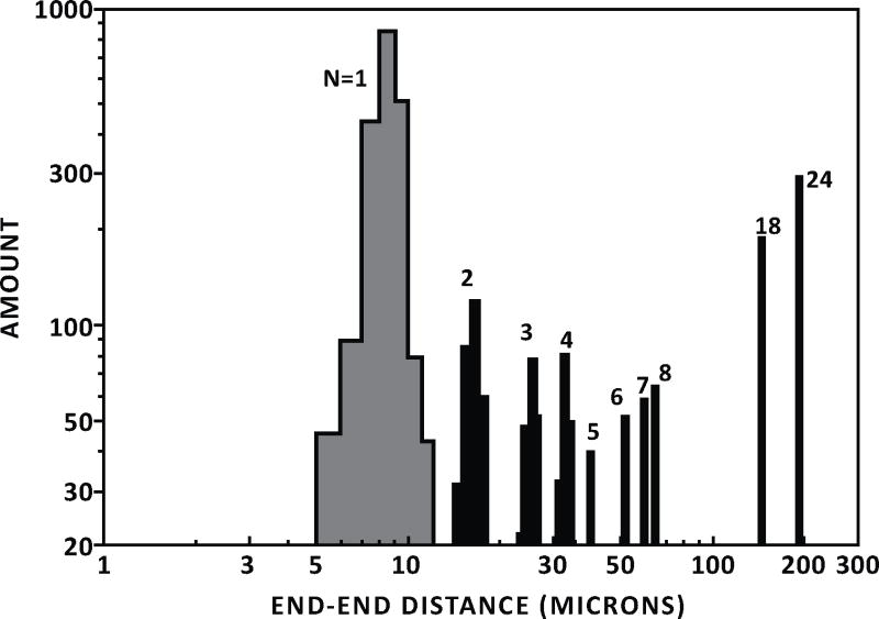
The nanochannels created using this method have been applied to measure directly the contour length of single DNA molecules confined in the channels, as shown in Figs. (2, 3). And the statistical analysis of the dynamics of the polymer in the nanochannel allows them to compute the standard deviation (SD) of the mean of the extension. This statistical analysis allows them to measure the extension of λ DNA multimers with a 130-nm SD in 1 min, as shown in Fig. (3) [9].
Fig. (2).
a) Scanning electron micrograph of the substrate (left and bottom) and the seal nanochannel array); b) CCD image of 48.5kb lambda phage genome (shorter one) and 168 kb T4 phage genome (longer) along with a plot of contour length vs genome size; c) nanochannel array displaying a plurality of elongated DNA molecules in size range of 10kb to 196kb [8].
Fig. (3).
A histogram of end-to-end distances of DNA molecules observed in the 100-nm-width nanochannels vs the amount of DNA is shown [9].
2). 3D Gradient Structures Interfacing Nanofluidics
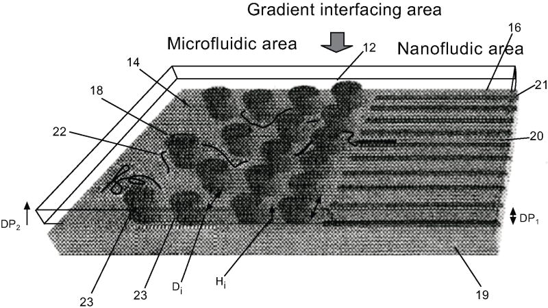
The DNA needs to be unfolded to an extent before it can successfully enter the nanochannel. In order to address this issue, Cao Han et al. have demonstrated a gradient structure where they have used an array of micropillars whereby the spacing between them decreases as we approach the nanochannel, as shown in Fig. (4) [6]. The micro-posts have varying distances between them, starting from the radius of gyration of a DNA molecule (700nm) to the width of a DNA molecule (2nm). This provides a gradient of the entropy change allowing the macromolecule to slowly elongate before they can enter the nanochannels.
Fig. (4).
Schematic diagram showing the gradient interfacing region between the microfluidic and nanofluidic regions of the invention [6].
The gradient interface in this invention can be fabricated using diffraction gradient lithography [6]. Diffraction gradient lithography is a technique where a blocking mask is placed above the conventional mask in photolithography (Fig. 5a). During the UV exposure, the edge of the blocking mask will diffract the incident lights, creating a diffraction pattern with varying light intensity profile in the photo resist, as shown in Fig. (6A). During the development process, only a portion of the photoresist will develop due to partial exposure (Fig. 5b). This 3D gradient photoresist structure is then used as a mask for the sequential etching step to transfer such structures into the substrate, e.g. Si. The resulting structures after photoresist development and after etching are shown in Fig. (6).
Fig. (5).
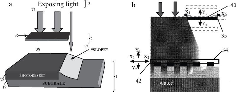
a) Schematic showing the working mechanism of Diffraction Gradient Lithography (DGL), b) Schematic showing a method of adjusting the diffraction gradient using variations in distance [6].
Fig. (6).
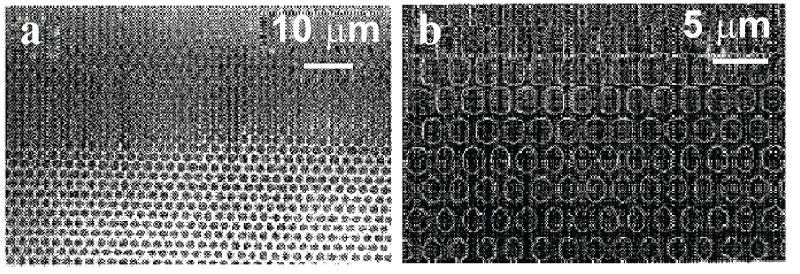
a) Optical image of the sample after resist development. b) Optical image of the sample after pattern transfer and photo resist removal [6].
3). Detection of Microscopic Pathogens Using Micro- Nanochannel Based Assays [10]
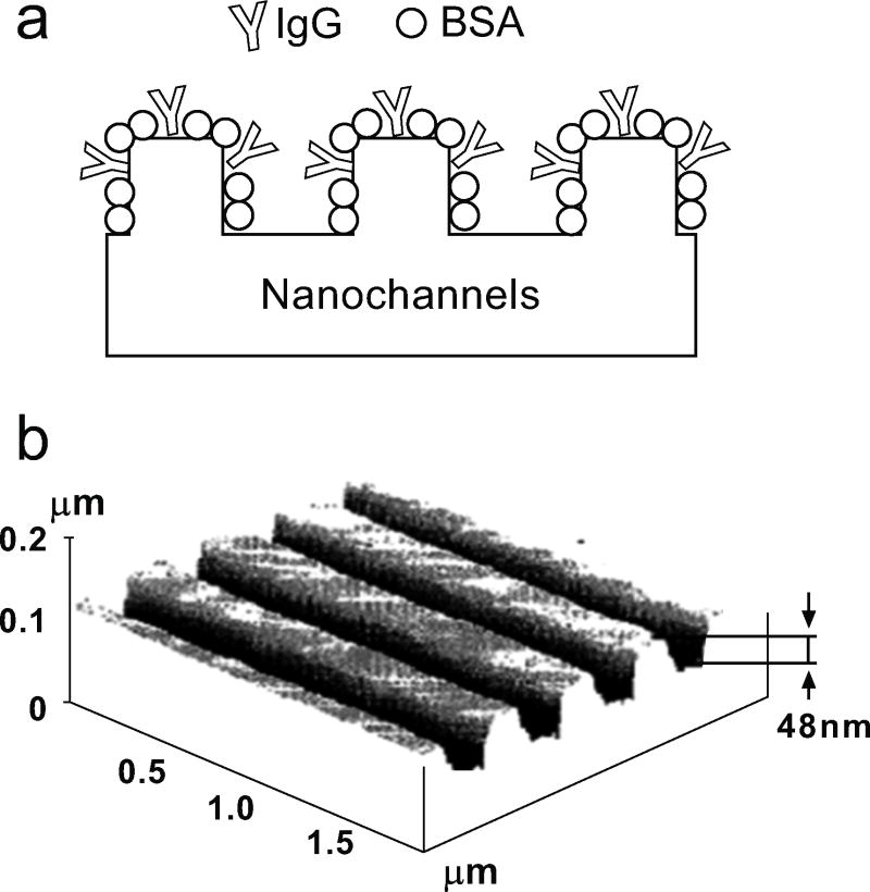
Detection of biomolecules is also an important realm to examine. There are various techniques used to detect the presence of certain pathogens. One of these innovative techniques was invented by Abbott et al. The main idea is to use the presence of a specific pathogen to induce a disruption in the alignment of the liquid crystal, as shown in Fig. (7). The entire surface of the micro/nanochannel is coated with a blocking agent like Bovine serum albumin (BSA) which does not bind to any pathogen. At specific sites the channels are coated with a binding agent which specifically binds only to certain pathogens. Then the entire structure is filled with liquid crystal. The blocking agent does not cause any disruption in the alignment of the liquid crystal. But when a pathogen binds to its specific binding agent it creates a disruption of this alignment which can easily be detected by a microscope. Hence this invention provides a means of speedy diagnosis against multiple threats simultaneously. The recent work and patents filed by the same group have demonstrated detection of EGFR and other ligands using this method [United States Patent 8133680]. The method can also be applied to detect other biomolecules and also gas detection [US Patent 8,178,355, 2012].
Fig. (7).
a) Schematic of the patterned nanochannels with blocking layer and binding agents within to bind the specific pathogen (schematic redrawn from ref. [10]); b) an AFM image of a silicon master used to form nanochannels [10].
The channels were made by soft lithography using PDMS molds as shown in Fig. (7a). Different kinds of thermally and UV-curable polymers were used to create the replica patterns on a glass substrate. Additionally a gold coating of ~10nm was applied to the surface of the microstructures to anchor self-assembled monolayer (SAM) from alkanethiols. The alignment of the liquid crystal 5CB was tested out on different substrates. BSA was chosen as the passivation material due to its small size so that it does not disrupt the crystal orientation. Magnetic beads can also be used to link with the pathogen to aid in better imaging analysis.
III. TOP-DOWN NANOPARTICLES
A. Introduction
Conventional methods of making nanoparticles in the pharmaceutical industry use the bottom-up approach [11–14]. In general, the bottom up approach has the main disadvantage that the particle size and shape cannot be controlled accurately since the populations of particles fabricated are poly-dispersed. Although there is significant progress to improve the controllability of chemical synthesis to achieve monodisperse particles, the uniformity and accuracy is still not as good as lithography methods. Other issues for bottom-up approaches include lack of control of the stimuli-responsiveness, poor encapsulation, and difficulty of achieving multiple functionalities with the same structure. Top-down methods offer effective control of particle size and also enable the exact design of the particle shape offering multi-functionality. Such particles can be engineered to contain a wide variety of substances from therapeutic agents to magnetic nanoparticles thus catering to diagnosis, targeting, and treatment. Studies [15] have shown that particle size can dramatically impact on the efficacy of drug delivery. Nanoparticles with the size of 10–200nm are ideal for drug delivery as they pass through all the filtration systems in the body such as spleen. Recently studies [16–18] have also shown that the particle shape can be a very important factor. The shape is critical since the responses of human macrophages and adhesion probabilities to tumor cell sites are based on the same. For intravascular vessels the particles prefer to have a disc like shape with diameters ranging between 0.05 to 5 microns [19]. This effectively increases the circulation time thus reducing the dosage and also enabling a longer window for diagnosis. Shape also considerably affects the drug payload capability and performance in blood circulation, targeting etc and increase detection sensitivity [15]. Virus is an excellent example of this phenomenon. Normal virus cells have a wide variety of non-spherical shapes which prevents them from being consumed by phagocytosis. It has also been shown that such particles have an extended life time [16–18].
Top-down fabrication processes employ bio-compatible material like SU-8, polyethylene glycol (PEG), etc. Conventional lithographic processes such as photolithography have reached the resolution limits and it is not possible for fabricating particles less than 50nm in a cost effective manner. New techniques such as particle replication in a non-wetting template (PRINT), step and flash imprint lithography (S-FIL), template induced printing (TIP) have been developed to make nonspherical particles, as reviewed in ref. [15]. All of the above processes are variations of nanoimprint lithography (NIL). The main problem with nanoimprint lithography is the formation of residue. After de-molding of the template from the resist layer, a residual layer connecting the structures is left on the substrate. Some of these techniques offer the advantage of overcoming this, for example in TIP we use a bi-layer resist say PMMA and SU-8. The bottom layer acts as a sacrificial layer and can be chemically removed without requiring reactive ion etching which usually damages the bio-polymers. Various fabrication methods have been extensively discussed in our recent mini review paper [15] and it is summarized in Table 1.
Table 1.
A Brief Review of the Various Fabrication Methods Used for Fabrication of Shape-Specific Nanoparticles [15]
| Fabrication Techniques | Shapes | Smallest Dimension | Matrix Materials | Incorporated Functional Agents | References | |
|---|---|---|---|---|---|---|
| Top-down approach | PRINT® | Cube, rod, circular disc, cone, hex-nut | 100 nm | PEGDA, PLA, PPy, triacrylate, natural proteins | Cy3 dye, doxorubicin, Fe2O3, DOTA, protein | [34–39] |
| Stretching Spherical Particles | Elliptical disc, oblate or prolate ellipsoid, worm, UFO | 200 nm | Polystyrene, PLGA | FTIC-labeled bovine serum albumin | [40–42] | |
| Step-flash imprint lithography | Square, triangle, pentagon | 50 nm | PEGD (M)A, PEGDA-GFLGK-DA | Streptavidin-Cy5 fluorescent dye, plasmid DNA | [43] | |
| Template Induced Printing (TIP) | Circular disc, bullet, rod, long worm | 80 nm | SU-8, PEGDA, PEG-b-PLA | BODIPY® 493/503 fluorophore, SPIO (Fe3O4) | [44–46] | |
| Bottom-up approach | Self-assembly | Long worm | 22~60 nm | OE, OCL | Paclitaxel | [24] |
| Worm | 5 nm | Fe2O3 | N/A | [27] | ||
| Emulsion | Ellipsoid | 28 nm | F8BT, PFO | N/A | [47] | |
PEGDA, polyethylene glycol diacrylate; PLA, poly(D,L-lactic acid); PPy, poly(pyrrole); PLGA, poly(D,L-lactic acid-co-glycolic acid); PEGDMA, polyethylene glycoldimethacrylate; PEGDA-GFLGK-DA, poly(ethylethylene glycol diacrylate-co-acrylated Gly-Phe-Leu-Gly-Lys); PEG-b-PLA, poly(ethylene glycol)-co-poly(D,L-lacticacid); OE, PEG-polyethylene; OCL, PEG-poly(1-caprolactone); F8BT, poly(9,9-dioctylfluorene-cobenzothiadiazole); PFO, poly(9,9-dioctylfluorene); Gd-DOTA,Gd-1,4,7,10-tetraazacyclododecane-1,4,7,10-tetraacetic acid; SPIO, superparamagnetic iron oxide; UFO, unidentified flying object.
Such nanoparticles are engineered to respond to the physiological stimuli present in the body and undergo a structural disintegration to release the drugs inside. The particle may be degradable by an enzyme that is specifically expressed/present in the diseased state. Ligands and biomolecules specific to the diseased cell can be applied onto the surface of the particles. The specificity is based on the fact that such cells express certain factors on the surface, for example tumor cells normally have an over-expression of growth factors on their surface [20]. Imaging particles can be added along with the therapeutic agents to simultaneously assess the impact of the devices.
The aim of this section is to review the various inventions in nanoparticle fabrication by top-down methods and to develop a broader understanding of the applications of semiconductor processing methods in the pharmaceutical field.
B. Current Inventions and Findings
1). Therapeutic Microdevices [19]
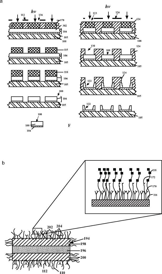
This is one of the first patents in the nanoparticle fabrication realm and uses a top-down lithographic approach. The patent describes fabrication methods of nanoparticles with a wide variety of shapes based on the intended drug delivery sites. As shown in the Fig. (8a), the first step consists of four layers, with a sacrificial silicon dioxide layer at the bottom, followed by a laminate expanse, made of PEG or other suitable materials as desired by the application, that is attached to this sacrificial layer. This entire structure is spin coated with a photoresist, followed by photolithography and etching to form the structures in the functional layer. The particles can be released by dissolving the sacrificial layer. As shown in Fig. (8b), the bottom layer of the particles is normally coated with target-specific antibodies and therapeutic agent or imaging agent is contained within the nanoparticle. For intravascular vessels the particles need to have a disc like shape with diameters ranging between 0.05 to 5 microns. The patent covers nanoparticles made from different types of biodegradable materials, metals and alloys. They are engineered to be activated based on one or more external stimuli including magnetic, optical, ultrasonic, etc. Additionally the particles can have multiple functional layers with an outer coating of PEG to increase the hydrophillicity, solubility and therefore the lifetime of the nanoparticles.
Fig. (8).
a) Illustrated steps of the photolithographic fabrication of microstructures as proposed in the patent [19] b) Schematic figure of the trilaminate microstructure with therapeutic agent containing layer sandwiched between two targeting or support layers. The inset shows exposed regions of the target or support layers coated with hydrophilic molecules and the target-specific binding molecules [19].
2). Fabricating Nano and Microparticles for Drug Delivery [42]
This patent deals with fabricating nano or microparticles which hold the required treatment drugs using a top-down approach. The top down approach enables the creation of a monodisperse population (as in same shape, size and mass).
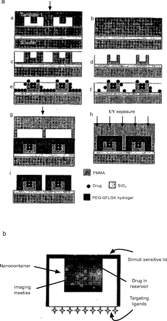
A nanofabricated device needs to be less than 300 nm in size to be incorporated into a tumor cell. The need for a 3D structure for encapsulation has favored the use of Step and Flash Imprint Lithography(S-FIL) and NIL, as shown in Fig. (9). Two Imprint templates were made from silicon using electron beam lithography and reactive ion etching techniques. The substrate is a Si wafer with a 100nm SiO2 layer on top. The first imprint transferred the pattern into a PMMA coating after which it was loaded with the therapeutic agent. The second imprint transferred the lid structure made of PEG based hydrogel to seal the PMMA structure. The release of the nanoparticles is done by HF etching of SiO2 layer or by soaking in DI water for a long time. The latter approach takes advantage of the fact that Silicon dioxide has poor adhesion with polymers.
Fig. (9).
a) schematic views of the processing steps for a thermal and S-FIL based nanoimprint fabrication process of PMMA lidded particles with PEG-peptide-PEG lids. b) Schematic diagram of a disease-responsive drug delivery nanocontainer [42].
The particle may be degradable by an enzyme that is specifically expressed/present in the diseased state. Examples of biodegradable polymers used are poly(lactic-co-glycolic acid or PLGA. Targeted delivery can be achieved by attaching target-specific ligands to the surface of nanoparticles. Imaging particles can be added along with the therapeutic agents to simultaneously assess the impact of the devices. Stimuli sensitive hydrogels can further be used to introduce a stimulus response (degradation) to the nano-containers based on environmental conditions (pH, temperature, external magnetic field). They can also be designed to respond to enzymes eg. PEG-peptide-PEG triblock polymer. Enzyme break down of the polymer is much faster than hydrolytic breakdown. Lids containing these hydrogels should prevent diffusion of the therapeutic agent before they reach the target site.
3). Microfabricated Particles and Method for Treating Solid Tumors [21]
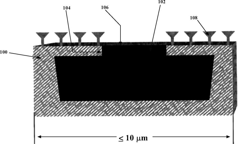
The patent discloses a way in which we can fabricate asymmetric nanoparticles which have a special chemical layer to delay the release of the cytotoxic agent that is contained in the particle. The entire particle is coated with a hydrophilic layer of polyethylene glycol to increase the lifetime of the particle. As shown in Fig. (10), the front face of the particle is coated with reactive amino or thiol groups by plasma discharge or sialylation methods. This layer is used to attach ligands. These ligands are generally tumor targeting cyclic peptides. The key concept is that these ligands may easily attach only to tumor cells since certain growth factors are over-expressed on their surfaces.
Fig. (10).
Structural features of a microparticle as per the invention 100- Contains at least one reservoir filled with a cytotoxic drug 102-a pore or channel connecting the reservoir to the front face 104-Front face 106-erodible material for delayed drug release 108- tumor specific receptors or ligands [21].
The particle is comprised of a pore which is covered by a bio-erodible membrane, e.g. titanium, gold, silver, platinum, on the front face. These layers are fabricated by metal deposition techniques such as sputtering. Targeting ligands are also present on the front face. The membrane covering the pore can also be made semi-permeable, e.g. PEG to water. In such situations the dry drug particles are suspended in a saline solution. Due to osmosis water in the blood vessels enters the particle and when the osmotic pressure is sufficient the particle bursts releasing the solvated drug. In certain cases an excipient can be added to delay the hydration of the dry drug particles. The shape, size and density of the microparticle has been chosen to favor the binding to the tumor cell against the forces which tend to dislodge it. The typical diameter of the particle ranges between 0.5 to 10 microns. It is also intuitive that as the particle gets smaller the easier it is to dissolve it. The microdevices can further be tagged with fluorescent dyes on the outer surface to enable imaging and analysis.
IV. NANOPOROUS MICROCAGES
A. Introduction
So far, we have considered particles or drug delivery systems which are essentially fabricated using 2D methods. However, 3D encapsulation is sometimes desirable or required for the delivery of drugs or cells to a specific physiological site. If the surface of the encapsulation device is appropriately nanoporous, then the encapsulation offers protection to the cell or therapeutic agent from the immune system, in addition to protecting the host from unwanted proliferation or migration of the therapeutic cargo. This protection eliminates the need for immunosuppressant drugs. For cell encapsulation, the surface of the encapsulating device should have sufficient nanoporosity to allow the inflow of nutrients but prevent the inflow of large harmful immune molecules [22]. Such immunoisolative containers were first proposed by Chang et al. [23] in 1960. For encapsulation of therapeutic enzymes of drugs, there should be sufficient surface porosity to allow the drugs to egress the encapsulation system and into the body. There is an abundance of encapsulation techniques based on chemical methods, but they lack precise control over nanoporosity. For instance, the most common chemical method of encapsulation in alignate-hydrogel does not result in uniform pore size, leading to immune components in the microenvironment penetrating and destroying the encapsulated cells [24].
3D platforms, that are capable of cell and drug encapsulation, have been recently developed to be compatible with traditional CMOS process flows so as to enable high yields. These techniques include wafer stacking [38], micromachining [25], molding [26], and self-assembly [27]. Self-assembly methods include surface tension based assembly [28], electroactive polymer actuation [29], electric actuation [30], thermal and shape memory alloy actuation [31], and stress actuation [32].
Most nanofabrication methods can define nanoscale features in a principally 2D manner. Therefore, controlled folding of nanoporous 2D precursors may be used to achieve a hollow 3D microcage with nanoporous surfaces. Biofriendly molecular bonding of component structures may also be used to create a 3D encapsulation space. Below we will summarize a few recent inventions about making these microcages.
B. Current Inventions and Techniques
1). Controlled Folding of Micromachined Structures [33, 34]
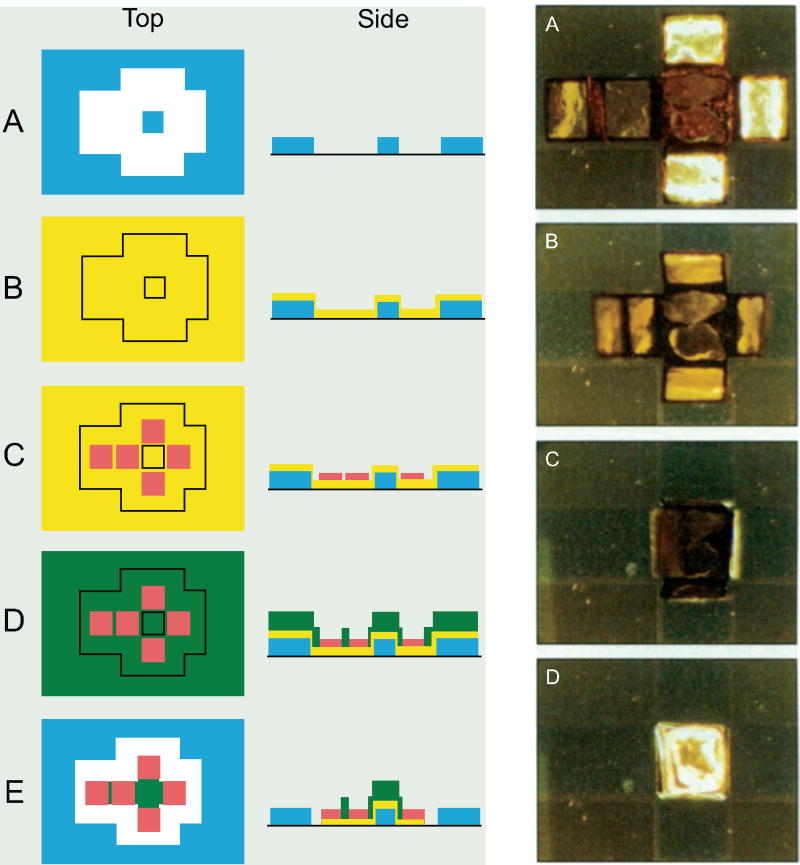
Smela et al. [33, 34] have reported a method to make self-assembling and –disassembling cubes using micro-patterned conducting bilayers, e.g. polypyrrole(PPy) on a layer of gold, as hinges to connect rigid plates.
As shown in Fig. (11), a Au/Cr metal layer is first deposited and patterned on a Si substrate to form two adhesion regions between a membrane and a substrate, i.e. the gold coated area has a weak adhesion to the substrate to enable release of membranes while Cr coated area has a strong adhesion to allow the cube to be fixed on the substrate during folding and unfolding. This concept of differential contact can be used for folding of the membrane with the differential gradient of adhesion, without the use of sacrificial materials. Then, a layer of rigid polymer Benzocyclobuten (BCB) is deposited and patterned to form the faces of cubes. Finally, a critical layer of conducting polymer PPy is deposited and patterned to form the hinges. This PPy polymer has the special property where it can absorb ions from a surrounding electrolytic solution of sodium 4-dodecylbenzenesulfonate (Na+ DBS−) and undergo a volume change based on the bias voltage that is applied. When a positive voltage is applied, the volume of the PPy layer reduces causing a contraction stress to bend the bilayer faces to form cubes. Upon applying a negative voltage, Na+ ions fill in the polymer through oxidation-reduction reactions and cause a volume expansion for the PPy to return to its original size and the cube unfolds. Therefore, by varying the voltages applied to the working electrode, the folding and unfolding of the cubes can be reliably controlled. Fig. (11, right) shows the images of the controlled folding of the cube.
Fig. (11).
(left): Processing sequence for self-opening and self-closing boxes. (A) A layer of chromium (blue) is evaporated onto a silicon wafer and patterned. (B) A gold film (yellow) is evaporated onto the surface. (C) A passive, rigid polymer, BCB, is deposited on the surface by spin-coating and is patterned; (D) PPy (green) is grown electrochemically onto the gold electrodes. (E) The PPy and gold are patterned. Fig. 16 (right): A sequence of photographs shows a cubic box as it closes (A to D). Each of the six sides of the boxes is 300 um by 300 um. The two enclosed particles are small grains of sand. Folding from (A) to (D) took about 1s (adopted from ref. [34]).
2). Self-Assembled, Micropatterned, and Radio Frequency (rf) Shielded Biocontainers and their Uses for Remote, Spatially Controlled Chemical Delivery [35, 36]
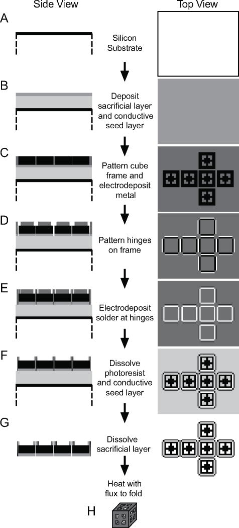
This invention utilizes the property of surface energy to self-assemble encapsulating structures, i.e. the surface energy dictates the shape to which the structure conforms. 2D structures are made with freely moving hinged parts – the melting of the hinges results in the structure folding so as to achieve an energy minimum, as shown in Fig. (12). The lowering of energy during the melting of hinges results in a torque, which in turn rotates the movable structures.
Fig. (12).
A schematic of the basic steps involved in the fabrication of hollow, patterned cubic containers. (A, B) First, a silicon wafer is spin-coated with PMMA, which acts as a sacrificial layer. This is followed by evaporation of Cr and Cu. Cr promotes the adhesion of Cu, while Cu acts as a conductive seed layer for electrodeposition. (C) Photolithography and Ni electrodeposition are then used to produce the 2D frames of the containers. (D) A second round of photolithography patterns the hinges of the frames. Regions of the Cu and Cr layers that are exposed at the hinges are selectively etched. (E) Solder is then electroplated at the hinges. (F) The remaining photoresist is stripped with acetone. Then, the Cu and Cr layers are selectively etched, except for the regions directly under the frames. (G) The sacrificial layer is subsequently dissolved with N-methyl-2-pyrrolidone to release the frames from the wafer substrate. (H) Heating the frames in flux above the melting point of solder cause the frames to fold into a cube, due to the force exerted on the frame from the minimization of the surface area of the molten solder. Reproduced with permission from ref. [35].
The secondary concept is that of the faraday cage. A faraday cage is able to block time varying magnetic fields by means of the eddy currents that form on the material surface. Thus when a technique like magnetic resonance imaging (MRI) is used to image these microcages, these cages have a pronounced darkness resulting from the blocked electromagnetic waves, and they can be easily tracked.
If the microcages are selectively degradable, functional cells can also be encapsulated in these microcages and released by dissolution of the cage in a specific environment. The hinges that connect the various faces of the 3D device are liquefiable. These are generally made of solders which have specifically designed melting points. The precise control of the solder material composition and quantity is required for accurate folding control.
The fabrication step started by spincoating a 5 micron thick sacrificial layer of poly(methyl methacrylate) (PMMA) resist. Then, 15 nm thick Cr was evaporated onto the surface to promote adhesion. Once the faces were defined by photolithography, electro-deposition was subsequently used to deposit a 100 nm thick Cu layer with a thin layer of Au or Ni for non-magnetic or magnetic 3D boxes respectively. Pure tin or tin-lead solder was used for the hinges and deposited to create structures of size 5μm by 15μm. The solder was then subsequently heated to 200–300°C to induce the folding of the microstructure by capillary forces caused by surface tension. After cooling, perfectly enclosed 3D microcages were obtained, as shown in Fig. (12).
Another potential application of these microcages is to release chemicals from them upon localized heating through the inductive heating and magnetic hysteresis phenomena [37, 38].
3). Photoresist-Based Immunoisolative Microcontainers with Nanoslots Defined by Nanoimprint Lithography [39]
While the previous patent demonstrated proof-of-principle for self-assembly in cell encapsulation, recognizing the main drawbacks of the previous patent in encapsulating biological cargo, Gimi and colleagues have recently revealed a method of making a microcontainer to encapsulate cells for cell replacements therapy that addresses these drawbacks. Specifically, they demonstrated a technique that results in biofriendly assembly of nanoporouos microcages [39] that are transparent to light and radio waves to enable the nondestructive imaging of their contents [40]. Additionally, they demonstrated a high-throughput method to create reproducible nanopores on one face of the box microcontainer, not previously available [41]. When nanopores are introduced onto these microcages, the microcage itself can act as an environment for the growth and protection of cells. This enables the in-vivo and in-vitro study of biological conditions in an environment which can be precisely controlled at the cellular interaction level.
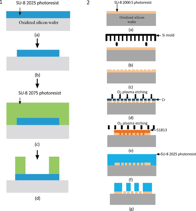
The method can also be used to encapsulate therapeutic molecules or cells that secrete therapeutic molecules. The system of encapsulation consists of a hollow cuboid base with a nanoporous lid bonded on top. Additional surface(s) may be made nanoporous as required. The process flows for both the lid and base are shown in Fig. (13) [41]. The nanoporosity in the lid was achieved using nanoimprint lithography, followed by oblique angle Cr deposition and plasma etching, as shown in Fig. (13). This is one of the few techniques which employs nanoimprint lithography and thus can have a much higher throughput than the previous methods.
Fig. (13).
Schematic (1) shows the process flow for the fabrication of the cuboid base and schematic (2) shows the process flow based on nanoimprint lithography for the fabrication of the nanoporous lid [41].
After the cuboid base and the nanoporous lids are fabricated, pancreatic islets, the microorgan systems that secrete insulin, can be loaded into the hollowed cuboid base for diabetes therapy application. Islets were pipette into the encapsulation space of the cuboid base and allowed to settle under gravity. The bases were then closed with the nanoporous lids and maintained in a tissue culture dish. Fig. (14) shows the SEM images of the fabricated cuboid base and the nanoporous lids, and also optical image of the sealed box loaded with islets, demonstrating the functionality of the nanoporous microcontainer.
Fig. (14).

EM images showing (a) the SU-8 hollowed cuboid base and (b) the nanoporous microcontainer lid; (c) encapsulated islet shows uptake of the molecular dye FM 4–64, suggesting adequate device porosity for the transport of nutrients, secretagogues, and hormones necessary for cell survival and function [41].
4). Reconfigurable Microstructures [37]
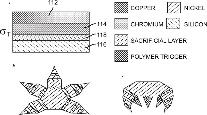
The previous invention by Gracias [35, 36] has one major problem: the temperature required for melting the solder was too high. Thus the concept used in this patent differs mainly in the fact that the fabrication is a low-temperature process. The folding of the faces is brought about by a Cu/Cr/polymer trilayer hinge material, as shown in Fig. (15).
Fig. (15).
(a–c) Schematic representation of microstructures with multiple joints and geometries to achieve the required folded configuration. (a) Shows the different layers that make up the actuation hinges [37].
The stress is developed in copper and chromium layers due to lattice mismatch. It was observed that the thickness of the Cr layer has a direct impact on the angle of folding, due to which thickness greater than 50nm was preferred for 90° folding. The polymer layer prevented the structure from folding prior to release from the substrate. Once released the solution containing these microstructures was heated above 40°C to cause softening of the polymer and subsequent folding. The concept of the bimetallic layer has been borrowed from the MEMS world wherein an intensive study has been conducted on their properties. Following this the inventors have also envisaged the structure and functioning of a micro gripper to hold cells using the same bilayer structure.
V. CURRENT AND FUTURE DEVELOPMENTS
As the technology to fabricate smaller structures has advanced, the applications of the same in the field of nanomedicine will continue to burgeon. In the particular field described in this article, researchers have developed many innovative methods and ideas of using “top down” lithographic methods that are developed first for semiconductor industry to make precisely controlled nanostructures and devices for medical applications. But for every new invention the key challenges that need to be met include bio-compatibility, reliability, manufacturing process for high throughput and large volumes, commercial viability, and low cost apart from the need for novelty and inventiveness over prior art. More importantly, research must be carried on to validate the positive impacts of these ideas and methods on specific medical applications. The future developments of these top-down lithography methods must address the above-mentioned challenges.
VI. CONCLUSION
In this article, recent inventions of various applications of semiconductor fabrication methods to nanomedicine areas are reviewed. In comparison to conventional chemistry methods, these “top down” lithographic methods provide better controllability and uniformity of nanostructures and nano-devices, which may further improve the performance of these nanostructures to be used in nanomedicine applications such as medical diagnostics and drug delivery. For example, nanochannels can stretch out DNA molecules from their coiled morphology to enable precise and high-speed DNA length/size measurements; shape specific and monodispersed nanoparticles made by nanoimprint lithography hold promise to improve drug delivery efficacy; and drug-delivery microcontainers with nanopores defined precisely by lithography can offer better protection to the cell or therapeutic agent from the immune system, etc. However, to fully unleash the potential of these emerging methodologies, extensive research needs to be performed to validate these ideas for specific nanomedicine applications.
Acknowledgments
This work is supported by the Department of the Army (W81XWH-BAA08) and Montcrief Foundation (W.H.), National Institutes of Health Grant (NIH R01 EB007456) and an Innovative Award from Juvenile Diabetes Research Foundation (B.G.).
Footnotes
CONFLICT OF INTEREST
BG is co-inventor on ref. [36].
References
- 1.Gates BD, Xu QB, Stewart M, Ryan D, Willson CG, Whitesides GM. New approaches to nanofabrication: Molding, printing, and other techniques. 2005;105(4):1171–96. doi: 10.1021/cr030076o. [DOI] [PubMed] [Google Scholar]
- 2.Saavedra HM, Mullen TJ, Zhang PP, Dewey DC, Claridge SA, Weiss PS. Hybrid strategies in nanolithography. Rep Prog Phys. 2010;73(3):40. [Google Scholar]
- 3.de Gennes PG. Scaling concepts in polymer physics. Cornell University Press; 1979. [Google Scholar]
- 4.Chou SY, Krauss PR, Renstrom PJ. Nanoimprint lithography. J Vac Sci Technol B. 1996;14(6):4129–33. [Google Scholar]
- 5.Brueck SRJ, Zaidi SH, Chen X, Zhang Z. Interferometric lithography - from periodic arrays to arbitrary patterns. Microelectron Eng. 1998;42:145–8. [Google Scholar]
- 6.Cao H, Tegenfeldt Jonas O, Chou Stephen, Austin Robert H. Gradient structures interfacing microfluidics and nanofluidics, methods for fabrication and uses thereof. 7217562. US. 2007
- 7.Jo K, Dhingra DM, Odijk T, et al. A single-molecule barcoding system using nanoslits for DNA analysis. Proc Natl Acad Sci U S A. 2007;104(8):2673–8. doi: 10.1073/pnas.0611151104. [DOI] [PMC free article] [PubMed] [Google Scholar]
- 8.Chou SY, Cao Han, Austin Robert H, Yu Zhaoning, Tegenfeldt Jonas O. Nanochannel arrays and their preparation and use for high throughput macromolecular analysis. 7670770. US. 2010
- 9.Tegenfeldt JO, Prinz C, Cao H, et al. The dynamics of genomic-length DNA molecules in 100-nm channels. Proc Natl Acad Sci U S A. 2004;101(30):10979–83. doi: 10.1073/pnas.0403849101. [DOI] [PMC free article] [PubMed] [Google Scholar]
- 10.Abbott NL, Skaife JJ. Method and apparatus for detection of microscopic pathogens. 20020028451. US. 2002
- 11.Dendukuri D, Tsoi K, Hatton TA, Doyle PS. Controlled synthesis of nonspherical microparticles using microfluidics. Langmuir. 2005;21(6):2113–6. doi: 10.1021/la047368k. [DOI] [PubMed] [Google Scholar]
- 12.Gref R, Minamitake Y, Peracchia MT, Trubetskoy V, Torchilin V, Langer R. Biodegradable Long-circulating polymeric nanospheres. Science. 1994;263(5153):1600–3. doi: 10.1126/science.8128245. [DOI] [PubMed] [Google Scholar]
- 13.Heurtault B, Saulnier P, Pech B, Proust JE, Benoit JP. Physico-chemical stability of colloidal lipid particles. Biomaterials. 2003;24(23):4283–300. doi: 10.1016/s0142-9612(03)00331-4. [DOI] [PubMed] [Google Scholar]
- 14.Park JH, von Maltzahn G, Zhang LL, et al. Systematic Surface Engineering of Magnetic Nanoworms for in vivo Tumor Targeting. Small. 2009;5(6):694–700. doi: 10.1002/smll.200801789. [DOI] [PMC free article] [PubMed] [Google Scholar]
- 15.Tao L, Hu W, Liu YL, Huang G, Sumer BD, Gao JM. Shape-specific polymeric nanomedicine: emerging opportunities and challenges. Exp Biol Med. 236(1):20–9. doi: 10.1258/ebm.2010.010243. [DOI] [PubMed] [Google Scholar]
- 16.Geng Y, Dalhaimer P, Cai SS, et al. Shape effects of filaments versus spherical particles in flow and drug delivery. Nat Nanotechnol. 2007;2(4):249–55. doi: 10.1038/nnano.2007.70. [DOI] [PMC free article] [PubMed] [Google Scholar]
- 17.Muro S, Garnacho C, Champion JA, et al. Control of endothelial targeting and intracellular delivery of therapeutic enzymes by modulating the size and shape of ICAM-1-targeted carriers. Mol Ther. 2008;16(8):1450–8. doi: 10.1038/mt.2008.127. [DOI] [PMC free article] [PubMed] [Google Scholar]
- 18.Nafea EH, Marson A, Poole-Warren LA, Martens PJ. Immunoisolating semi-permeable membranes for cell encapsulation: Focus on hydrogels. J Control Release. 154(2):110–22. doi: 10.1016/j.jconrel.2011.04.022. [DOI] [PubMed] [Google Scholar]
- 19.Ferrari MLCA. Therapeutic microdevices and methods of making and using same. 6107102. US. 2000
- 20.Hanahan D, Weinberg RA. The hallmarks of cancer. Cell. 2000;100(1):57–70. doi: 10.1016/s0092-8674(00)81683-9. [DOI] [PubMed] [Google Scholar]
- 21.Martin FJSF, CA, US), Ferrari, Mauro (DUBLIN, OH, US). Microfabricated particles and method for treating soild tumours. US20030114366, 2003.
- 22.Desai TA, Chu WH, Tu JK, Beattie GM, Hayek A, Ferrari M. Microfabricated immunoisolating biocapsules. Biotechnol Bioeng. 1998;57(1):118–20. doi: 10.1002/(sici)1097-0290(19980105)57:1<118::aid-bit14>3.0.co;2-g. [DOI] [PubMed] [Google Scholar]
- 23.Chang TMS. Semipermeable microcapsules. Science. 1964;146(364):524–5. doi: 10.1126/science.146.3643.524. [DOI] [PubMed] [Google Scholar]
- 24.Peppas NA. Hydrogels in medicine and pharmacy : vol.1 fundamentals. Boca Raton, Fla: CRC Press; 1986. [Google Scholar]
- 25.Kawata S, Sun HB, Tanaka T, Takada K. Finer features for functional microdevices - Micromachines can be created with higher resolution using two-photon absorption. Nature. 2001;412(6848):697–8. doi: 10.1038/35089130. [DOI] [PubMed] [Google Scholar]
- 26.Romankiw LT. A path: From electroplating through lithographic masks in electronics to LIGA in MEMS. Electrochim Acta. 1997;42(20–22):2985–3005. [Google Scholar]
- 27.Whitesides GM, Grzybowski B. Self-assembly at all scales. Science. 2002;295(5564):2418–21. doi: 10.1126/science.1070821. [DOI] [PubMed] [Google Scholar]
- 28.Syms RRA, Yeatman EM, Bright VM, Whitesides GM. Surface tension-powered self-assembly of micro structures - The state-of-the-art. J Microelectromech Syst. 2003;12(4):387–417. [Google Scholar]
- 29.Jager EWH, Smela E, Inganas O. Microfabricating conjugated polymer actuators. Science. 2000;290(5496):1540–5. doi: 10.1126/science.290.5496.1540. [DOI] [PubMed] [Google Scholar]
- 30.Suzuki K, Yamada H, Miura H, Takanobu H. Self-assembly of three dimensional micro mechanisms using thermal shrinkage of polyimide. Microsyst Technol. 2007;13(8–10):1047–53. [Google Scholar]
- 31.Luo JK, He JH, Fu YQ, et al. Fabrication and characterization of diamond-like carbon/Ni bimorph normally closed microcages. J Micromech Microeng. 2005;15(8):1406–13. [Google Scholar]
- 32.Arora WJ, Nichol AJ, Smith HI, Barbastathis G. Membrane folding to achieve three-dimensional nanostructures: Nanopatterned silicon nitride folded with stressed chromium hinges. Appl Phys Lett. 2006;88(5):3. [Google Scholar]
- 33.Smela E, Inganas O, Lundstrom I, Ohman O. Method for the manufacturing of micromachined structures and a micromachined structure manufactured using such method. 6103399. US. 2000
- 34.Smela E, Inganas O, Lundstram I. Controlled Folding of Micrometer-Size Structures. Science. 1995;268(5218):1735–8. doi: 10.1126/science.268.5218.1735. [DOI] [PubMed] [Google Scholar]
- 35.Gimi B, Leong T, Gu ZY, et al. Self-assembled three dimensional radio frequency (RF) shielded containers for cell encapsulation. Biomed Microdevices. 2005;7(4):341–5. doi: 10.1007/s10544-005-6076-9. [DOI] [PubMed] [Google Scholar]
- 36.Gracias DH, Gimi B, Bhujwalla ZM. Self-assembled, micropatterned, and radio frequency (RF) shielded biocontainers. /2007/014113. WO. 2007
- 37.Gracias DH, Leong TG-m. Reconfigurable lithographic structures. 20100326071. US. 2010
- 38.Leong T, Ye HK, Call E, et al. MEMS 2006: 19th IEEE International Conference on Micro Electro Mechanical Systems, Technical Digest. New York: IEEE; 2006. Microfabrication and self-assembly of 3D microboxes for biomedical applications; pp. 502–5. [Google Scholar]
- 39.Nemani K, Kwon J, Trivedi K, Hu W, Lee JB, Gimi B. Biofriendly bonding processes for nanoporous implantable SU-8 microcapsules for encapsulated cell therapy. J Microencapsul. 28(8):771–82. doi: 10.3109/02652048.2011.621552. [DOI] [PMC free article] [PubMed] [Google Scholar]
- 40.Gimi B, Kwon J, Kuznetsov A, et al. A nanoporous, transparent microcontainer for encapsulated islet therapy. J Diabetes Sci Technol. 2009;3(2):297–303. doi: 10.1901/jaba.2009.3-297. [DOI] [PMC free article] [PubMed] [Google Scholar]
- 41.Kwon J, Trivedi K, Krishnamurthy NV, Hu W, Lee JB, Gimi B. SU-8-based immunoisolative microcontainer with nanoslots defined by nanoimprint lithography. J Vac Sci Technol B. 2009;27(6):2795–800. doi: 10.1116/1.3258146. [DOI] [PMC free article] [PubMed] [Google Scholar]
- 42.Roy K, Shi L, Glangchai LC. Methods for fabricating nano and microparticles for drug delivery. 20070031505. US. 2006


