
FIGURE 4.
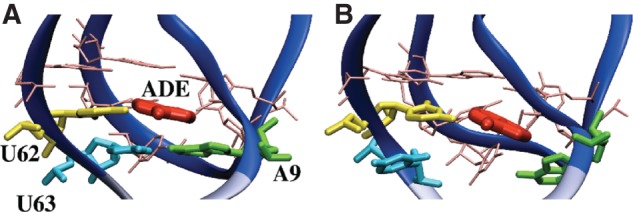
Representative structures of the Holo binding pocket at the beginning (RMSD = 0 nm) (A) and at the end (RMSD = 0.35 nm) (B) of the SMD. The portion of the P1 stem removed in our simulations is in light blue. Bases forming the binding pocket are labeled, ligand is shown in red. A9-U63 pair is formed in A and disrupted in B.