

Abstract
Objectives:
This study investigated the absorbed doses in a full anthropomorphic body phantom from two different panoramic radiography devices, performing protocols with and without applying a lead apron.
Methods:
A RANDO® full body phantom (Alderson Research Laboratories Inc., Stamford, CT) was equipped with 110 thermoluminescent dosemeters at 55 different sites and set up in two different panoramic radiography devices [SCANORA® three-dimensional (3D) (SOREDEX, Tuusula, Finland) and ProMax® 3D (Planmeca, Helsinki, Finland)] and exposed. Two different protocols were performed in the two devices. The first protocol was performed without any lead shielding, whereas the phantom was equipped with a standard adult lead apron for the second protocol.
Results:
A two-tailed paired samples t-test for the SCANORA 3D revealed that there is no difference between the protocol using lead apron shielding (m = 87.99, s = 102.98) and the protocol without shielding (m = 87.34, s = 107.49), t(54) = −0.313, p > 0.05. The same test for the ProMax 3D showed that there is also no difference between the protocol using shielding (m = 106.48, s = 117.38) and the protocol without shielding (m = 107.75, s = 114,36), t(54) = 0.938, p > 0.05.
Conclusions:
In conclusion, the results of this study showed no statistically significant differences between a panoramic radiography with or without the use of lead apron shielding.
Keywords: radiation protection; thermoluminescent dosimetry; radiography, panoramic; dentistry
Introduction
Widespread and easy to use, panoramic radiography (PR) is still the most important imaging modality in dentistry. It can provide an overview of the jaws, teeth and other tissues in the facial area, making it a popular method worldwide. Although the number of examinations performed is very high, the ratio of the effective dose to the population is very low. Collimation, filtration and more effective image receptors in digital PR devices are technical features that contribute to lowering the dose required to produce an image. According to the “as low as reasonably achievable” radiation protection principle, the decision to perform radiographs must be evaluated carefully for each patient. After all, “not doing the image” is the best radiation protection. In some countries, the use of lead aprons in dental radiography is popular for historic reasons, despite the questionable effect of the absorbed doses in the human body.
From the beginning, radiation protection research in dentistry was predominantly concentrated in this area. Thermoluminescent dosemeter (TLD)-based simulations and Monte Carlo simulations were performed to evaluate the effective dose received by a patient. PR devices were also developed further, improving image quality and dose-information efficiency.
As radiation protection is an important issue, there has been intense discussion about whether a lead apron is needed during a PR. A lead apron positioned on the patient's shoulder does not influence the primary X-ray beam. Furthermore, scattering generally occurs when the photons are already in the patient, mostly because of the Compton effect. In addition, most aprons do not protect the thyroid from radiation exposure. Previous studies have shown that lead apron shielding has only little relevance for the absorbed doses in a patient's torso.1 The European Academy of DentoMaxilloFacial Radiology supports these results with its recently published Radiation Protection No. 172 guideline.2 At the same time, however, there is only little supporting evidence.
The aim of this study was to evaluate possible differences in the absorbed doses in a human full-body phantom using PR (a) with and (b) without lead apron shielding.
Materials and methods
A RANDO® full body phantom (Alderson Research Laboratories Inc., Stamford, CT) was equipped with 110 TLDs at 55 different sites. After that, the phantom was set up in two different PR devices and exposed. Two different protocols were performed in the two devices. The first protocol was performed without any lead shielding, while the phantom was equipped with a standard adult lead apron (RD635E; MAVIG GmbH, Munich, Germany) for the second protocol. Subsequent to the exposures, the TLDs were read out and the values obtained were evaluated statistically. All of the exposures, as well as the read out process, took place in the Dental Diagnostic Center, Freiburg, Germany. In this way, it was possible to exclude many influencing factors like transportation, time or mailing of TLD, or at least assume them to the same for all of the protocols performed.
The phantom
A RANDO full body phantom was used to simulate the soft tissues and hard tissues of a human body. The phantom was constructed by using a natural human skeleton embedded in a material that corresponded to soft tissue with a physical density of 0.997 g cm−3.3 The phantom was sliced into 2.5 cm horizontal sections with drilled holes for TLD placement. The sections were numbered from 0 to 35 from head to hip. The fully compounded phantom simulated an average male patient with a height of 175 cm and a weight of 73.5 kg.
The thermoluminescent dosemeter
The absorbed doses were measured using 110 solid TLD-100H chips, 4.5 × 0.8 mm in size (Thermo Fisher Scientific, Waltham, MA). The measuring range of the TLD was between 1 µGy and 10 Gy with negligible fading. All the TLDs were calibrated using a defined exposure (Ddef) with 5.05 × 10⁵ μGy at 90 kV. After the readout process, the detected energy (Adet) was used to calculate a calibration factor (K):
 |
The calculated calibration factors of all available TLD were averaged to K = 3.73 × 10⁻² [n = 120; standard deviation (SD) = 6.87 × 10⁻⁴; SD% = 1.84)] TLD outside the range of twice the standard deviation were excluded and replaced. Tissues possibly affected by radiation exposure were selected. Table 1 shows the 55 sites of TLD placements in the phantom according to these tissues. Five additional TLD remained unexposed and were kept outside the influence of radiation from the devices to detect background radiation or other influencing factors.
Table 1.
Thermoluminescent dosemeter (TLD) distribution in the phantom
| Section | Tissue, area | TLD serial |
| 1 | Calvaria, left | 1 |
| 3 | Ethmoidal cells | 2 |
| Midbrain | 3 | |
| Lens, left | 51 | |
| Lens, right | 52 | |
| 4 | Pituitary gland | 4 |
| Orbital cavity, left | 5 | |
| Orbital cavity, right | 6 | |
| 5 | Cheek, right | 53 |
| Cheek, left | 54 | |
| 6 | Mandible, left | 7 |
| Mandible, right | 8 | |
| 7 | Submandibular gland, left | 9 |
| Neck, left | 10 | |
| Mouth base, central | 11 | |
| 8 | Oesophagus, cervical 4 | 12 |
| 9 | Thyroid, central | 13 |
| Thyroid, skin surface | 55 | |
| 10 | Trachea, cervical 7 | 14 |
| 11 | Lymph node, cervical 7 | 15 |
| 12 | Oesophagus, cervical 8 | 16 |
| 14 | Lung, left | 17 |
| Lung, right | 18 | |
| Heart, left | 19 | |
| Heart, right | 20 | |
| 15 | Breast, left | 21 |
| Breast, right | 22 | |
| 17 | Lymph node, thoracic 7 | 23 |
| 18 | Spleen, ventral | 24 |
| Spleen, dorsal | 25 | |
| 19 | Liver, ventral | 26 |
| Liver, dorsal | 27 | |
| Adrenal gland, left | 28 | |
| Adrenal gland, right | 29 | |
| 20 | Stomach, left | 30 |
| Stomach, right | 31 | |
| Kidney, left | 32 | |
| Kidney, right | 33 | |
| Gall bladder, left | 34 | |
| Gall bladder, right | 35 | |
| 21 | Colon, left flexure | 36 |
| Colon, right flexure | 37 | |
| Pancreas, left | 38 | |
| Pancreas, right | 39 | |
| 22 | Lymph node, lumbar 2 | 40 |
| 26 | Small intestine, left | 41 |
| Small intestine, right | 42 | |
| 29 | Ovaries, left | 43 |
| Ovaries, right | 44 | |
| 30 | Colon, left | 45 |
| Colon, right | 46 | |
| 32 | Bladder, ventral | 47 |
| Bladder, dorsa | 48 | |
| Uterus, left | 49 | |
| Uterus, right | 50 | |
| Reference: TLD | 56 | |
| 57 | ||
| 58 | ||
| 59 | ||
| 60 |
Panoramic radiography devices
Two different PR devices were used in this study to exclude device-dependent factors that influenced the dose distribution: the SCANORA® 3D (SOREDEX, Tuusula, Finland) and the ProMax® 3D (Planmeca, Helsinki, Finland). Table 2 shows the selected exposure parameters and the shielding used. 50 scans per protocol were performed and divided by the number of scans performed to stabilize the absorbed dose values that were measured. Figure 1 shows the phantom with the apron in one of the devices.
Table 2.
Performed protocols
| Protocol | Device | Mode | kV | mA | Time (s) | Shielding |
| 1 | ProMax® 3D (Planmeca Oy, Helsinki, Finland) | Panoramic mode | 68 | 13 | 19 | None |
| 2 | ProMax 3D (Planmeca Oy) | Panoramic mode | 68 | 13 | 19 | Apron |
| 3 | SCANORA® 3D (SOREDEX, Tuusula, Finland) | Panoramic mode | 73 | 8 | 15 | None |
| 4 | SCANORA 3D (SOREDEX) | Panoramic mode | 73 | 8 | 15 | Apron |
Figure 1.
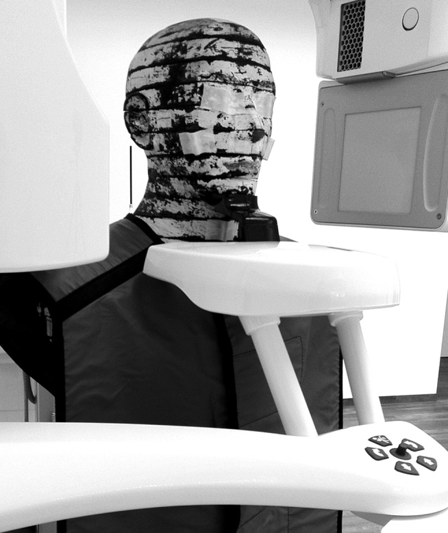
Phantom with apron set up in the device
Oven and reader
A microprocessor-controlled TLD oven (PTW, Freiburg, Germany) was used to reset and anneal all the TLDs at the same time and in a reproducible procedure. Prior to exposure, all the TLDs were heated to 400 °C and cooled down to 100 °C for 1 h.
After the exposure, they were cooled down to room temperature. The whole procedure took about 5 h. The readout process was performed in a Fimel LTMWin oven (Fimel, Fontenay-aux-Roses, France) with a standard planchet that enables measurements of TLD with 5 mm or less. Each TLD was placed in the oven, and the readout process under nitrogen atmosphere was initialized. The result of the process (digits) was displayed and exported to a .txt file. These digits multiplied by the calibration factor K yielded the absorbed doses for each TLD. The values of the two TLD at each site were averaged, the detected background radiation was subtracted and then divided by the number of the scans performed.
Results
As shown in Tables 3 and 4, no statistically significant difference was found between the two protocols in the two devices evaluated. A two-tailed paired samples t-test for the SCANORA 3D revealed that there is no difference between the protocol using shielding (mean = 87.99, STDV = 102.98) and the protocol without shielding (mean = 87.34, SD = 107.49), t(54) = −0.313, p > 0.05. The same test for the ProMax 3D likewise showed no difference between the protocol using shielding (mean = 106.48, SD = 117.38) and the protocol without shielding (mean = 107.75, SD = 114.36), t(54) = 0.938, p > 0.05. Another two-tailed paired samples t-test also yielded no difference between the two TLDs at each site (p > 0.05).
Table 3.
Absorbed doses for the SCANORA® 3D (SOREDEX, Tuusula, Finland)
| Thermoluminescent dosemeter serial | SCANORA 3D with | SCANORA 3D without | Δ (%) |
| 1 | 130.6 | 140.1 | 7.3 |
| 2 | 118.1 | 114.2 | −3.3 |
| 3 | 56.5 | 62.9 | 11.3 |
| 4 | 77.1 | 55.8 | −27.6 |
| 5 | 47.6 | 84.3 | 77.1 |
| 6 | 107.0 | 106.1 | −0.8 |
| 7 | 247.7 | 273.9 | 10.6 |
| 8 | 247.8 | 266.0 | 7.3 |
| 9 | 59.2 | 54.2 | −8.4 |
| 10 | 59.6 | 80.8 | 35.6 |
| 11 | 382.3 | 387.8 | 1.4 |
| 12 | 368.4 | 362.9 | −1.5 |
| 13 | 449.3 | 472.2 | 5.1 |
| 14 | 220.4 | 210.2 | −4.6 |
| 15 | 420.1 | 425.6 | 1.3 |
| 16 | 93.1 | 111.2 | 19.4 |
| 17 | 93.6 | 85.9 | −8.2 |
| 18 | 65.2 | 75.7 | 16.1 |
| 19 | 40.1 | 32.8 | −18.2 |
| 20 | 29.2 | 43.2 | 47.9 |
| 21 | 5.1 | 2.3 | −54.9 |
| 22 | 36.6 | 27.4 | −25.1 |
| 23 | 45.7 | 25.9 | −43.3 |
| 24 | 8.6 | 10.3 | 19.8 |
| 25 | 8.7 | 14.0 | 60.9 |
| 26 | 72.7 | 50.9 | −30.0 |
| 27 | 9.7 | 14.0 | 44.3 |
| 28 | 33.3 | 11.2 | −66.4 |
| 29 | 57.0 | 32.9 | −42.3 |
| 30 | 27.6 | 14.9 | −46.0 |
| 31 | 29.3 | 8.6 | −70.6 |
| 32 | 34.0 | 25.6 | −24.7 |
| 33 | 34.3 | 41.6 | 21.3 |
| 34 | 39.5 | 47.1 | 19.2 |
| 35 | 62.1 | 39.2 | −36.9 |
| 36 | 79.7 | 81.6 | 2.4 |
| 37 | 42.7 | 29.9 | −30.0 |
| 38 | 23.4 | 31.0 | 32.5 |
| 39 | 26.5 | 20.9 | −21.1 |
| 40 | 56.5 | 54.8 | −3.0 |
| 41 | 73.3 | 80.9 | 10.4 |
| 42 | 85.4 | 82.6 | −3.3 |
| 43 | 48.5 | 80.8 | 66.6 |
| 44 | 54.8 | 68.4 | 24.8 |
| 45 | 70.3 | 27.3 | −61.2 |
| 46 | 25.9 | 29.2 | 12.7 |
| 47 | 58.3 | 37.7 | −35.3 |
| 48 | 51.3 | 46.4 | −9.6 |
| 49 | 53.8 | 39.0 | −27.5 |
| 50 | 35.9 | 31.8 | −11.4 |
| 51 | 37.4 | 28.2 | −24.6 |
| 52 | 22.0 | 26.0 | 18.2 |
| 53 | 49.8 | 44.3 | −11.0 |
| 54 | 52.4 | 68.7 | 31.1 |
| 55 | 74.4 | 82.4 | 10.8 |
| Mean | −2.5 | ||
| SD | 32.2 |
SD, standard deviation.
Table 4.
Absorbed doses for the ProMax® 3D (Planmeca Oy, Helsinki, Finland)
| Thermoluminescent dosimeter serial | ProMax 3D with | ProMax 3D without | Δ [%] |
| 1 | 241.1 | 244.1 | 1.2 |
| 2 | 117.4 | 121.1 | 3.2 |
| 3 | 189.2 | 187.0 | −1.2 |
| 4 | 147.9 | 150.6 | 1.8 |
| 5 | 142.9 | 147.9 | 3.5 |
| 6 | 53.9 | 52.7 | −2.2 |
| 7 | 332.8 | 319.0 | −4.1 |
| 8 | 312.2 | 310.6 | −0.5 |
| 9 | 83.8 | 82.9 | −1.1 |
| 10 | 64.9 | 73.8 | 13.7 |
| 11 | 380.7 | 372.1 | −2.3 |
| 12 | 363.9 | 350.7 | −3.6 |
| 13 | 450.5 | 439.8 | −2.4 |
| 14 | 291.8 | 282.8 | −3.1 |
| 15 | 411.0 | 412.4 | 0.3 |
| 16 | 311.2 | 311.1 | −0.0 |
| 17 | 198.6 | 204.4 | 2.9 |
| 18 | 65.5 | 76.5 | 16.8 |
| 19 | 48.0 | 43.7 | −9.0 |
| 20 | 75.8 | 98.1 | 29.4 |
| 21 | 92.8 | 84.1 | −9.4 |
| 22 | 3.8 | 7.1 | 86.8 |
| 23 | 71.2 | 56.6 | −20.5 |
| 24 | 4.2 | 10.0 | 138.1 |
| 25 | 6.9 | 11.7 | 69.6 |
| 26 | 69.7 | 96.4 | 38.3 |
| 27 | 13.2 | 8.9 | −32.6 |
| 28 | 6.6 | 8.0 | 21.2 |
| 29 | 86.2 | 89.4 | 3.7 |
| 30 | 5.3 | 15.0 | 183.0 |
| 31 | 13.2 | 19.4 | 47.0 |
| 32 | 94.9 | 80.8 | −14.9 |
| 33 | 81.0 | 76.2 | −5.9 |
| 34 | 95.3 | 95.2 | −0.1 |
| 35 | 98.5 | 94.1 | −4.5 |
| 36 | 73.7 | 75.2 | 2.0 |
| 37 | 45.8 | 47.6 | 3.9 |
| 38 | 31.0 | 52.2 | 68.4 |
| 39 | 45.5 | 40.2 | −11.6 |
| 40 | 12.8 | 13.0 | 1.6 |
| 41 | 50.4 | 69.1 | 37.1 |
| 42 | 7.8 | 4.6 | −41.0 |
| 43 | 81.2 | 68.3 | −15.9 |
| 44 | 78.2 | 83.9 | 7.3 |
| 45 | 13.8 | 11.0 | −20.3 |
| 46 | 6.4 | 7.9 | 23.4 |
| 47 | 79.9 | 61.9 | −22.5 |
| 48 | 57.0 | 81.1 | 42.3 |
| 49 | 17.3 | 19.8 | 14.5 |
| 50 | 85.4 | 75.6 | −11.5 |
| 51 | 8.6 | 10.7 | 24.4 |
| 52 | 6.1 | 5.2 | −14.8 |
| 53 | 5.2 | 10.7 | 105.8 |
| 54 | 59.2 | 67.9 | 14.7 |
| 55 | 65.3 | 86.3 | 32.2 |
| Mean | 14.2 | ||
| SD | 40.0 |
SD, standard deviation.
Discussion
TLD-based measurements for evaluating the doses absorbed in a patient during an X-ray examination have been performed and described in prior published research.4–22 These TLD-based measurements are generally assumed to be accurate in an exactable range, so that they were appropriate for the present research.
The study investigated the doses absorbed in a full anthropomorphic body phantom using two different PR devices, and protocols were performed with and without the use of a lead apron. It was proven that examination protocols using a lead apron did not differ from those without an apron.
The wide ranges of temperature during the annealing and readout process and handling may cause damage to the TLD. The TLDs were checked carefully after each heating process and replaced in the event of possible damage to prevent incorrect values in the readout process.
Lead apron shielding in dental imaging is a subject of controversy, which has been discussed intensively. It is interesting to note that there is no overall agreement on this issue in different countries and that only very little research has been performed in the field of radiation protection by lead apron shielding. The findings of this study support the European Academy of DentoMaxilloFacial Radiology guidelines, which emphasize that there is no evidence supporting the routine use of lead apron shielding.
In earlier research, it was shown that TLD-based measurements are reasonable and accurate in the required range. Furthermore, TLDs are simple to use, equivalent to tissue and small in size.23 However, there are some limitations, which should be mentioned: transport times, temperature, air pressure, light and other factors that may influence the outcome of the measurement. Therefore, all the protocols and readouts were performed at one location. This made it possible to achieve constant conditions for all the measurements.
Three TLDs broke during the annealing process and had to be replaced by other calibrated TLDs.
TLD-based dose measurements are time consuming. Therefore, future research should investigate alternatives for calculating the doses received by a patient by other dental X-ray examinations.
In conclusion, the results of this study showed no statistically significant differences between a PR with or without the use of lead apron shielding. As predicted in a review article written by Horner1 in 1994, abdomen lead shielding has only very little influence, if any, on the doses absorbed during a dental PR.
References
- 1.Horner K. Review article: radiation protection in dental radiology. Br J Radiol 1994; 67: 1041–1049 [DOI] [PubMed] [Google Scholar]
- 2.European Commission Radiation Protection no. 172. Cone beam CT for dental and maxillofacial radiology. Evidence-based guidelines. Luxembourg: EC; 2012. Available from: ec.europa.eu/energy/nuclear/radiation_protection/doc/publication/172.pdf [Google Scholar]
- 3.Alderson SW, Lanzl LH, Rollins M, Spira J. An instrumented phantom system for analog computation of treatment plans. Am J Roentgenol Radium Ther Nucl Med 1962; 87: 185–195 [PubMed] [Google Scholar]
- 4.Bourgeois M, Wood RE, Pharoah MJ. Reducing transmitted radiation in dental radiography. Health Phys 1992; 62: 546–552 [DOI] [PubMed] [Google Scholar]
- 5.Soh G, Chong YH. Variability of two methods of measuring absorbed dose in dental radiography. Clin Prev Dent 1992; 14: 17–19 [PubMed] [Google Scholar]
- 6.Goldstein A. Exposure and dose in panoramic radiology. Med Phys 1998; 25: 1033–1040 [DOI] [PubMed] [Google Scholar]
- 7.Aragno D, Fattibene P, Onori S. Dental radiography: tooth enamel EPR dose assessment from Rando phantom measurements. Phys Med Biol 2000; 45: 2671–2683 [DOI] [PubMed] [Google Scholar]
- 8.Dula K, Mini R, van der Stelt PF, Sanderink GC, Schneeberger P, Buser D. Comparative dose measurements by spiral tomography for preimplant diagnosis: the Scanora machine versus the Cranex Tome radiography unit. Oral Surg Oral Med Oral Pathol Oral Radiol Endod 2001; 91: 735–742 10.1067/moe.2001.113591 [DOI] [PubMed] [Google Scholar]
- 9.Lecomber AR, Yoneyama Y, Lovelock DJ, Hosoi T, Adams AM. Comparison of patient dose from imaging protocols for dental implant planning using conventional radiography and computed tomography. Dentomaxillofac Radiol 2001; 30: 255–259 10.1038/sj/dmfr/4600627 [DOI] [PubMed] [Google Scholar]
- 10.Ogundaret FO, Oni OM, Balogun FA. Measurements of X ray absorbed doses to dental patients in two dental X ray units in Nigeria. Radiat Prot Dosimetry 2002; 102: 355–358 [DOI] [PubMed] [Google Scholar]
- 11.Buch B, Fensham R. Orthodontic radiographic procedures-how safe are they? SADJ 2003; 58: 6–10 [PubMed] [Google Scholar]
- 12.Schulze D, Heiland M, Thurmann H, Adam G. Radiation exposure during midfacial imaging using 4- and 16-slice computed tomography, cone beam computed tomography systems and conventional radiography. Dentomaxillofac Radiol 2004; 33: 83–86 [DOI] [PubMed] [Google Scholar]
- 13.Svenson B, Sjoholm B, Jonsson B. Reduction of absorbed doses to the thyroid gland in orthodontic treatment planning by reducing the area of irradiation. Swed Dent J 2004; 28: 137–147 [PubMed] [Google Scholar]
- 14.Gijbels F, Jacobs R, Bogaerts R, Debaveye D, Verlinden S, Sanderink G. Dosimetry of digital panoramic imaging. Part I: Patient exposure. Dentomaxillofac Radiol 2005; 34: 145–149 [DOI] [PubMed] [Google Scholar]
- 15.Dirican B, Ozen J, Beyzadeoglu M, Oysul K, Surenkok S, Sipahi C. In vitro evaluation of head and neck radiation shields used to reduce exit dose. Int J Prosthodont 2006; 19: 462–466 [PubMed] [Google Scholar]
- 16.Coppenrath E, Draenert F, Lechel U, Veit R, Meindl T, Reiser M, et al. Cross-sectional imaging in dentomaxillofacial diagnostics: dose comparison of dental MSCT and NewTom 9000 DVT. [Article in German]. Rofo 2008; 180: 396–401 10.1055/s-2008-1027142 [DOI] [PubMed] [Google Scholar]
- 17.Garcia Silva MA, Wolf U, Heinicke F, Grundler K, Visser H, Hirsch E. Effective dosages for recording Veraviewepocs dental panoramic images: analog film, digital, and panoramic scout for CBCT. Oral Surg Oral Med Oral Pathol Oral Radiol Endod 2008; 106: 571–577 10.1016/j.tripleo.2008.03.031 [DOI] [PubMed] [Google Scholar]
- 18.Palomo JM, Rao PS, Hans MG. Influence of CBCT exposure conditions on radiation dose. Oral Surg Oral Med Oral Pathol Oral Radiol Endod 2008; 105: 773–782 10.1016/j.tripleo.2007.12.019 [DOI] [PubMed] [Google Scholar]
- 19.Gavala S, Donta C, Tsiklakis K, Boziari A, Kamenopoulou V, Stamatakis HC. Radiation dose reduction in direct digital panoramic radiography. Eur J Radiol 2009; 71: 42–48 10.1016/j.ejrad.2008.03.018 [DOI] [PubMed] [Google Scholar]
- 20.Suomalainen A, Kiljunen T, Kaser Y, Peltola J, Kortesniemi M. Dosimetry and image quality of four dental cone beam computed tomography scanners compared with multislice computed tomography scanners. Dentomaxillofac Radiol 2009; 38: 367–378 10.1259/dmfr/15779208 [DOI] [PubMed] [Google Scholar]
- 21.Pauwels R, Beinsberger J, Collaert B, Theodorakou C, Rogers J, Walker A, et al. Effective dose range for dental cone beam computed tomography scanners. Eur J Radiol 2012; 81: 267–271 10.1016/j.ejrad.2010.11.028 [DOI] [PubMed] [Google Scholar]
- 22.Zenobio EG, Zenobio MA, Nogueira MS, Silva TA, Shibli JA. Absorbed radiation doses during tomographic examinations in dental implant planning: a study in humans. Clin Implant Dent Relat Res 2012; 14: 366–372 10.1111/j.1708-8208.2010.00277.x [DOI] [PubMed] [Google Scholar]
- 23.Rivera T. Thermoluminescence in medical dosimetry. Appl Radiat Isot 2012; 71 Suppl: 30–34 10.1016/j.apradiso.2012.04.018 [DOI] [PubMed] [Google Scholar]