Abstract
This study compared the effectiveness of the multifocal visual evoked cortical potentials (mfVEP) elicited by pattern pulse stimulation with that of pattern reversal in producing reliable responses (signal-to-noise ratio >1.359). Participants were 14 healthy subjects. Visual stimulation was obtained using a 60-sector dartboard display consisting of 6 concentric rings presented in either pulse or reversal mode. Each sector, consisting of 16 checks at 99% Michelson contrast and 80 cd/m2 mean luminance, was controlled by a binary m-sequence in the time domain. The signal-to-noise ratio was generally larger in the pattern reversal than in the pattern pulse mode. The number of reliable responses was similar in the central sectors for the two stimulation modes. At the periphery, pattern reversal showed a larger number of reliable responses. Pattern pulse stimuli performed similarly to pattern reversal stimuli to generate reliable waveforms in R1 and R2. The advantage of using both protocols to study mfVEP responses is their complementarity: in some patients, reliable waveforms in specific sectors may be obtained with only one of the two methods. The joint analysis of pattern reversal and pattern pulse stimuli increased the rate of reliability for central sectors by 7.14% in R1, 5.35% in R2, 4.76% in R3, 3.57% in R4, 2.97% in R5, and 1.78% in R6. From R1 to R4 the reliability to generate mfVEPs was above 70% when using both protocols. Thus, for a very high reliability and thorough examination of visual performance, it is recommended to use both stimulation protocols.
Keywords: Multifocal visual evoked cortical potential, Contrast vision, Spatial vision, Signal-to-noise analysis, Visual electrophysiology
Introduction
The multifocal visual evoked cortical potential (mfVEP) recording technique was developed by Erich Sutter as a method to investigate the cortical activity evoked by simultaneous stimulation of multiple areas of the visual field (1). This method has been used in several basic and clinical applications (2-12). Elicited responses arise from a stimulation protocol based on changes in the spatial information of the stimuli. Pattern reversal configuration was initially proposed and it is still the most used presentation mode among mfVEP studies (1,3,13,14).
Different stimulus configurations such as pattern pulse or pattern onset-offset have been used as alternative methods to investigate visual cortical physiology (11,12,15-19). The presentation modes differ from each other in the stimulus configurations that have been shown for each element of the m-sequence. Binary (succession of 0 and 1 states) and tertiary (succession of 0, 1, and -1 states) m-sequences have been used to set the presentation modes. Usually, pattern reversal is set by binary sequences, each m-sequence state represented by two phase-inverted patterns. Pattern onset was introduced by Hoffmann et al. (18). For this, one m-sequence state was represented by a pattern presentation during a frame period followed by a mean luminance homogeneous field during one more frame period, and another m-sequence state was represented by two frame periods of homogeneous field. The recording time spent during pattern onset stimulation was two times longer than the time spent using pattern reversal mode. Pattern offset mode is the opposite configuration of pattern onset mode. It is represented by one m-sequence state triggering a short period of homogeneous field followed by a longer pattern presentation and one m-sequence state triggering only pattern presentation. Pattern offset mode was used by Fortune et al. (16). Pattern pulse was introduced by James (11) and was set to show a pattern that lasted one frame period followed by a mean luminance homogeneous field. The pattern was presented randomly at an interval between 0.4 and 0.6 s.
Due to the clinical importance of this method, several studies have compared the signal-to-noise ratio (SNR) of pattern reversal mfVEP to those elicited by other stimulus configurations, since the former was not able to generate measurable responses from all stimulated areas (16-18,20). Fortune et al. (16) compared the multifocal responses elicited by pattern reversal, pattern onset, pattern offset, and sparse pulse stimuli. They found similar waveforms for pattern reversal and pattern onset mfVEP. Pattern onset and sparse pattern pulse mfVEPs were 3.5 times larger than pattern reversal mfVEPs. Pattern offset mfVEP had a different waveform compared to those elicited by other mode presentations, and was two times smaller than pattern onset. Hoffmann et al. (18) compared the SNR of mfVEPs elicited by pattern reversal and pattern onset. The pattern onset recording duration was twice as long as pattern reversal. Hoffmann et al. (18) found that pattern onset enhanced the amplitude by 30% in the central areas, but it elicited a 30% lower response in the periphery field. The combination of both tests reduced the number of falsepositive scotomas to less than 1.5% of the location. Gerth et al. (17) studied the topography of pattern reversal and pattern onset chromatic mfVEPs. Instead of using a dartboard for stimulation, they used a stimulation consisting of hexagons filled with triangles in order to reduce high spatial frequency components in the central area of the stimulus. For both stimuli, they found larger responses in the central field and depressed amplitude in the peripheral field. Pattern onset chromatic mfVEPs were larger than those elicited by pattern reversal. Maddess et al. (20) studied the contrast response function of pattern reversal mfVEPs to three configurations of temporally sparse stimuli. They found that SNR at 40% contrast were similar among the presentation modes, but the sparse mfVEP amplitudes grew faster as the contrast increased than pattern reversal mfVEPs. Maddess et al. (20) suggested that the contrast dependence of the mfVEP amplitude was due to possible influences of retinal contrast gain control, or intracortical and cortical-geniculate feedback.
The main explanation for false-negative waveforms in mfVEP tests lies in the cortical convolutions resulting in failure of the dipoles to project onto a specific derivation or in the cancellation of opposing dipoles (21). However, it is possible that different contrast gain mechanisms may be the cause of the lack of responses in some sectors (13).
We compared the SNR of mfVEPs elicited by pattern reversal and a pattern pulse protocol. In the present study, we used a pattern pulse presentation mode in which one msequence state showed a pattern and another m-sequence state showed a homogeneous field. Both m-sequence states lasted one frame period, matching the recording duration for pattern reversal mode, which was also composed by one frame period for each m-sequence state. We evaluated the performance of the different sectors to generate reliable responses for both stimulation protocols. Our goal was to identify how to elicit reliable waveforms by pattern reversal and pattern pulse presentation modes, which could be compared in a straightforward manner. Although pattern reversal is the most used protocol in clinical trials, it has some limitations and it is important to investigate different alternatives to analyze visual function integrity.
Material and Methods
Subjects
Fourteen healthy subjects (27 ± 5.4 years old) with best corrected visual acuity equal to 20/20 or better and no ophthalmologic diseases participated in this study. Monocular stimulation was used for all subjects. The study was approved by the Ethics Committee of the Núcleo de Medicina Tropical, Universidade Federal do Pará, and all subjects gave written informed consent to participate.
Stimuli
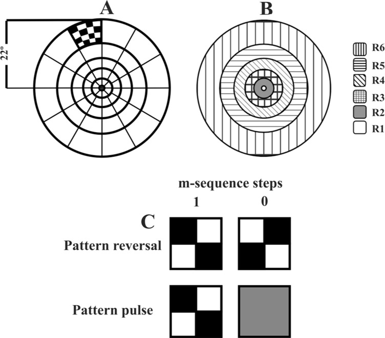
A 20″ color CRT monitor (75 Hz, 1280 × 1024 pixels, Eizo, Japan) was driven by the Veris Science v6.10 system (Electrodiagnostic Imaging - EDI, USA) to display a 60-sector dartboard (radius: 22° of visual angle; Figure 1). Each sector consisted of 16 squares (8 white and 8 black) with high luminance Michelson contrast (99%) and 80 cd/m2 mean luminance. Each sector was controlled by a binary m-sequence in the time domain. Two stimulation protocols were used: pattern reversal and pattern pulse. For the pattern reversal mode, one m-step showed a chessboard pattern during one frame period and another m-step showed the same chessboard pattern 180° spatial phase reversed (Figure 1C) during one frame period. For pattern pulse, one m-step showed a chessboard pattern during one frame period and the other m-step showed a mean luminance homogeneous field (Figure 1B) during one frame period. Both protocols spent the same recording time.
Figure 1. Sixty sector dartboard consisting of 6 concentric rings (A). Pattern reversal and pattern pulse modes drove the presentation in each sector modulated by a binary m-sequence. Rings of same eccentricity (B). R1 is the inner ring and R6 is the outer ring. Pattern reversal mode: m-step 1 showed a chessboard pattern during a frame interval, m-step -1 showed the reversed chessboard pattern during a frame interval (C). Pattern pulse mode: m-step 1 showed a chessboard pattern during a frame interval, m-step -1 showed a zero contrast field during a frame interval (C).
Electrode placement and recording settings
Four consecutive recording trials were performed (two pattern reversal and two pattern pulse trials). Three active gold-cup electrodes were placed 4 cm above the inion (channel 1), 1 cm above the inion, and 4 cm to the right (channel 2) and left (channel 3), respectively (10). Another gold-cup electrode, placed in the inion, was the reference for the three active electrodes. The ground electrode was placed on the forehead. The recordings were amplified 100,000 times (Grass, USA), digitized at 1200 Hz and on-line band-pass filtered at 3-100 Hz. Additionally, the recordings were digitally filtered off-line by the VERIS system at 0-30 Hz. No artifact rejection or spatial smoothing was applied to the data.
Analysis settings: signal-to-noise ratio measurements
The recorded information of three physical derivations (channels 1, 2, 3) was exported from the Veris system to be analyzed in Matlab R2010b (Mathworks, USA). Three additional channels were obtained by subtraction of the physical channels (channels 4, 5, 6). The first slice of the second-order kernel for pattern reversal and the first-order kernel for pattern pulse were extracted for analysis. We performed an SNR evaluation similar to the one described by Zhang et al. (22), in which the waveforms of two trials from each presentation mode session were averaged. The SNR definition initially given by Zhang and Hood (23) deviates from the conventional SNR definition. Then, the SNR of each waveform was calculated as: SNR = [RMS(40-150 ms) / mean RMS(325-430 ms)] - 1, where RMS(40-150 ms) is the RMS amplitude of the waveform in the interval of 40 to 150 ms. The mean RMS(325-430 ms) is the average RMS amplitude of all 60 waveforms in the interval of 325 to 430 ms. We found a combination of waveforms with best SNR among six channels for each sector (best channel) to be used in the comparisons.
Analysis settings: testing the waveforms reliability
To determine if each waveform would be a reliable response, we applied an approach of false-positive rates obtained from the cumulative distribution of SNRs from the noise interval of the waveforms as described by Zhang et al. (22): SNR = [RMS(325-430 ms) / meanRMS(325-430 ms)] - 1, where RMS(325-430 ms) is the RMS amplitude of the waveform in the interval of 325 to 430 ms. After the false-positive rate approach, we found that for the entire data sample the SNRs above 1.359 would correspond to a probability of 5% of being part of the noise distribution. We considered as reliable waveforms those with an SNR above 1.359.
Statistical analysis
We used one-way ANOVA with Bonferroni's correction (α = 0.05) to compare the SNR from reliable data and rate of reliable waveforms elicited by both stimulus protocols. Our analysis considered waveforms included in six concentric rings of the visual field (R1 is the inner ring, R6 is the outer ring, and R2-R5 are intermediate rings from R1 to R6; Figure 1).
Results
Waveforms and SNR analysis
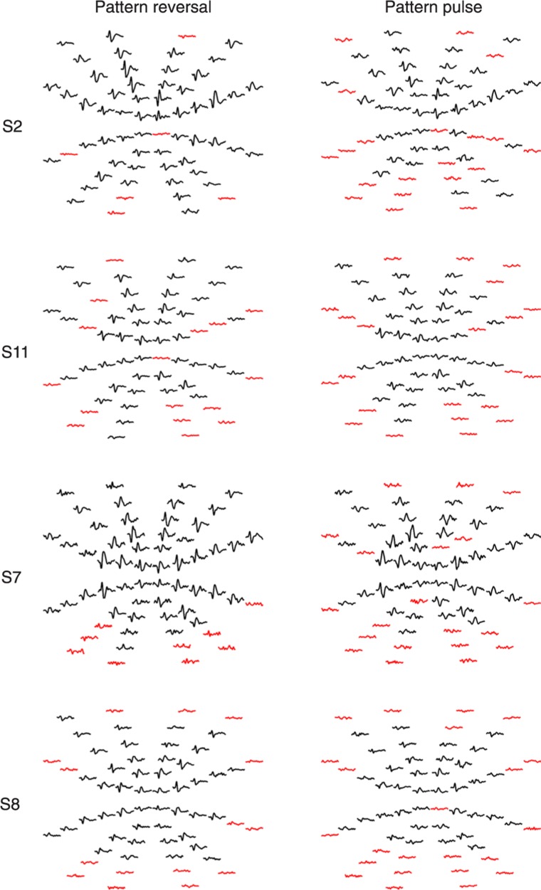
The entire analysis was conducted across subjects. Figure 2 shows the best channel response elicited by pattern reversal and pattern pulse from four subjects. Reliable waveforms (SNR >1.359) are marked in black and the waveforms that indicate absence of signal (SNR <1.359) are marked in red.
Figure 2. Multifocal visual evoked potential arrays elicited by pattern reversal and pattern pulse presentation mode from four subjects. Reliable waveforms are marked in black, while red waveforms indicate false-positive waveforms.
In the comparison of all reliable waveforms, statistical analysis showed significantly (P < 0.05) higher SNR for pattern reversal mfVEP (SNR = 4.025 ± 2.3) compared to pattern pulse mfVEP (SNR = 2.21 ± 1.7). For the R1, R2, R3, and R6 rings, there were no significant differences in the SNR of reliable waveforms between the two protocols. For the R4 and R5 rings there were significant differences favoring the SNR of pattern reversal mfVEP (P < 0.05).
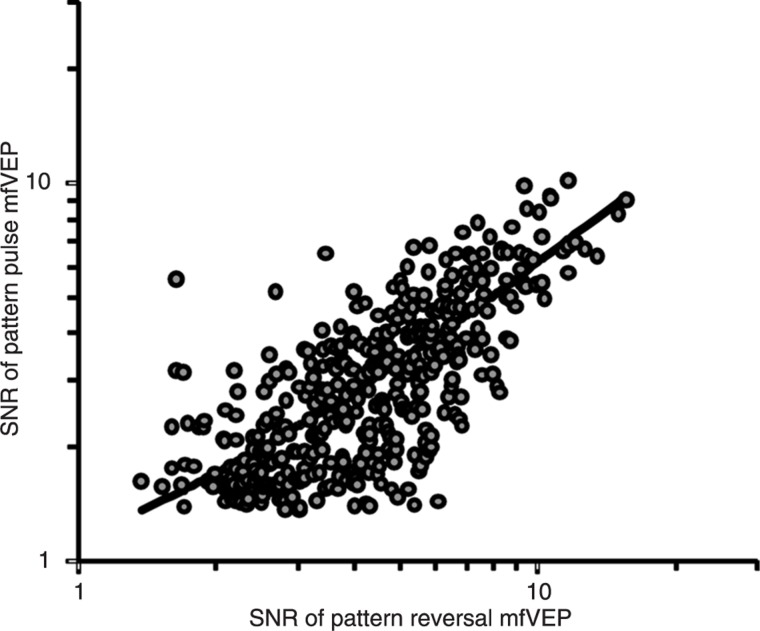
A comparison of the SNRs of reliable waveforms elicited from the same sector for both protocols showed a correlation coefficient (R) equal to 0.77, which showed that the SNR of reliable waveforms elicited by both presentation modes varied simultaneously, obeying a linear relationship (Figure 3).
Figure 3. Correlation between signal-to-noise ratios (SNRs) of reliable waveforms elicited by pattern reversal and pattern pulse modes. The correlation coefficient was 0.77. SNR values of pattern reversal multifocal visual evoked potentials (mfVEPs) were higher than pattern pulse mfVEPs. The linear function (black line) that described the correlation was y = 0.56 × log10(x) + 0.59.
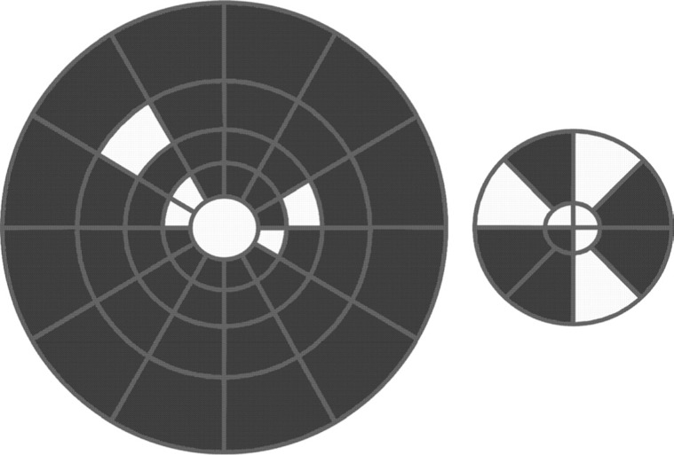
The pattern pulse mode showed the same or a better performance in generating reliable waveforms than the pattern reversal mode in three of four sectors (75%) in R1, three of eight sectors (37.3%) in R2, three of twelve sectors (25%) in R3, and one of twelve sectors in R4 and R5 (8.3%). Pattern pulse performance was worse than pattern reversal mode to generate reliable waveforms at all sectors in R6. We found that the performance of each sector generated reliable waveforms for both presentation modes. We observed that the pattern pulse mode showed the same or higher performance than the pattern reversal mode in eleven sectors. Figure 4 shows in white the sectors that after pattern pulse stimulation showed the same or higher performance than pattern reversal. Contrast adaptation and different neural generators could partially contribute to the better performance of pattern pulse, mainly in the central field.
Figure 4. Comparison of the performance of pattern pulse and pattern reversal by sector. The sectors in which the pattern pulse had the same or better performance than pattern reversal are in white. The analysis was conducted across subjects. The larger diagram represents rings R6, R5, R4, and R3 from periphery to center, while the smaller diagram represents rings R2 and R1 from periphery to center.
Reliability rate
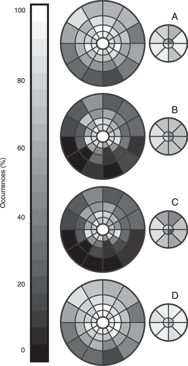
Table 1 shows the rate of reliable responses elicited from both stimulation protocols for all subjects. Figure 5 shows reliable waveforms in each sector for the pattern reversal mode (Figure 5A) and pattern pulse mode (Figure 5B). Figure 5C and D show the rate of reliable waveforms when a same sector elicited reliable waveform simultaneously for both protocols or in any protocol, respectively.
Table 1. Rates of reliable waveforms elicited by each ring in the visual field.
| Rate of reliable waveforms (%) | ||||||||||||||
|---|---|---|---|---|---|---|---|---|---|---|---|---|---|---|
| All rings | R1 | R2 | R3 | R4 | R5 | R6 | ||||||||
| PR | PP | PR | PP | PR | PP | PR | PP | PR | PP | PR | PP | PR | PP | |
| Average | 71.6* | 52.1 | 66 | 66 | 83.9 | 75 | 86.3 | 79.1 | 83* | 61.9 | 64* | 31.5 | 46.4* | 16 |
| Sterr | 3.7 | 4.5 | 8.5 | 10 | 4.4 | 6 | 3.1 | 6.5 | 3.8 | 5.8 | 5.8 | 5.5 | 6.5 | 4.6 |
Sterr = standard error; PR = pattern reversal; PP = pattern pulse.
P < 0.05 PR compared to PP (one-way ANOVA).
Figure 5. Rate of reliable waveforms. A, Pattern reversal. B, Pattern pulse. C, Rate considering reliable responses for both protocols (Logic AND). D, Rate considering reliable responses for one of the protocols (Logic OR). The rings are shown in two diagrams, a larger one and a smaller one. The larger diagram represents rings R6, R5, R4, and R3 from periphery to center, while the smaller diagram represents rings R2 and R1 from periphery to center.
In the analysis of all sectors, there was a higher rate of pattern reversal than pattern pulse in all subjects (P < 0.05). In the ring analysis, there was a significantly higher performance of acceptable waveforms in rings R4, R5, R6 (P < 0.01) favoring pattern reversal, while for R1, R2, and R3 there were no significant differences in the performance to elicit reliable waveforms.
Table 2 shows the rate of reliable responses elicited simultaneously by both protocols (logic AND) or by at least one of them in the same sector (logic OR). The joint analysis of pattern reversal and pattern pulse stimulus (logic OR) increased the rate of reliability of the central sectors by 7.14% in R1, 5.35% in R2, 4.76% in R3, 3.57% in R4, 2.97% in R5, and 1.78% in R6 to generate good responses. From R1 to R4 the reliability to generate mfVEPs was above 70% after the joint analysis of both protocols.
Table 2. Mean rate of reliable waveforms considering the positive results simultaneously obtained with both protocols (PR and PP) or with either protocol (PR or PP).
| Rate of reliable waveforms (%) | ||
|---|---|---|
| PR and PP | PR or PP | |
| All rings | 47.8 ± 16.5 | 76.3 ± 13.8 |
| R1 | 57.1 ± 33.1 | 75 ± 34 |
| R2 | 67.9 ± 24.9 | 91 ± 13.3 |
| R3 | 74.4 ± 22.8 | 92.3 ± 12 |
| R4 | 58.3 ± 20.7 | 87.5 ± 13.4 |
| R5 | 27.9 ± 21.6 | 67.3 ± 20.3 |
| R6 | 14.3 ± 15.4 | 48.9 ± 25.5 |
PR = pattern reversal; PP = pattern pulse.
Discussion
We compared two mfVEP stimulation protocols that can be used in basic and clinical studies of the visual system. The pattern onset configuration used by Hoffmann et al. (18) and Fortune et al. (16) had more frames per m-sequence state than the configuration used in the present study. When the same m-sequence exponent for pattern reversal and pattern onset configuration is used, their recording duration will be longer than pattern reversal, while our protocol will have the same recording duration. In the present study, we provide information about the reliability of the concentric rings, as done by Hoffmann et al. (18), and also of each sector of the dartboard. It is not possible to compare our data with those obtained by Gerth et al. (17) because there are many differences in the stimulus configuration between the two studies. Maddess et al. (20) did not evaluate the number of reliable waveforms elicited by the different stimulation modes tested. All of their analysis is based on mean data for all sectors.
The main contribution of the current study was to introduce a new configuration of stimulation to elicit mfVEPs that last the same time as those obtained by pattern reversal stimulation with a performance similar to that of other longer alternative stimulation modes. Other alternative stimulus configurations have a longer recording time than the pattern reversal mode or need a change in the m-sequence exponent to match the time for pattern reversal configuration.
The present study showed that the main differences in the performance of the two stimulation protocols occurred between the inner rings (R1, R2, and R3) and the outer rings (R4, R5, and R6). Central rings had a similar performance in both protocols and outer rings had a better performance in the pattern reversal protocol. The explanations for these differences could be due to different cellular origins (11,23-25), and contrast gain (13,14,16-18,20). Pattern reversal mfVEPs seem to be generated in V1 (24-26), and it is not clear which or where the generators of pattern pulse (11), pattern onset and pattern offset mfVEPs are. In conventional onset visually evoked cortical potential (VECP) studies, striate and extrastriate origins have been suggested (27). Baseler and Sutter (28), Hood et al. (24), and Laron et al. (13) showed pattern-reversal mfVEP contrast-response functions that saturate at high contrast. Medium contrast (about 50%) could generate a higher rate of reliable pattern reversal mfVEP. Maddess et al. (20) investigated contrast response functions using other presentation modes. Their results showed that the contrast gain of the function rose faster with increasingly sparse stimuli. Hoffmann et al. (18) reported that the pattern onset mode increased by 30% the mfVEP amplitude in the central rings (<10° radius), but evoked 15% smaller responses than pattern reversal for higher eccentricities (>15° radius). Fortune et al. (16) found identical waveforms for pattern reversal mfVEP and pattern pulse as well as for pattern onset. However, offset responses were different from other waveforms. They found higher SNR for pattern onset mfVEP. In the present study, the mean SNR for pattern pulse mfVEP was lower than for pattern reversal mfVEP at all eccentricities. SNR for pattern pulse mfVEP was similar to that found by James (11) (present study = 3.2; James = 3.3). We found a good linear correlation between SNRs of mfVEPs elicited by both stimulus protocols, suggesting the same origin but with different activation, as proposed by Hoffmann et al. (18).
An additional finding was that rings R2, R3, and R4 elicited reliable waveforms above 60% for all subjects in both protocols (Figure 4C). These rings can be used as good indicators of cortical activation. In the central ring (R1), protocols had a very similar ability to elicit mfVEP but a high inter-subject variability. In the outer rings (R5 and R6), the pattern reversal mode was better in eliciting mfVEP. Hoffmann et al. (18) found that in the central rings the number of false-positive scotomas for pattern onset was lower than for pattern reversal, but the rate of falsepositive results increased above 30% at the periphery, reaching worst performance for mfVEP generation. They found that a combination of the central field mfVEP elicited by both protocols reduced the number of false-positive scotomas. They stated that after the joint analysis they found a false-positive rate of less than 1.5% across the visual field. We also found a better performance in both central and peripheral areas when the good results from at least one protocol were considered than when separately using either set of results (Figure 5D).
The search for alternatives of pattern reversal presentation is important since it has been shown that pattern reversal responses decrease in patients with unstable fixation. Hoffmann et al. (29) and Hoffmann and Seufert (30) showed that simulated nystagmus decreases pattern reversal more substantially than pattern onset responses for conventional and multifocal visual evoked potentials. In the central field, pattern reversal and pattern onset mfVEPs were smaller but at the periphery only pattern reversal mfVEP was reduced. The differential effect of the retinal image on the mfVEP showed the importance of pattern onset mode in the evaluation of patients with nystagmus. The influence of retinal mechanisms in the generation of responses to pattern reversal and pattern onset was shown by Hoffmann and Flechtner (31) who demonstrated that slow stimulation could enhance pattern reversal and pattern onset multifocal pattern electroretinogram (mfPERG) and mfVEP amplitude. In the present study, the mean stimulation rate for pattern pulse stimulation was higher than that used in previous studies employing pattern pulse/onset/offset stimulation (18,20). This explains the low reported SNRs for pattern pulse mfVEPs compared to standard pattern reversal mfVEPs, since response amplitude and SNR increased with decreasing stimulation rate (20,31).
Spatial vision evaluation by mfVEPs can help to understand some aspects that conventional VECPs cannot. Modifications in the stimulus configuration must be encouraged to decrease the false-positive rate found in all stimulus protocols that are currently in use. The procedure described here proved to be similar to other configurations previously tested, with the advantage of being faster.
Acknowledgments
Research supported by FINEP IBN Net, CNPq-PRONEX/FAPESPA (#2268 and #316799/2009), CNPq (#620037/2008-3, #476744/2009-1, and #475860/2010-1), and CAPES-PROCAD (#182/2007). L.C.L. Silveira and D.F. Ventura are CNPq research fellows.
References
- 1.Baseler HA, Sutter EE, Klein SA, Carney T. The topography of visual evoked response properties across the visual field. Electroencephalogr Clin Neurophysiol. 1994;90:65–81. doi: 10.1016/0013-4694(94)90114-7. [DOI] [PubMed] [Google Scholar]
- 2.Klistorner A, Crewther DP, Crewther SG. Separate magnocellular and parvocellular contributions from temporal analysis of the multifocal VEP. Vision Res. 1997;37:2161–2169. doi: 10.1016/s0042-6989(97)00003-5. [DOI] [PubMed] [Google Scholar]
- 3.Klistorner AI, Graham SL, Grigg JR, Billson FA. Multifocal topographic visual evoked potential: improving objective detection of local visual field defects. Invest Ophthalmol Vis Sci. 1998;39:937–950. [PubMed] [Google Scholar]
- 4.Yu M, Brown B, Edwards MH. Investigation of multifocal visual evoked potential in anisometropic and esotropic amblyopes. Invest Ophthalmol Vis Sci. 1998;39:2033–2040. [PubMed] [Google Scholar]
- 5.Kawabata H, Adachi-Usami E. Detection of M and P pathway deficits of amblyopia by multifocal VEPs. Electroencephalogr Clin Neurophysiol Suppl. 1999;49:116–122. [PubMed] [Google Scholar]
- 6.Graham SL, Klistorner A. The diagnostic significance of the multifocal pattern visual evoked potential in glaucoma. Curr Opin Ophthalmol. 1999;10:140–146. doi: 10.1097/00055735-199904000-00011. [DOI] [PubMed] [Google Scholar]
- 7.Hood DC, Zhang X. Multifocal ERG and VEP responses and visual fields: comparing disease-related changes. Doc Ophthalmol. 2000;100:115–137. doi: 10.1023/a:1002727602212. [DOI] [PubMed] [Google Scholar]
- 8.Betsuin Y, Mashima Y, Ohde H, Inoue R, Oguchi Y. Clinical application of the multifocal VEPs. Curr Eye Res. 2001;22:54–63. doi: 10.1076/ceyr.22.1.54.6982. [DOI] [PubMed] [Google Scholar]
- 9.Raz D, Seeliger MW, Geva AB, Percicot CL, Lambrou GN, Ofri R. The effect of contrast and luminance on mfERG responses in a monkey model of glaucoma. Invest Ophthalmol Vis Sci. 2002;43:2027–2035. [PubMed] [Google Scholar]
- 10.Hood DC, Zhang X, Hong JE, Chen CS. Quantifying the benefits of additional channels of multifocal VEP recording. Doc Ophthalmol. 2002;104:303–320. doi: 10.1023/a:1015235617673. [DOI] [PubMed] [Google Scholar]
- 11.James AC. The pattern-pulse multifocal visual evoked potential. Invest Ophthalmol Vis Sci. 2003;44:879–890. doi: 10.1167/iovs.02-0608. [DOI] [PubMed] [Google Scholar]
- 12.Fortune B, Hood DC. Conventional pattern-reversal VEPs are not equivalent to summed multifocal VEPs. Invest Ophthalmol Vis Sci. 2003;44:1364–1375. doi: 10.1167/iovs.02-0441. [DOI] [PubMed] [Google Scholar]
- 13.Laron M, Cheng H, Zhang B, Frishman LJ. The effect of eccentricity on the contrast response function of multifocal visual evoked potentials (mfVEPs) Vision Res. 2009;49:1711–1716. doi: 10.1016/j.visres.2009.03.021. [DOI] [PMC free article] [PubMed] [Google Scholar]
- 14.Ishikawa K, Nagai T, Yamada Y, Negi A, Nakamura M. Optimal conditions for multifocal VEP recording for normal Japanese population established by receiver operating characteristic analysis. Doc Ophthalmol. 2011;122:29–37. doi: 10.1007/s10633-010-9252-z. [DOI] [PubMed] [Google Scholar]
- 15.Klistorner AI, Graham SL. Effect of eccentricity on patternpulse multifocal VEP. Doc Ophthalmol. 2005;110:209–218. doi: 10.1007/s10633-005-7309-1. [DOI] [PubMed] [Google Scholar]
- 16.Fortune B, Demirel S, Bui BV. Multifocal visual evoked potential responses to pattern-reversal, pattern-onset, pattern-offset, and sparse pulse stimuli. Vis Neurosci. 2009;26:227–235. doi: 10.1017/S0952523808080954. [DOI] [PubMed] [Google Scholar]
- 17.Gerth C, Delahunt PB, Crognale MA, Werner JS. Topography of the chromatic pattern-onset VEP. J Vis. 2003;3:171–182. doi: 10.1167/3.2.5. [DOI] [PMC free article] [PubMed] [Google Scholar]
- 18.Hoffmann MB, Straube S, Bach M. Pattern-onset stimulation boosts central multifocal VEP responses. J Vis. 2003;3:432–439. doi: 10.1167/3.6.4. [DOI] [PubMed] [Google Scholar]
- 19.Sriram P, Klistorner A, Arvind H, Graham SL. Reproducibility of multifocal latency using different stimulus presentations. Doc Ophthalmol. 2012 doi: 10.1007/s10633-012-9334-1. (in press) [DOI] [PubMed] [Google Scholar]
- 20.Maddess T, James AC, Bowman EA. Contrast response of temporally sparse dichoptic multifocal visual evoked potentials. Vis Neurosci. 2005;22:153–162. doi: 10.1017/S0952523805222046. [DOI] [PubMed] [Google Scholar]
- 21.Hood DC, Greenstein VC. Multifocal VEP and ganglion cell damage: applications and limitations for the study of glaucoma. Prog Retin Eye Res. 2003;22:201–251. doi: 10.1016/s1350-9462(02)00061-7. [DOI] [PubMed] [Google Scholar]
- 22.Zhang X, Hood DC, Chen CS, Hong JE. A signal-to-noise analysis of multifocal VEP responses: an objective definition for poor records. Doc Ophthalmol. 2002;104:287–302. doi: 10.1023/a:1015220501743. [DOI] [PubMed] [Google Scholar]
- 23.Zhang X, Hood DC. A principal component analysis of multifocal pattern reversal VEP. J Vis. 2004;4:32–43. doi: 10.1167/4.1.4. [DOI] [PubMed] [Google Scholar]
- 24.Hood DC, Ghadiali Q, Zhang JC, Graham NV, Wolfson SS, Zhang X. Contrast-response functions for multifocal visual evoked potentials: a test of a model relating V1 activity to multifocal visual evoked potentials activity. J Vis. 2006;6:580–593. doi: 10.1167/6.5.4. [DOI] [PubMed] [Google Scholar]
- 25.Park JC, Zhang X, Ferrera J, Hirsch J, Hood DC. Comparison of contrast-response functions from multifocal visualevoked potentials (mfVEPs) and functional MRI responses. J Vis. 2008;8:8–12. doi: 10.1167/8.10.8. [DOI] [PMC free article] [PubMed] [Google Scholar]
- 26.Slotnick SD, Klein SA, Carney T, Sutter E, Dastmalchi S. Using multi-stimulus VEP source localization to obtain a retinotopic map of human primary visual cortex. Clin Neurophysiol. 1999;110:1793–1800. doi: 10.1016/s1388-2457(99)00135-2. [DOI] [PubMed] [Google Scholar]
- 27.Di Russo F, Martinez A, Sereno MI, Pitzalis S, Hillyard SA. Cortical sources of the early components of the visual evoked potential. Hum Brain Mapp. 2002;15:95–111. doi: 10.1002/hbm.10010. [DOI] [PMC free article] [PubMed] [Google Scholar]
- 28.Baseler HA, Sutter EE. M and P components of the VEP and their visual field distribution. Vision Res. 1997;37:675–690. doi: 10.1016/s0042-6989(96)00209-x. [DOI] [PubMed] [Google Scholar]
- 29.Hoffmann MB, Seufert PS, Bach M. Simulated nystagmus suppresses pattern-reversal but not pattern-onset visual evoked potentials. Clin Neurophysiol. 2004;115:2659–2665. doi: 10.1016/j.clinph.2004.06.003. [DOI] [PubMed] [Google Scholar]
- 30.Hoffmann MB, Seufert PS. Simulated nystagmus reduces pattern-reversal more strongly than pattern-onset multifocal visual evoked potentials. Clin Neurophysiol. 2005;116:1723–1732. doi: 10.1016/j.clinph.2005.03.010. [DOI] [PubMed] [Google Scholar]
- 31.Hoffmann MB, Flechner JJ. Slow pattern-reversal stimulation facilitates the assessment of retinal function with multifocal recordings. Clin Neurophysiol. 2008;119:409–417. doi: 10.1016/j.clinph.2007.10.005. [DOI] [PubMed] [Google Scholar]


