

Abstract
The paper reports the fabrication of sandwich-type scaffolds consisting of radially-aligned nanofibers at the bottom, nanofiber membranes with square arrayed microwells and nanostructured cues at the top, and microskin tissues in between as microskin grafts for use in skin regeneration. This class of nanofiber scaffolds was able to confine the microskin tissues in the square arrayed wells and simultaneously present nanotopographic cues to the cultured NIH 3T3 fibroblasts and primary rat skin cells, guiding and facilitating their migration in vitro. More importantly, we demonstrated that the sandwich-type transplants exhibited an even distribution of microskin grafts, greatly improved the ‘take’ rate of microskin tissues, and promoted re-epithelialization on wound in vivo. In addition, the void area in the scaffolds was well suitable for exudate drainage in wound. The sandwich-type scaffolds show great potential as microskin grafts for repairing extensive burn injuries and may provide a good solution for the treatment of acute skin defects and chronic wounds including diabetic ulcer, pressure ulcer, and venous stasis ulcer.
Keywords: sandwich-type, nanofiber scaffolds, arrayed microwells, nanotopographic cue, skin regeneration
1. Introduction
Burn injuries requiring treatment occur in 500,000 patients and cause about 3500 deaths per year in the United States [1]. There are currently over 2,000 cases annually involving burns over 50% of the patient’s total body surface according to American Burn Association [1]. Mortality and morbidity from burns, trauma, and other skin loss injuries remain significant medical and socio-economic problems estimated to cost more than $1 billion annually in treatment costs and lost productivity [2]. Over the past three decades, extraordinary advances and improved understanding in cell/molecular biology have led to achievements in skin tissue regeneration for wound healing [3]. Skin tissue engineering products involving cultured epithelial autograft (CEA) are believed to be a promising solution to provide permanent wound coverage and achieve healing for extensive burned patients with very limited donor sites [4]. It is now possible to obtain large amounts of cultured epithelium from a small skin biopsy. Within 3 to 4 weeks, a 3-cm2 biopsy can be expanded more than 5000–10,000 folds to yield enough skin to cover the body surface of an adult [5–7]. But the detachment of CEAs sheets by Dispase results in a significant loss of clonogenic cells which have significant growth potential and are sole resource of re-epithelialization for wound healing [8]. In addition, the use of CEAs has been generally hampered by delays in obtaining the grafts, handling difficulties due to their extreme friability, significant contraction, varied taking rates, sensitivity to infection, fragility after taking, and high cost [9]. The allografts are associated with the limited abundance and availability of donors, possible transmission of disease, the eventual rejection by the host and its handling storing, transporting and costs of provision [10].
Excision of the burned area and grafting with autologous split thickness skin grafts (STSG) is still the gold standard for the current treatment of burn skin injury over large areas and remains the mainstay of treatment to provide permanent wound coverage and achieve healing [11–13]. Mesh skin grafts and MEEK skin grafts are widely applied STSG techniques to treat burn injuries with limited donor sites around the world [14, 15]. However, mesh skin grafts usually exceeds the available unburned skin (donor sites) for burn-injured patients over large areas due to its low expansion ratio (1:6). Although the expansion ratio for MEEK grafts has been increased to 1:9, further increase of expansion ratio is hampered by the size of skin graft (>3×3 mm2) and fixed distances between grafts [16]. MEEK grafts are also required to tailor skin grafts in regular square shape, resulting in partial loss of harvested skins which are very rare for extensively burned patients.
The large expansion ratio for skin grafts is critical to cover wound over large areas with a small area of skin. The practical strategy for STSG skin grafts in extensive burns is to decrease the size of grafts (microskin) and to enlarge the distance between adjacent graft islands to a greater degree. Previous studies demonstrated that orientation of microskin tissues has marginal influence on skin grafts ‘take’ when skin tissue islands are smaller than 1 mm3 [17–19]. Our recent studies developed two new assemblies of electrospun nanofibers: nanofiber membranes with arrayed microwells and controlled structural cues on the surface and nanofiber scaffolds consisting of radially-aligned nanofibers [20, 21]. However, when the distance between the two adjacent metal beads was larger than 3 mm, the aligned nanofibers tended to adhere to the substrate between beads using the collector reported in our previous work [20]. Towards this end, a new collector was designed in this study, which can overcome the above issue and was thus used to generate nanofiber scaffolds with larger distances (>3 mm) between two adjacent microwells as the simple way for increasing expansion ratio is to enlarge the distance between the skin tissue islands.
In this study we presented a class of nanofiber skin grafts which was constructed in the form of a ‘sandwich’: radially-aligned nanofiber scaffolds at the bottom, nanofiber scaffolds with square arrayed microwells and structural cues at the top, and microskin tissue islands seeded in microwells in between. This nanofiber skin grafts achieved with a combination of tissue engineering strategy (e.g., making use of scaffolds) and current viable clinical approach (e.g., ‘gold-standard’ autologous skin micrograft) simultaneously presented the following unique features: i) nanotopographic cues (direct and facilitate cell migration which is not available in the current bioengineered skin products); ii) square arrayed microwells (confine skin islands with a uniform distribution, resulting in better cosmetic appearance after wound healing); iii) large expansion ratio (smaller donor sites needed to cover a large wound area); iv) permanent (not a temporary coverage), v) immediate availability and ease of operation (no delay for the treatment and adhere very well to the wound and thus prevent microskin grafts loss during transplantation which usually occurs in traditional skin grafts on extensive burns); and vi) biosafety (biocompatible materials and autologous tissue without immune rejection) [22]. We chose poly(ε-caprolactone) (PCL) for this study because it can provide the desired biomechanical properties and retain a controllable biodegradability in vivo from several weeks to months by incorporating some enzymes [23]. The degradation products of PCL are nontoxic and can be eliminated from the body in the form of carbon dioxide and water [24].
2. Materials and methods
2.1. Fabrication of Electrospun Nanofiber Scaffolds
In a typical procedure for electrospinning PCL (Mw = 70–90 kDa, Sigma-Aldrich) nanofibers, we used a solution of 10% (w/v) PCL in a mixture of dichloromethane (DCM) and N, N - dimethylformamide (DMF) (Fisher Chemical) with a volume ratio of 4: 1. The nanofibers were spun at 10–17 kV with a feeding rate of 0.5 mL/h, together with a 23 gauge needle as the spinneret. The membranes with square arrayed microwells and structural cues were fabricated using a modified collector which is constructed from stainless steel beads with a diameter of 1.58 mm capped rods which were arranged in a square array and the distances between adjacent beads were 2 mm, 3 mm and 6 mm, respectively. The membranes with square arrayed flat wells and structural cues were fabricated using a modified collector composed of flat surface with a diameter of 1.58 mm capped stainless steel pins. The pins were arranged in a square array and the distances between adjacent pins were 3 mm. Aligned nanofibers were collected using a high speed rotating mandrel with rotating speed of 20000 rpm. Random nanofibers were collected using a piece of aluminum foil. The nanofiber membranes made of either uniaxially aligned or random nanofibers with square arrayed wells were created on aligned and random nanofibers by gently pressing the bead collector on the surface of nanofiber membranes. Radially-aligned nanofiber scaffolds were fabricated utilizing a collector consisting of a ring electrode (e.g., metal ring) and a point electrode (e.g., a sharp needle) according to our previous study [21]. For in vivo study, nanofiber scaffold samples were treated with plasma in air for 5 minutes using a plasma cleaner (Harrick Plasma, USA). The nanofiber scaffolds were sterilized by soaking in 70% ethanol overnight and left to dry in a biosafety cabinet prior to implantation in vivo.
2.2. Characterization of Nanofiber Scaffolds
The morphologies and structures of nanofiber scaffolds were characterized by SEM (200 Nanolab, FEI, Oregon). To avoid charging, the PCL nanofiber scaffolds were coated with gold using a putter coater for 40 s in vacuum at a current intensity of 40 mA after the scaffolds had been fixed on a metallic stud with double-sided conductive tape. The accelerating voltage was 15 kV for the imaging process.
2.3. NIH 3T3 Fibroblast Cell Culture
NIH3T3 cells were cultured in Dulbecco’s modified Eagle’s medium (DMEM) supplemented with 10% fetal bovine serum (FBS, Invitrogen) and 1% gentamycin/streptomycin (Invitrogen) at 37°C in an atmosphere of 95% air/5% CO2. Cell culture medium was replaced every 2 days.
2.4. Isolation and Culture of Primary Rat Skin Cells
Skin cells were isolated from skin tissues explanted from Lewis Rats (Hilltop Lab Animals, Inc., USA). One full-thickness, 2-cm diameter circular skin excision wounds were created on each side of the dorsal surface using a 2-cm diameter circular skin biopsy punch and then using an Iris scissor. Paniculus carnosus was removed from harvested skin tissues. Part of the harvested skin tissues was fragmented into 1-mm diameter microskin by a 1-mm diameter skin biopsy punch and transplanted to contralateral wound. The skin cells were isolated from the left skin tissues. Specifically, the dermis was first isolated from the epidermis with scalpels and scissors. Then dermis specimens were fragmented into 4 mm2 skin pieces. These skin pieces were cultured in a 100-mm2 petri dish containing 10 mL of DMEM with 20% FBS, 1%penicillin/streptomycin. The culture dish was maintained in a humidified incubator at 37°C in an atmosphere of 95% air/5% CO2 and the culture medium was changed every two days till reaching confluence. Skin cells were then plated in 75 cm2 flasks and expanded (subpassaged no more than five times).
2.5. NIH 3T3 Fibroblast and Primary Rat Skin Cell Migration and Repopulation
Prior to cell seeding on fiber scaffolds, cells were trypsinized and counted. Cells were suspended in a desired density in DMEM supplemented with 10% calf serum and 1% penicillin and streptomycin. One μL of cell suspension was carefully seeded into each microwell of scaffolds fixed in a culture dish. Then, the culture dish was placed in the incubator for 2 h followed by adding of culture medium. For sandwich-type scaffolds, the radially-aligned nanofibers were paced on the surface of microwell scaffolds after cell seeding and then fixed by a sterilized polypropylene ring placed on the top. The culture dish was maintained in a humidified incubator at 37°C in an atmosphere of 95% air/5% CO2. The cells were cultured for 3, 7, 14, and 21 days, stained with FDA and imaged with fluorescence microscope. Fluorescent images were taken using a QICAM Fast Cooled Mono 12-bit camera (Q Imaging, Burnaby, BC, Canada) attached to an Olympus microscope with OCapture 2.90.1 (Olympus, Tokyo, Japan). The area fraction defined by the ratio between the surface area occupied by cells and the surface area of scaffolds was quantified using Image J software (National Institute of Health).
2.6. Rat Skin Injury Model and Sandwich-type Nanofiber Scaffold Implantation
Male Lewis rats (Hilltop Lab Animals, Inc., USA) weighting 250 - 300 g were used for this study. All surgical procedures and perioperative care measures were performed in strict accordance with the National Institutes of Health Guidelines and were approved by Marshall University Animal Studies Committee. Nine animals were randomized into three groups (n=3) for three time points (7, 14, and 21 days). Anesthesia was performed with an intraperitoneal injection of ketamine (75 mg/kg) and xylazine (25 mg/kg). The hairs on back were removed using an electric shaver. The surgical site was washed with povidone-iodone (Betadine) soap and solution. The area was draped in an aseptic fashion. One 2-cm diameter circular full-thickness skin excision extending through the panniculus carnosus was created on each side of the dorsal surface using a 2-cm diameter circular skin biopsy punch and an Iris scissor. The harvested skin tissues were fragmented into 1-mm diameter microskin tissues and then seeded into each microwell of membranes. Radially-aligned nanofibers were laid on the surface of microskin tissue-seeded membranes to form sandwich-type nanofiber skin grafts. These grafts were applied to the wound with radially-aligned fibers facing the wound bed. Wounds were covered by Gauze Pads (Johnson & Johnson Consumer Products Companies, Inc., USA) which were fixed by Rat Jackets (Harvard Apparatus, USA). Self-Adherent Gentle Wrap (CVS Pharmacy, Inc., USA) was additionally applied to prevent the removal of dressings. The wounds covered with petrolatum gauze were taken as control. Post-operative antibiotics (Neosporin) and analgesic (Buprenex 0.03 mg/kg, administered subcutaneously) were given to minimize the chance of infection and discomfort experience.
2.7. Histology Analysis for Wound Healing
Anesthesia was performed with an intraperitoneal injection of ketamine (75 mg/kg) and xylazine (25 mg/kg) at day 7, 14 and 21 post-operatively. Photographs of the wounds were taken. Subsequently, wounds together with the surrounding skins were collected and fixed in 10% formaldehyde for at least 48 h and embedded in paraffin. Histology analysis was blindly assessed from the wound sections (5 μm thick) stained with hematoxylin and eosin (H&E). Graft ‘take’ was determined by revascularization and re-epithelialization.
2.8. Immunohistochemical Staining of Epidermal Keratinocytes
The immunostaining of keratinocytes was performed based on one previous study [25]. Briefly, harvested skin tissues were fixed in 10% buffered formalin for more than 24 h, then embedded in paraffin and cut into 6-μm-thick sections. After deparaffinization and rehydration, antigen unmasking was performed as follows: immerse in 10 mM Sodium Citrate (pH 6.0) and heat using a hot plate at full until almost boiling, maintain the temperature at or just below the boiling point for 10 min, and then allow slides cool down in solution at room temperature for 20 min. After rinsing with water three times, endogenous peroxidase activity was first blocked with 1% hydrogen peroxide at room temperature for 10 min. After rinsing with water three times and PBS once, sections were then permeabilized and blocked with PBS (pH 7.4) containing 10% donkey serum and 0.3% Triton X-100 at room temperature for 1 h, followed by exposure to the keratin, Pan-Ab1 antibody (1:75, Thermo Scientific, IL, USA) diluted in PBS containing 2% donkey serum at 4 °C overnight. After rinsing with PBS (pH 7.4) containing 0.3% Triton X-100 three times, the sections were incubated with a secondary antibody donkey anti-mouse IgG conjugated with cyanine dye 3 (1:400, Jackson ImmunoResearch Laboratories, PA, USA) at room temperature for 1 h. After rinsing with PBS (pH 7.4) containing 0.3% Triton X-100 for three times, the sections were mounted with anti-fade mounting medium (Vector Laboratories Inc., CA, USA). Fluorescent images were taken using a fluorescence microscopy (Zeiss Thornwood, NY, USA).
3. Results
In the present work, we successfully fabricated the nanofiber scaffolds with square arrayed microwells with a distance between adjacent wells larger than 3 mm using a modified collector (Figure 1A), which can be easily assembled from stainless steel bead-capped rods. Figure 1b shows the distribution of electric field between the needle tip and the arrayed metal bead-capped rods that were attached on aluminum foil, obtained using the software COMSOL 4.3 (COMSOL Inc., Burlington, MA). It is noted that the electric field vectors above each bead point directly towards the surface of the bead, similar to a conventional collector. However, the electric field vectors above the gap between two adjacent beads were split into three main streams, pointing towards each bead, rod, and ground respectively. This pattern suggests that the nanofibers deposited directly onto the beads were randomly oriented while those deposited across the gap between adjacent beads were uniaxially aligned. The deposited uniaxially aligned nanofibers prevented the nanofibers from depositing towards the rods and the grounded substrate when the distance between beads was shorter than the distance from beads to the grounded substrate. This uniquely designed collector enhanced the uniaxial alignment of nanofibers between adjacent beads by avoiding the aligned nanofibers to attach the grounded substrate. Figure 2A shows a photograph of a typical nanofiber membrane with square arrayed microwells and a triangle area of sparse fibers obtained with a collector composed of an assembly of 1.58-mm diameter stainless steel beads. Figure 2B shows a scanning electron microscopy (SEM) image of the scaffolds in Figure 2A, suggesting the nanofiber scaffold had a 3 mm gap between the neighboring microwells. The image illustrates a complex architecture composed of a square shape array of microwells interconnected through a network of uniaxially aligned nanofibers. Based on our previous study, the depth of the microwells was around 280 μm and 200 μm when the collectors were constructed from 1.58-mm diameter stainless steel beads and the distances between two adjacent beads were 1.58 mm and 3 mm, respectively (Figure S1) [20]. Figure 2, C and D, shows SEM images of the regions indicated in Figure 2B at higher magnifications. It is clear that the nanofibers deposited on the surface of stainless steel beads were randomly oriented whereas those deposited across the gap between two adjacent beads were uniaxially aligned. In addition, the density of nanofibers was much lower across the void among the aligned nanofibers than other regions of the scaffold. Figure S2 shows photographs of the nanofiber membranes with various distances between the neighboring microwells and diameters of microwells, which can be achieved using different assemblies of metal bead-capped rods as collectors.
Fig. 1.

(A) Schematic illustrating the electrospinning setup for fabricating nanofiber membranes with squared arrayed microwells and structural cues on the surface. The distance between the two adjacent microwells and the diameter of microwells can be readily tailored by changing the distance and size of the metal beads. (b) Electric field vectors (red) and streamlines (green) in the region between the needle and the collector were calculated using COMSOL 4.3 software.
Fig. 2.

PCL nanofiber membranes with square arrayed microwells and structural cues. (A) Optical micrograph and (B–D) SEM images of a PCL nanofiber membrane with square arrayed microwells and structural cues. (C and D) Magnified view of regions C and D in (B). The distance between the two adjacent microwells was 3 mm.
Nanostructured cues rendered by nanofibers can affect cellular response [26]. In order to evaluate the performance of various nanofiber scaffolds in cellular response, we firstly examined the migration and repopulation of NIH 3T3 fibroblasts seeded to arrayed wells of four types of nanofiber scaffolds including aligned, random, microwell and flat well nanofiber membranes with a distance of 3 mm between two adjacent wells at different incubation times. Figure 3 shows the schematic and fluorescence microcopy images of NIH 3T3 fibroblasts which were plated to wells of different nanofiber membranes with an initial seeding density of 100 cells per well and incubated for 3, 7, 10, 14, and 21 days, respectively. The living cells were stained with fluorescein diacetate (FDA) in green. It is seen that cells migrated and repopulated quickly on aligned nanofibers at day 7 and 10, whereas, cells migrated and repopulated slowly on aligned nanofibers at day 14 and 21. At day 21, a large void area still exited on scaffolds. Cells proliferated and migrated somewhat slowly on random nanofibers at day 7, 10 and 14 when compared with aligned nanofibers. However, cells covered the majority of the surface on random nanofiber membranes except for a small void area at day 21. In contrast, cells migrated and repopulated slowly at day 7 and 10 on microwell and flat well nanofiber membranes when compared with cells on aligned and random counterparts. Intriguingly, cells can cover the entire surface of microwell or flat well nanofiber membranes at day 14 while cells only covered half of the surface of aligned and random nanofiber membranes. At day 21, no void area was observed for microwell or flat well nanofiber scaffolds. We further quantified the cell migration and repopulation by calculating the ratio of the surface area occupied by cells and the whole surface area using Image J software (Figure S3). The area fraction increased with increasing incubation time for all the experimental groups. At day 14 of incubation, cells seeding on microwell or flat well nanofibers usually resulted in larger area fraction and covered almost whole surface of nanofiber membranes. It appears that cells migrated and repopulated more quickly on microwell or flat well nanofiber membranes than that on aligned and random nanofiber membranes.
Fig. 3.
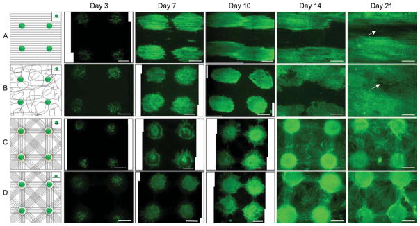
NIH 3T3 fibroblasts were seeded to aligned (A), random (B), microwell (C), and flat well (D) nanofiber membranes and incubated for 3, 7, 10, 14 and 21 days. Insets illustrated cell suspension droplet on surface of nanofiber membranes. The distance between the two adjacent microwells was 3 mm. Fluorescence microscopy images showed living cells cultured on nanofiber membranes which were stained with FDA in green. All scale bars are 1 mm.
Based on the equation where L is the distance between the micrograft skin islands, x is the side length of micrograft skin islands and Y is the expansion ratio, the expansion ratio can be tailored by changing the size of skin pieces and distances between skin pieces [27]. In order to evaluate the performance of scaffolds in skin regeneration, we firstly examined the migration and repopulation of NIH 3T3 fibroblasts seeded to individual arrayed microwells of nanofiber scaffolds in different initial cell seeding numbers at different incubation times. Here, different numbers of cells seeded to microwells of nanofiber scaffolds were used to mimic the size change of skin pieces. The scaffolds with a distance of 3 mm between two adjacent microwells were chosen to demonstrate this proof-of-concept. Figure 3 shows optical and fluorescence microcopy images of NIH 3T3 fibroblasts plated to arrayed microwells with cell numbers of 10, 100, and 1000 per well after incubation for 3, 7, 14, and 21 days respectively. The living cells were stained with FDA in green. Cells were confined within microwells composed of random nanofibers in the first 7 days of culture when seeding 10 cells at the beginning of culture. Only few cells migrated out from microwells in the same time period when initially plating 100 cells to each well. In contrast, more cells were observed in the region out of the microwells when 1000 cells were seeded to each microwell. However, no significant difference was observed for all the experimental groups after incubation for 14 and 21 days. In particular, cells can cover the whole surface of nanofiber scaffolds due to cell migration and repopulation in 21-day period of culture for experimental groups with three different cell seeding numbers.
We further investigated the cell migration and repopulation on nanofiber scaffolds with distances of 2 mm and 6 mm between microwells. Figure S4 shows optical microscopy images and fluorescence microscopy images of 100 NIH 3T3 fibroblasts which were seeded to each microwell of nanofiber scaffolds with distances between the adjacent wells of 2 mm and 6 mm for 3, 7, 14, 21 days. Similarly, living cells were stained with FDA in green. In the first 14 days of culture, cells migrated to the surrounding regions of wells and repopulated and covered the whole surface of nanofiber membranes when the distance was 2 mm between the two neighboring wells. In contrast, the cells only covered part of the surface of nanofiber membrane when the distance was 6 mm between the neighboring wells. Interestingly, the cells covered the whole surface of both nanofiber membranes after incubation for 21 days.
Our recent study reported the fabrication of radially aligned PCL nanofibers which were able to present nanotopographic cues to cultured cells, directing and enhancing their migration from the periphery to the center [21]. In this study, we combined nanofiber membranes with square arrayed microwells and radially aligned nanofibers to form sandwich-type scaffolds. Specifically, we seeded 100 NIH 3T3 fibroblasts to each microwell of nanofiber membranes with a 3-mm distance between adjacent microwells and then stacked by radially aligned nanofibers. Figure 4 shows optical microscopy images and fluorescence microscopy images of NIH 3T3 cells after culture for 3, 7, 14, 21 days on sandwich-type scaffolds. The cells migrated out of microwells composed of random nanofibers towards adjacent microwells in the first 7 days. The cells can cover the whole surface of scaffolds after incubation for 14 and 21 days.
Fig. 4.

Different numbers of NIH 3T3 fibroblasts were seeded to the microwells of nanofiber membranes and incubated for 3, 7, 14 and 21 days. The distance between the two adjacent microwells was 3 mm. Optical microscopy images showed cells cultured on nanofiber membranes in black and white. The same visual field was also shown by the corresponding fluorescence microscopy images. Living cells were stained with FDA in green.
The performance of sandwich-type nanofiber scaffolds were further tested in a rat skin excision model. In order to improve the hydrophilicity and adherence, all the scaffolds were treated with plasma in air for 5 min prior to implantation [28, 29]. Contact angle of nanofiber scaffolds changed from 135 degrees to 0 degree after plasma treatment. Figure S7 shows a schematic illustrating the formation process of nanofiber skin grafts used for implantation. Figure S7A illustrates nanofiber membranes with square arrayed microwells and structural cues. Figure S7B shows microskins sliced from the harvested skin tissues in 1-mm diameter were seeded to the microwells of scaffolds. Figure S7C shows a schematic of radially aligned nanofibers. Figure S7D illustrates sandwich-type nanofiber scaffolds were formed by transferring radially aligned nanofibers to cover microskin-seeded nanofiber membranes. The microskins were fixed in between and ready for implantation. Figure S8 shows the procedure for the transplantation of nanofiber skin grafts.
Figure 5A shows a 20-mm diameter circular full-thickness skin excision wound created on each side of the dorsal surface of a rat. It is observed that sandwich-type nanofiber scaffolds attached tightly to the wound with a uniform distribution (microskins indicated by arrow heads) and simultaneously inhibited wound contraction on day 7 post-surgery (Figure 5B). Figure 5C shows sandwich-type nanofiber scaffolds adhered tightly to wound bed, allowing drainage to pass through and adhere to covered gauze dressing on day 14 post-surgery. Besides, the scaffolds significantly inhibited wound contraction in contrast to petrolatum gauze (right side). Figure 5D shows nanofiber scaffolds adhered well to wound bed even under condition of significant wound contraction on day 21 post-surgery. Similarly, wound contraction was significantly inhibited in contrast to petrolatum gauze.
Fig. 5.

Radially-aligned nanofibers promoted the migration of cells seeded to microwell membranes. Radially-aligned nanofibers were laid on the top of nanofiber membranes immediately after seeding of 100 NIH 3T3 cells to each microwell forming a sandwich-type nanofiber scaffold which was incubated for 3, 7, 14 and 21 days. The distance between two adjacent microwells was 3 mm. Optical microscopy images showed the cells cultured on nanofiber membranes in black and white. The same visual field was also shown by the corresponding fluorescence microscopy images. Living cells were stained with FDA in green.
Histological analysis was further performed for the regenerated skin tissues. Figure 6 shows hematoxylin/eosin (H&E) staining of skin tissue sections, demonstrating that wound healing process was guided by sandwich-type nanofiber scaffolds at day 7, 14 and 21 after surgery. Black arrowheads in Figure 6(A–C) indicated the boundary between the wound and the surrounding normal skin. Figure 6A shows all transplanted microskin grafts indicated by small black arrows in sandwich-type nanofiber scaffolds which contained epithelial layer and dermal layer were ‘take’ satisfactorily by wound with a uniform distribution at day 7 post-surgery. It is observed that the microwells composed of random nanofibers were capable of confining the microskin grafts on wound bed. Figure 6D shows the magnified view of the region D in Figure 6A, which clearly demonstrating that ‘take’ microskin grafts contained epidermal layer indicated by the area between the two white dash lines and dermal layer indicated by white arrow heads. Epithelial cells derived from cutaneous appendages in microskin graft first developed epidermal cysts or columns and then extended upward to cover the wound surface. A clear boundary was seen between the dermal layer in microskin graft and the granulation tissue of host wound bed. The microwells made of random nanofibers in scaffolds indicated by black dash lines clearly showed the confinement of microskin grafts on wound bed. Inflammatory cells and red blood cells were also observed between microwells and microskins. Figure 6E shows the magnified view of the region E in Figure 6D. Small vessels and fresh red blood cells inside indicated by white arrow heads were found in the dermal layer of grafted microskins. The re-vascularization could ensure the successful graft ‘take’ by wound. Dermal layer of microskin graft was constituted by collagen bundles and few fibroblasts. Figure 6B shows re-epithelialization along the wound bed derived from microskin grafts at day 14 after surgery. Epithelial tissues laid in between dry scab and wound bed. Figure 6F shows the magnified view of the region F in Figure 6B, suggesting that cells derived from microskin grafts migrated along surface of wound bed towards the neighboring microskin grafts indicated by white dash lines resulting in re-epithelialization. The boundary of dermal layer of microskin graft indicated by white arrow heads started to fade away due to integration with dermal layer of wound bed, suggesting remodeling of microskin grafts was taking place. Epidermis became a stratified epithelium with basement membrane and formed the epithelial tongue indicated by white dash lines in wound repair. Figure 6C shows that wound were completely closed by re-epithelialization derived from microskin grafts at day 21 after surgery. Dermal layer of the microskin graft indicated by black arrows was completely integrated into surrounding granulation tissue. Figure 6G an inset in Figure 6C shows re-epithelialization on wound bed by connecting epithelial cells (indicated by white dash lines) derived from two adjacent skin islands. At the same time, the boundary of dermal layer of the microskin graft disappeared because of their complete integration with surrounding granulation tissues. Epidermis became a mature stratified epithelium with basement membrane indicated by white dash lines and the dry scab fell off from epidermis.
Fig. 6.

Micrographs showing wounds on day 0 (A), 7 (B), 14 (C) and 21 (D) after implantation of sandwich-type nanofiber scaffolds (left) and petrolatum gauze only (right). (A) One 2-cm diameter circular full-thickness skin excision wound was created on each side of the dorsal surface. (B) Nanofiber scaffolds and microskins indicated by an arrow head were evenly distributed and adhered tightly to the wound on day 7 post-surgery. (C) Nanofiber scaffolds and microskins indicated by an arrow head adhered tightly to wound bed, allowing drainage to pass through and adhere to gauze dressing on day 14 post-surgery. (D) Nanofiber scaffolds and microskins attached well to wound even significant wound contraction occurred on day 21 post-surgery indicated by an arrow head.
Figure 7 shows H&E staining of tissue sections, suggesting that the wound healing was resulted from gauze treatment at day 7, 14, and 21 after surgery. Similarly, black arrowheads indicated the boundary between the wound and the surrounding normal skin. Figure 7A shows epithelial cells were not found on wound at day 7 after surgery. Figure7D an inset in Figure 7A shows a lot of small vessels and fibroblasts grown from wound bed and the wound was repaired by fresh granulation tissue. In contrast, epithelial cell islands were not found on wound bed (Figure 7B). But epithelial cells migrated from the edge of normal skin toward the center of wound. Figure 7E an inset in Figure 7B shows the head of epithelial cell sheet indicated by white dash lines moved to the center of wound on the granulation tissue that contained small vessels and fibroblast, indicating epithelial cells derived from surrounding normal skin migrated along wound bed to repair the wound. Figure 7F an inset in Figure 7B suggests that a lot of small vessels and fibroblasts were found on wound bed at day 14 after surgery. Figure 7C shows a big wound gap still existed at day 21 after surgery and dry scab was detached from wound bed. Figure 7G (an inset in Figure 7C) shows the number of small vessels and fibroblasts dramatically decreased and the collagen content significantly increased in granulation tissue.
Fig. 7.

Representative H&E staining of skin tissue sections illustrating healing process of wound after surgical treatment of sandwich-type nanofiber scaffolds at day (A) 7, (B) 14 and (C) 21. Black arrowheads in the images indicate the boundaries between wound and surrounding normal skin. (A) Transplanted microskins indicated by small black arrows in sandwich-type nanofiber scaffolds were ‘take’ satisfactorily on wounds with a uniform distribution at day 7 post-surgery. (B) Re-epithelialization derived from microskin occurred along the wound bed at day 14 after surgery. (C) The wound was completely closed by re-epithelialization derived from microskins indicated by black arrows at day 21 after surgery. (D) Magnified view of the region D in (A), showing the ‘take’ microskin contained both epidermal layer and dermal layer indicated by white dash lines and white arrow heads, respectively, which was confined by the nanofiber microwell indicated by black dash lines. (E) Magnified view of the region E in (D), showing small blood vessels indicated by white arrow heads, large collagen bundles and few fibroblasts in dermal layer of microskin. (F) Magnified view of the region F in (B), showing stratified epithelial cells derived from microskins crept along the surface of wound bed towards the adjacent microskin indicated by white dash lines and simultaneously the dermal layer of microskins began integrating with the wound bed indicated by white arrow heads. (G) Magnified view of the region G in (C), showing epidermal cells migrated from the two adjacent microskins resurfaced the wound indicated by white dash lines.
Immunohistochemical staining of epidermal keratinocytes was performed to further reveal the difference of wound healing process when treated with sandwich-type nanofiber skin grafts and petrolatum gauzes. Keratinocytes were labeled with keratin a keratinocyte marker in red Figure 8 shows immunohistochemistry performed on skin tissue sections after sandwich-type nanofiber skin graft treatment. It is seen that transplanted microskins were ‘take’ after implantation for 7 days. Some of the transplanted microskins can still survive although the epidermal side was not up (inset in Figure 8A). At day 14 after surgery, keratinocytes migrated from the epidermis of transplanted microskins to the adjacent microskin. The wound closure was partly attributed to the re-epithelialization of transplanted microskins. At 21 day post-surgery, the wound was completely closed due to the re-epithelialization from microskins and surrounding normal skin (Figure 8C). Figure 9 shows immunohistochemistry performed on skin tissue sections after petrolatum gauzes treatment, clearly demonstrating wound closure was attributed to the re-epithelialization from surrounding normal skin. In contrast, a wound gap was still existed at 21 day post-surgery although the wound size decreased with increasing time after surgery (Figure 9C).
Fig. 8.

Representative H&E staining of skin tissue sections illustrating healing process of wound treated with petrolatum gauzes at day (A) 7, (B) 14 and (C) 21 post-surgery. Black arrowheads in the images indicated the boundaries between wound and surrounding normal skin. (A) Epithelial cells migrated from edges of normal skin toward the center of wound. (B) Epithelial cells were not found on wound bed on day 14 post-surgery. (C) A big wound gap still existed on day 21 post-surgery. (D) Magnified view of the region D in (A), demonstrating a lot of small blood vessels and fibroblasts grown from the bottom of wound bed and the wound was repaired by fresh granulation tissue. (E) Magnified view of the regions E in (B), showing epithelial cells derived from normal skin migrated along wound bed to repair the wound indicated by white dash lines and the head of epithelial cell sheet crept on the granulation tissue containing small vessels and fibroblasts. (F) Magnified view of the region F in (B), showing a lot of small blood vessels and fibroblasts on wound bed. (G) Magnified view of the region G in (C), showing wound was repaired by granulation tissue and a dramatic decrease of numbers of small vessels and fibroblasts and a significant increase of collagen content in granulation tissue.
Fig. 9.

Immunohistochemistry performed on skin tissue sections after sandwich-type nanofiber skin graft treatment for (A) 7, (B) 14, and (C) 21 days. Keratinocytes labeled with keratin a keratinocyte marker in red demonstrated re-epithelialization was mainly attributed to transplanted microskins. Inserts are larger views.
4. Discussion
Efforts have been devoted to the use of electrospun nanofibers in skin regeneration and wound healing [30, 31]. However, most of the studies focused on the creation of skin tissue construct using a tissue engineering approach – a combination of various types of cells [31], growth factors [33], antibiotics [34, 35] and electrospun nanofiber scaffolds [36–38]. The present study presented a practical approach by combining tissue engineering strategy and microskin graft for healing of skin wound, in particular, over large areas. Owning to its unique architecture, nanofiber scaffolds developed in this study presented many advantages over conventional treatments for large burn wounds.
Nanotopographic cues presented by various assemblies of electrospun nanofibers have been demonstrated to direct and enhance cell migration [26]. Previous studies demonstrated uniaxially-aligned nanofibers can guide and promote the migration of various types of cells along certain direction [20, 39]. We recently demonstrated that radially-aligned nanofiber scaffolds can direct and enhance cell migration from peripheral to the center in an ex vivo wound model [21]. Current work demonstrated cells seeded to microwells of nanofiber scaffolds can migrate along the long axis of nanofibers, repopulate and cover the whole surface of scaffolds in 2 weeks. And the combination of radially-aligned nanofiber scaffolds could further promote cell migration. In contrast, it took about 3 weeks for cells seeded to random or aligned nanofibers to cover the majority of the surface on scaffolds while small cell void areas still existed. Therefore, square arrayed microwell nanofiber scaffolds combined with radially-aligned nanofiber scaffolds may be a suitable candidate for microskin grafts as they can significantly promote cell migration between graft skin islands, which can accelerate wound closure and prevent scar formation between microskin grafts. It seems that the time for cells covering the whole surface of scaffolds is shorter than that (4–5 weeks when the mean epithelialization rate was 90%) for re-epithelialization on extensively burned patients treated by MEEK graft [40].
The Meek gauzes are now available with expansion ratios of 1:3, 1:4, 1:6 and 1:9 [41]. It is known that the expansion ratio is determined by the distance between two adjacent microskins and the size of microskins. In the present study, the distance between microwells and the diameter of microwells can be readily tailored by controlling the assembly of metal bead-capped rods and the size of metal beads. Therefore, the substrate materials developed in this study provided a flexible choice on the expansion ratio. It was reported that orientation of grafts has marginal influence on skin grafts ‘take’ when the size of skin pieces is smaller than 1 mm3 [17–19]. If the distance between adjacent skin islands is fixed on 6 mm, we can acquire expansion ratios of 1:25, 1:81, and 1:324 when the size of skin grafts are 1×1 mm, 0.5×0.5 mm, and 0.25×0.25 mm. Therefore, a large area of burn wound repaired by a limited donor skin could be realized.
One previous clinical study demonstrated the difficulty for immobilization of skin tissue suspension on the wet and lubricous wound bed [42]. Microwells presented from nanofiber scaffolds were capable of confining microskins in a square arrayed pattern and allowing microskins to adhere very well to the wound bed without applying any pressure, which could ensure the uniform epithelialization. And microwells seemed to be able to enrich nutrition, providing a microniche or 3D cellular microenvironment for blood vessel formation and revascularization and subsequently resulting in an increase of the microskin ‘take’ rate. This is very important because only serous fluid secreted from wound supports the traditional STSG grafts without blood supply in early 3–4 days and the blood flows through the anastomoses into the vessels in grafts on day 3–4 and proceeds slowly until day 5–6 [43].
Wound bed usually produced large amount of exudates and the graft failure is mainly caused by the accumulation of blood or fluid under skin graft at early stage [44]. The triangle area in the nanofiber scaffolds developed in the present study is composed of sparse fibers, which can effectively facilitate the removal of exudates. It is also observed that the nanofiber scaffolds after plasma treatment can perfectly adhere to the wound bed during wound healing process which could be due to its hydrophilicity and dispersive adhesion. We speculate that inflammatory cells or repairing cells could infiltrate into random nanofibers following fluid exudates secreted from wound and these cells could produce the human cathelicidin anti-microbial protein, which not only has broad anti-microbial activity but also induce re-epithelialization of wound [45].
Currently, re-epithelialization through STSG or CEA graft is the most popular method for wound healing in clinical practice [46]. Unfortunately, CEA graft take is not satisfying in repairing burn wound. Clinical studies showed chronic granulating wounds had a 15% ‘take’ and freshly excised or early granulating wounds had a 28–47% ‘take’ [47]. Histology results in the present study suggested a much higher microskin graft ‘take’ rate which is close to 100%. Wound healing process can be divided into several phases: contraction, inflammation, granulation tissue remodeling and re-epithelialization. It is impossible for serve burn to heal through pure wound contraction or re-epithelialization from surrounding normal skin [48, 49]. In this study, wound healing treated with nanofiber skin grafts was attributed to re-epithelialization of transplanted microskins, the wound contraction, and re-epithelialization from surrounding normal skin though nanofiber scaffolds appeared to inhibit wound contraction to some extent. Currently, scar contractions after wound closure are the main reason for function loss in extensive burn victims. The early skin grafting on wound bed can efficiently inhibit scar formation and contraction [50, 51]. In our animal model, the boundary between the dermal layer of transplanted microskins and surrounding granulation tissues was evident at day 7, started to fade away at day 14 and completely disappeared at day 21 post-surgery, suggesting the occurrence of tissue remodeling. In addition, wound re-epithelialization was also noted from the microskin grafts confined in the microwells of nanofiber scaffolds. Most interestingly, the re-epithelialization sometimes was also taking place inside the granulation tissue instead of on the surface of wound bed. After the maturation of epidermis, the granulation tissues on the surface of wound bed became dry cabs and fell off. This was different from the wound healing mechanism reported in the previous studies [52]. In order to better mimic wound healing of humans with extensive burns and better understand the mechanism of wound healing using sandwich-type nanofiber scaffolds, we will test the efficacy of the scaffolds in a pig model in the future study.
5. Conclusion
We have demonstrated the fabrication of sandwich-type nanofiber scaffolds as microskin grafts with square arrayed microwells and nanotopographic cues and their potential applications in skin injury repair. We demonstrated that NIH 3T3 fibroblasts with initial seeding densities of 100 cells per microwell can cover the entire surface of microwell scaffolds within 14 days in vitro due to their repopulation and migration when the distance between two adjacent microwells was 3 mm, while it took more than 21 days for cells to cover the whole surface of random or aligned nanofiber membranes. NIH 3T3 fibroblasts with initial seeding densities of 10, 100 and 1000 cells per microwell can also migrate, repopulate and cover the whole surface of scaffolds within 21 days in vitro when the distances between two adjacent microwells were 3 and 6 mm, respectively. In addition, primary rat skin cells showed the similar behavior as NIH 3T3 fibroblasts. We further demonstrated that the sandwich-type nanofiber scaffolds were capable of presenting a uniform distribution of microskin grafts, enhancing the ‘take’ rate of microskin grafts and accelerating re-epithelialization on wounds in a rat skin excision injury model. These results suggested sandwich-type nanofiber scaffolds could offer a promising solution in skin regeneration on extensive burns and provide a suitable carrier for STSG graft in skin regeneration for acute skin defects or chronic wounds.
Supplementary Material
Fig. 10.

Immunohistochemistry performed on skin tissue sections after petrolatum gauzes treatment for (A) 7, (B) 14, and (C) 21 days. Keratinocytes labeled with keratin a keratinocyte marker in red demonstrated the re-epithelialization was attributed to surrounding normal skins. Inserts are larger views.
Acknowledgments
This work was supported in part by grant number UL1RR033173 from the National Center for Research Resources (NCRR), funded by the office of the Director, National Institutes of Health (NIH) and supported by the NIH roadmap for Medical Research and start-up funds from Marshall Institute for Interdisciplinary Research and Center for Diagnostic Nanosystems at Marshall University. We thank Dr. Qizhi Luo (Institute of Burn Research, Southwest Hospital, Chongqing, China) for helpful discussion in skin transplantation. We thank Dr. Wen-Wu Li (Department of Orthopaedic Surgery, Stanford University) and Dr. David J. Clark (Department of Anesthesia, Stanford University) for the help in immunohistochemical staining of rat keratinocytes.
Footnotes
Conflict of interest
The authors have no conflicts of interest to declare.
Publisher's Disclaimer: This is a PDF file of an unedited manuscript that has been accepted for publication. As a service to our customers we are providing this early version of the manuscript. The manuscript will undergo copyediting, typesetting, and review of the resulting proof before it is published in its final citable form. Please note that during the production process errors may be discovered which could affect the content, and all legal disclaimers that apply to the journal pertain.
References
- 1.Orgill DP. Excision and skin grafting of thermal burns. N Engl J Med. 2009;360:893–901. doi: 10.1056/NEJMct0804451. [DOI] [PubMed] [Google Scholar]
- 2.Finkelstein EA, Corso PS, Miller TR. Incidence and economic burden of injuries in the United States. New York: Oxford University Press; 2006. [Google Scholar]
- 3.Falanga V, Faria K, Rober L, Joseph V. Principles of Tissue Engineering. 3. Burlington: Academic Press; 2007. Bioengineered skin constructs. [Google Scholar]
- 4.Bishara SA, Michel C. Cultured epithelial autograft (CEA) in burn treatment: three decades later. Burns. 2007;33:405–13. doi: 10.1016/j.burns.2006.11.002. [DOI] [PubMed] [Google Scholar]
- 5.Chester DL, Balderson DS, Papini RPG. A review of keratinocyte delivery to the wound bed. J Burn Care Rehab. 2004;25:266–75. doi: 10.1097/01.bcr.0000124749.85552.cd. [DOI] [PubMed] [Google Scholar]
- 6.Williamson JS, Snelling CFT, Clugston P, Macdonald IB, Germann E. Cultured epithelial autograft: five years of clinical experience with twenty-eight patients. J Trauma. 1995;39:309–19. doi: 10.1097/00005373-199508000-00020. [DOI] [PubMed] [Google Scholar]
- 7.Green H. Cultured cells for the treatment of disease. Sci Am. 1991;265:96–102. doi: 10.1038/scientificamerican1191-96. [DOI] [PubMed] [Google Scholar]
- 8.Ronfard V, Rives JM, Neveux Y, Carsin H, Barrandon Y. Long-term regeneration of human epidermis on third degree burns transplanted with autologous cultured epithelium grown on a fibrin matrix. Transplantation. 2000;70:1588–98. doi: 10.1097/00007890-200012150-00009. [DOI] [PubMed] [Google Scholar]
- 9.Odessey R. Addendum: multicenter experience with cultured epidermal autograft for treatment of burns. J Burn Care Rehabil. 1992;13:174–80. [PubMed] [Google Scholar]
- 10.Leon-Villapalos J, Eldardiri M, Dziewulski P. The use of human deceased donor skin allograft in burn care. Cell Tissue Bank. 2010;11:99–104. doi: 10.1007/s10561-009-9152-1. [DOI] [PubMed] [Google Scholar]
- 11.Ong YS, Samuel M, Song C. Meta-analysis of early excision of burns. Burns. 2006;32:145–50. doi: 10.1016/j.burns.2005.09.005. [DOI] [PubMed] [Google Scholar]
- 12.Sophie BH, Thomas B, Ernst R. Tissue engineering of skin. Burns. 2010;36:450–60. doi: 10.1016/j.burns.2009.08.016. [DOI] [PubMed] [Google Scholar]
- 13.Chen XL, Liang X, Sun L, Wang F, Liu S, Wang YJ. Microskin autografting in the treatment of burns over 70% of total body surface area: 14 years of clinical experience. Burns. 2011;37:973–80. doi: 10.1016/j.burns.2011.03.022. [DOI] [PubMed] [Google Scholar]
- 14.Lumenta DB, Kamolz LP, Frey M. Adult burn patients with more than 60% TBSA involved-Meek and other techniques to overcome restricted skin harvest availability—the Viennese Concept. J Burn Care Res. 2009;30:231–42. doi: 10.1097/BCR.0b013e318198a2d6. [DOI] [PubMed] [Google Scholar]
- 15.Aiyer PM, Gower JP. The mesh skin graft is very useful in the resurfacing of large burns. Burns. 1999;25:467. doi: 10.1016/s0305-4179(99)00008-x. [DOI] [PubMed] [Google Scholar]
- 16.Kreis RW, Mackie DP, Hermans RR, Vloemans AR. Expansion techniques for skin grafts: comparison between mesh and Meek island (sandwich-) grafts. Burns. 1994;20(Suppl 1):S39–S42. doi: 10.1016/0305-4179(94)90088-4. [DOI] [PubMed] [Google Scholar]
- 17.Zhang ML, Chang ZD, Han X, Zhu M. Microskin grafting. I. Animal experiments. Burns Incl Therm Inj. 1986;12:540–43. doi: 10.1016/0305-4179(86)90002-1. [DOI] [PubMed] [Google Scholar]
- 18.Zhang ML, Wang CY, Chang ZD, Cao DX, Han X. Microskin grafting. II. Clinical report. Burns Incl Therm Inj. 1986;12:544–48. doi: 10.1016/0305-4179(86)90003-3. [DOI] [PubMed] [Google Scholar]
- 19.Zhang ML, Chang ZD, Wang CY, Fang CH. Microskin grafting in the treatment of extensive burns: a preliminary report. J Trauma. 1988;28:804–7. [PubMed] [Google Scholar]
- 20.Xie J, Liu W, MacEwan MR, Yeh YC, Thomopoulos S, Xia Y. Nanofiber membranes with controllable microwells and structural cues and their use in forming cell microarrays and neuronal networks. Small. 2011;7:293–7. doi: 10.1002/smll.201001446. [DOI] [PMC free article] [PubMed] [Google Scholar]
- 21.Xie J, MacEwan MR, Ray WZ, Liu W, Siewe DY, Xia Y. Radially aligned, electrospun nanofibers as dural substitutes for wound closure and tissue regeneration applications. ACS Nano. 2010;4:5027–36. doi: 10.1021/nn101554u. [DOI] [PMC free article] [PubMed] [Google Scholar]
- 22.Gu Q, Xing JZ, Huang M, He C, Chen J. SN-38 loaded polymeric micelles to enhance cancer therapy. Nanotechnology. 2012;23:205101. doi: 10.1088/0957-4484/23/20/205101. [DOI] [PubMed] [Google Scholar]
- 23.Pastorino L, Pioli F, Zilli M, Converti A, Nicolini C. Lipase-catalyzed degradation of poly(ε-caprolactone) Enzyme Microb Tech. 2004;35:321–6. [Google Scholar]
- 24.Kweon H, Yoo MK, Park IK, Kim TH, Lee HC, Lee HS, et al. A novel degradable polycaprolactone networks for tissue engineering. Biomaterials. 2003;24:801–8. doi: 10.1016/s0142-9612(02)00370-8. [DOI] [PubMed] [Google Scholar]
- 25.Li WW, Guo TZ, Li XQ, Kingery WS, Clark JD. Fracture induces keratinocyte activation, proliferation, and expression of pro-nociceptive inflammatory mediators. Pain. 2010;151:843–52. doi: 10.1016/j.pain.2010.09.026. [DOI] [PMC free article] [PubMed] [Google Scholar]
- 26.Schnell E, Klinkhammer K, Balzer S, Brook G, Klee D, Dalton P, et al. Guidance of glial cell migration and axonal growth on electrospun nanofibers of poly-epsilon-caprolactone and a collagen/poly-epsilon-caprolactone blend. Biomaterials. 2007;28:3012–25. doi: 10.1016/j.biomaterials.2007.03.009. [DOI] [PubMed] [Google Scholar]
- 27.Lin TW. The algebraic view-point in microskin grafting in burned patients. Burns. 1994;20:347–50. doi: 10.1016/0305-4179(94)90065-5. [DOI] [PubMed] [Google Scholar]
- 28.Prabhakaran MP, Venugopal J, Chan CK, Ramakrishna S. Surface modified electrospun nanofibrous scaffolds for nerve tissue engineering. Nanotechnology. 2008;19:455102. doi: 10.1088/0957-4484/19/45/455102. [DOI] [PubMed] [Google Scholar]
- 29.Martins A, Pinho ED, Faria S, Pashkuleva I, Marques AP, Reis RL, et al. Surface modification of electrospun polycaprolactone nanofiber meshes by plasma treatment to enhance biological performance. Small. 2009;5:1195–206. doi: 10.1002/smll.200801648. [DOI] [PubMed] [Google Scholar]
- 30.Zhong SP, Zhang YZ, Lim CT. Tissue scaffolds for skin wound healing and dermal reconstruction. Wiley Interdiscip Rev Nanomed Nanobiotechnol. 2010;2:510–25. doi: 10.1002/wnan.100. [DOI] [PubMed] [Google Scholar]
- 31.Kumbar SG, James R, Nukavarapu SP, Laurencin CT. Electrospun nanofiber scaffolds: engineering soft tissues. Biomed Mater. 2008;3:034002. doi: 10.1088/1748-6041/3/3/034002. [DOI] [PubMed] [Google Scholar]
- 32.Jin G, Prabhakaran MP, Ramakrishna S. Stem cell differentiation to epidermal lineages on electrospun substrates for skin tissue engineering. Acta Biomater. 2011;7:3113–22. doi: 10.1016/j.actbio.2011.04.017. [DOI] [PubMed] [Google Scholar]
- 33.Yang Y, Xia T, Zhi W, Wei L, Weng J, Zhang C, et al. Promotion of skin regeneration in diabetic rats by electropsun core-sheath fibers loaded with basic fibroblast growth factor. Biomaterials. 2011;32:4243–54. doi: 10.1016/j.biomaterials.2011.02.042. [DOI] [PubMed] [Google Scholar]
- 34.Unnithan AR, Barakatt NA, Tirupathi Pichiah PB, Gnanasekaran G, Nirmala R, Cha YS, et al. Wound-dressing materials with antibacterial activity from electrospun polyurethane-dextran nanofiber mats containing ciprofloxacin HCl. Carbohydr Polym. 2012;90:1786–93. doi: 10.1016/j.carbpol.2012.07.071. [DOI] [PubMed] [Google Scholar]
- 35.Chen JP, Chiang Y. Bioactive electrospun silver nanoparticles-containing polyurethane nanofibers as wound dressings. J Nanosci Nanotechnol. 2010;10:7560–4. doi: 10.1166/jnn.2010.2829. [DOI] [PubMed] [Google Scholar]
- 36.Chandrasekaran AR, Venugopal J, Sundarrajan S, Ramakrishna S. Fabrication of a nanofibrous scaffold with improved bioactivity for culture of human dermal fibroblasts for skin regeneration. Biomed Mater. 2011;6:015001. doi: 10.1088/1748-6041/6/1/015001. [DOI] [PubMed] [Google Scholar]
- 37.Gumusderelioglu M, Dalkiranoglu S, Aydin RS, Cakmak S. A novel dermal substitute based on biofunctionalized electrospun PCL nanofibrous matrix. J Biomed Mater Res A. 2011;98:461–72. doi: 10.1002/jbm.a.33143. [DOI] [PubMed] [Google Scholar]
- 38.Tchemtchoua VT, Atanasova G, Agil A, Filee P, Garbacki N, Vanhooteghem O, et al. Development of a chitosan nanofibrillar scaffold for skin repair and regeneration. Biomarcromolecules. 2011;12:3194–204. doi: 10.1021/bm200680q. [DOI] [PubMed] [Google Scholar]
- 39.Corey JM, Lin DY, Mycek KB, Chen Q, Samuel S, Feldman EL, et al. Aligned electrospun nanofibers specify the direction of dorsal root ganglia neurite growth. J Biomed Mater Res A. 2007;83:636–645. doi: 10.1002/jbm.a.31285. [DOI] [PubMed] [Google Scholar]
- 40.Lari AR, Gang RK. Expansion technique for skin grafts (MEEK technique) in the treatment of severely burned patients. Burns. 2001;27:61–6. doi: 10.1016/s0305-4179(00)00066-8. [DOI] [PubMed] [Google Scholar]
- 41.Hsieh CS, Schuong JY, Huang WS, Huang TT. Five years’ experience of the modified Meek technique in the management of extensive burns. Burns. 2008;34:350–4. doi: 10.1016/j.burns.2007.05.005. [DOI] [PubMed] [Google Scholar]
- 42.Ma D, Liu M, Ma B, Wang XJ, Pen Y, Zhang P, et al. A novel method for wound healing—skin suspension accelerates donor site wound healing. Wounds. 2011;23:107–10. [PubMed] [Google Scholar]
- 43.Converse JM, Smahel J, Ballentyne DL. Inosculation of vessels of skin graft and host bed: a fortuitous encounter. Br J Plast Surg. 1975;28:274–82. doi: 10.1016/0007-1226(75)90031-4. [DOI] [PubMed] [Google Scholar]
- 44.Hierner R, Degreef H, Vranckx JJ, Garmyn M, Massage P, van Brussel M. Skin grafting and wound healing-the ‘dermato-plastic team approach’. Clin Dermatol. 2005;23:343–52. doi: 10.1016/j.clindermatol.2004.07.028. [DOI] [PubMed] [Google Scholar]
- 45.Johan DH, Margareta FN, Gunnar K, Gunther W, Ole S, Niels B, et al. The cathelicidin anti-microbial peptide IL-37 is involved in re-epithelialization of human skin wounds and is lacking in chronic ulcer epithelium. J Invest Dermatol. 2003;120:379–89. doi: 10.1046/j.1523-1747.2003.12069.x. [DOI] [PubMed] [Google Scholar]
- 46.Bottcher-Haberzeth S, Biedermann T, Reichmann E. Tissue engineering of skin. Burns. 2010;36:450–60. doi: 10.1016/j.burns.2009.08.016. [DOI] [PubMed] [Google Scholar]
- 47.Orgill D, Butler C, Regan J, Barlow M, Yanna IV, Compton CC. Vascularized collagen-glycosaminoglycan matrix provides a dermal substrate and improves take of cultures epithelial autografts. Plast Reconstr Surg. 1998;102:423–9. doi: 10.1097/00006534-199808000-00020. [DOI] [PubMed] [Google Scholar]
- 48.Eldardiri M, Martin Y, Roxburgh J, Lawrence-Watt DJ, Sharpe JR. Wound contraction is significantly reduced by the use of microcarriers to deliver keratinocytes and fibroblasts in an in vivo pig model of wound repair and regeneration. Tissue Eng Part A. 2012;18:587–97. doi: 10.1089/ten.TEA.2011.0258. [DOI] [PubMed] [Google Scholar]
- 49.Martin P. Wound healing—aiming for perfect skin regeneration. Science. 1997;276:75–81. doi: 10.1126/science.276.5309.75. [DOI] [PubMed] [Google Scholar]
- 50.Aarabi S, Longaker MT, Gurtner GC. Hypertrophic scar formation following burns and trauma: new approaches to treatment. PLoS Med. 2007;4(9):e234. doi: 10.1371/journal.pmed.0040234. [DOI] [PMC free article] [PubMed] [Google Scholar]
- 51.Chan QE, Harvey JG, Graf NS, Godfrey C, Holland AJ. The correlation between time to skin grafting and hypertrophic scarring following an acute contact burn in a porcine model. J Burn Care Res. 2012;33(2):e43–8. doi: 10.1097/BCR.0b013e31823356ce. [DOI] [PubMed] [Google Scholar]
- 52.Singer AJ, Clark RA. Cutaneous wound healing. N Engl J Med. 1999;341:738–46. doi: 10.1056/NEJM199909023411006. [DOI] [PubMed] [Google Scholar]
Associated Data
This section collects any data citations, data availability statements, or supplementary materials included in this article.