Abstract
OBJECTIVE
We sought to assess the effectiveness of a novel computed tomography (CT) radiation dose-reduction strategy in which filtration was added at the x-ray tube output port between the x-ray beam and the breast area of three sizes of anthropomorphic phantoms.
METHODS
To evaluate the dose-reduction potential of partial arc x-ray beam filtration, copper foil filtration or lead foil filtration was placed over CT scanners’ covers when scanning anthropomorphic phantoms representative of a 5-year-old, 10-year-old, and an adult female. Dose reduction was calculated as the percent difference between the mean entrance radiation dose (detected on the phantoms’ surfaces at locations representing the sternum and left breast) in unshielded scans compared to the mean dose in scans shielded by copper foil or lead foil. Additionally, we compared the CT numbers and noise sampled in regions representing the lung and the soft tissues near the sternum, left breast, and spine in CT images of the phantoms during unshielded scans relative to acquisitions shielded copper foil or lead foil.
RESULTS
Entrance dose at the sternum and left breast in the three anthropomorphic phantoms was reduced by 28% to 66% and 54% to 79% when using copper foil or lead foil filtration, respectively. However, copper foil filtration affected the CT numbers and noise in the CT images less than the lead foil filtration (8.2% versus 32% mean increase in noise, respectively).
CONCLUSION
By incorporating partial arc beam filtration into CT scanners, substantial dose reductions may be achieved with a minimal increase in image noise.
Keywords: computed tomography, chest CT, breast dose, organ dose, breast shields
Introduction
Many routine computed tomography (CT) examinations which incidentally expose breast tissue may put patients at risk for developing breast cancer [1]. Thus, CT breast dose must be given special consideration. Although several overall dose-reduction strategies (e.g., tube current modulation [TCM] and iterative reconstruction) have been implemented in CT scanners, few strategies exist that specifically target breast tissue. One such strategy (X-care; Siemens Healthcare, Erlangen, Germany) either greatly lowers or turns off the x-ray tube current (i.e., 0 milliamperes [mA]) at angular tube positions where the x-ray beam is directly exposing a patient's breast tissue. A potential limitation of this approach is that the x-ray tube current must be turned on for a sufficient enough portion of the rotation to support image reconstruction, which limits the effectiveness of this technology when scanning women whose breast tissue lies within this region. Furthermore, the posterior tube current is often increased to maintain image quality which can result in higher spine doses, and this strategy has only been implemented by one manufacturer to date [2].
Another strategy specifically aimed at reducing CT breast dose involves covering the breast tissue with in-plane shielding during scanning [3]. In-plane breast shields (typically bismuth-based) are used to partially attenuate the x-ray beam before it enters the body, reducing dose to the underlying tissue. Unlike X-Care, bismuth breast shields function independently of the CT scanner and thus can be used across scanners of different models and from different manufacturers. Although bismuth breast shields have been reported to reduce CT radiation dose absorbed by the breast tissue, degraded quality of the CT images has also been reported, which has limited the acceptance of this technology by some medical physicists [4, 5]. Specifically, in-plane breast shields attenuate the x-ray beam not only before it enters a patient (i.e., when the x-ray tube is facing the patient's anterior), but also after the beam exits the patient (i.e., when the tube is facing the patient's posterior) which can increase the mean energy and reduce the number of photons that reach the detectors, resulting in artifacts, image noise, and a shift in CT numbers [6].
As shown in a prior study, the CT number shift associated with in-plane breast shielding, along with image noise and the presence of streak artifacts, was reduced by increasing the offset between the shield and the phantom [7]. Furthermore, Kalra et al. found that surface dose did not significantly change when the distance between the shield and phantom was increased. Therefore, it is conceivable that the negative impact of beam shielding on image quality could be minimized, while maintaining a constant level of dose reduction, by maximizing the offset distance between the shield and the phantom (i.e., filtering the primary x-ray beam as it emerges from the output port). To accomplish this, a physical filter made of a dense material (e.g., lead, copper, etc.) could be placed in the x-ray beam's path when it is directly exposing a patient's breast tissue; we will refer to this strategy as partial arc beam filtration. Compared to bismuth breast shields and X-Care, partial arc beam filtration could be applied over any angular region, which could be coordinated with the location of a patient's breast tissue, and is assumed not to increase spine dose.
The purpose of this study was to investigate the effect of partial arc beam filtration on CT dose, CT number, image noise, and streak artifacts. To do so, we secured lead and copper foil over a portion of the gantry cover on two models of CT scanners. Pediatric and adult anthropomorphic phantoms were then scanned using clinical chest protocols with TCM and with and without iterative reconstruction to evaluate the potential of partial arc beam filtration when combined with existing dose-reduction strategies.
Materials and Methods
Transmission measurements
Prior to evaluating the proposed strategy (partial arc beam filtration), transmitted exposure through bismuth breast shields (AttenuRad CT breast shield system; F&L Medical Products, Vandergrift, PA), copper foil tape (CFL-5A; J.V. Converting Company, Inc., Fairless Hills, PA), and lead foil tape (LF-5A; J.V. Converting Company, Inc.) was detected with the standard setup used for half-value layer estimation [8]. A Farmer ionization chamber connected to an electrometer (RadCal Corporation, Monrovia, CA) was used to detect exposure. Transmission percentages were calculated relative to exposure detected for an unattenuated beam (i.e., no filtration or shielding at the bottom of the gantry). These results were used to determine the thicknesses of copper foil and lead foil that had roughly the same transmission as through the bismuth breast shields.
Scanning techniques
A LightSpeed VCT and a Discovery CT750 HD scanner (GE Healthcare, Waukesha, WI) were used to scan anthropomorphic phantoms representative of a 5-year-old, 10-year-old, and an adult upper torso (with breast attachments) (ATOM family; CIRS, Norfolk, VA). Each phantom was placed on the patient tabletop and centered within the bore of the scanners’ gantries using the scanners’ laser positioning lights; CT images were used to verify centering. Localizer projection radiographs (scouts) were acquired without any added filtration or shielding. A technique of 10 mA and 80 kVp or 120 kVp was used for the pediatric or adult phantom scouts, respectively. All scouts were acquired using a 180° scout plane (i.e., a posteroanterior projection).
Entrance (skin) radiation exposures were then detected without added beam filtration or shielding, with in-plane bismuth breast shielding, and with copper foil or lead foil partial beam filtration using an ionization chamber. The ionization chamber was placed on the phantoms’ surfaces at locations representing the sternum and left breast, which for the 5-year-old and 10-year-old phantoms was approximately 4 cm and 5 cm, respectively, to the left of the sternums and was at the left nipple for the adult phantom. The phantoms were scanned with a helical pass from the chin to roughly the diaphragm using the clinical TCM protocols listed in Table 1, which specified both a noise index (NI) and the range (i.e., minimum and maximum) within which the x-ray tube current could be modulated [9]. For the GE LightSpeed VCT scanner, the tube currents used in the TCM schemes for the 5 year-old, 10 year-old, and adult phantoms ranged from 46 to 123 mA (mean: 96 mA), 41 – 78 mA (mean: 64 mA), and 37 - 259 mA (mean: 191 mA), respectively. For the GE Discovery CT750 HD scanner, the tube currents used in the TCM schemes for the 5 year-old, 10 year-old, and adult phantoms ranged from 47 to 111 mA (mean: 88 mA), 36 – 77 mA (mean: 63 mA), and 37 - 245 mA (mean: 182 mA), respectively. On the Discovery CT750 HD scanner, adaptive statistical iterative reconstruction (ASiR; GE Healthcare) was also employed during the scans (a level of 40% ASiR was chosen in accordance with recommendations from Karen Procknow of GE Healthcare [via personal communication, 3/4/2011]). To account for this level of ASiR, the TCM protocols were adjusted by scaling the NI by a factor of 1.3 ( as specified in [10]). Adding ASiR reduced the range of tube currents used in the TCM schemes for the 5 year-old, 10 year-old, and adult phantoms to 35 – 66 mA (mean: 52 mA), 35 – 46 mA (mean: 38 mA), and 38 - 145 mA (mean: 109 mA), respectively. ASiR was not installed on the LightSpeed VCT scanner, and thus was only employed during scans on the Discovery CT750 HD scanner. Ten exposure measurements were collected at the sternum and the left breast for each phantom and scanner.
TABLE 1.
TCM Protocols Used For Scanning the Anthropomorphic Phantomsa
| Phantom | NIb | Tube Current Range (mA) | kVp | DFOV (cm) | SFOV |
|---|---|---|---|---|---|
| 5-year-old | 21 or 27.3 | 35 – 230 | 80 | 25 | Pediatric body |
| 10-year-old | 21.5 or 27.95 | 35 – 300 | 100 | 29 | Pediatric body |
| Adult | 22 or 28.6 | 35 – 360 | 120 | 50 | Medium body |
Note: TCM = tube current modulation, NI = noise index, DFOV = display field of view, SFOV = scan field of view
40-mm beam width, 2.5-mm helical image thickness, 0.984 pitch, and 0.4-s rotation times were used for all scans.
The higher noise index was used for scans with adaptive statistical iterative reconstruction, which were performed on the Discovery CT750 HD scanner only; the lower noise index was used for scans without adaptive statistical iterative reconstruction, which were performed on both scanners.
Unshielded scanning
The three phantoms were initially scanned (using the protocols listed in Table 1) and exposures were detected without any added filtration or shielding.
In-plane bismuth breast shielding
Scans were repeated and exposure measurements were collected with in-plane bismuth breast shields placed on the phantoms’ surfaces. The breast shields used on the pediatric and adult phantoms contained 0.5 mm and 1 mm of bismuth (0.03-mm and 0.06-mm lead equivalence), respectively, impregnated in synthetic rubber. Each shield was mounted to a 1-cm foam base.
Partial arc beam filtration
Subsequently, scanning was performed with high-purity (≥ 99.9%) copper or lead foil placed over the scanners’ Mylar windows, as shown in Figure 1, and exposures were recorded. Copper and lead were selected to evaluate the proposed strategy (partial arc beam filtration) because these materials are commonly used in radiological applications and they could be acquired relatively inexpensively in high-purity foils with the desired dimensions (i.e., the width of the copper and lead foils [76 mm] matched that of the gantries’ Mylar windows). Lengths of the foils were sized to match the angular regions on the phantoms covered by the in-plane bismuth breast shields, which were approximately 140° for the 5-year-old and adult phantoms and 150° for the 10-year-old phantom (see Fig. 2). Four or eight layers of 0.0356-mm thick copper foil tape were placed over the scanners’ Mylar windows when scanning the pediatric phantoms or the adult phantom, respectively; these thickness were chosen based on the results obtained from the initial transmission measurements. Because the 0.127-mm thick lead foil tape was thicker than the lead equivalence of bismuth in the breast shields, only one layer of lead foil was placed over the Mylar windows for all three of the phantoms.
Fig. 1.
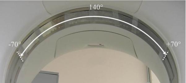
The lead and copper foil tape covered a 140° arc of the CT scanners’ Mylar windows when scanning the 5-year-old and adult phantoms and a 150° arc when scanning the 10-year old phantom.
Fig. 2.
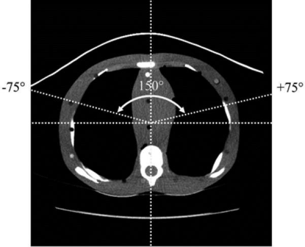
The angular regions covered by the bismuth breast shields when scanning each of the phantoms was determined from the CT images; as shown here, 150° of the Mylar window was covered when scanning the 10-year-old phantom.
Dose analysis
The average of the ten exposure measurements (in units of R) collected for each phantom, scanner, and dose measurement location was converted to dose (in units of mGy) using an exposure-to-dose conversion factor (f-factor) of 9.4 mGy/R [11]. Dose reductions were calculated as the percent differences between the mean doses with bismuth breast shielding, copper foil beam filtration, or lead foil beam filtration relative to the unshielded scans with TCM only (i.e., without ASiR). Dose reductions for the unshielded scans with ASiR (performed on the GE Discovery CT750 HD scanner only) were also calculated to determine the dose savings from ASiR alone (i.e., without the effect of shielding or filtration).
Image analysis
To evaluate the CT images, regions of interest (ROIs) were sampled in the representative soft tissues anterior to the sternum and within the left breast, in the representative posterior soft tissue near the spine, and in the lungs; Figure 3 shows the sizes and specific locations of the four ROIs for each phantom. Within each ROI location, phantom, and scanner, we compared the CT numbers and noise level (in Hounsfield units [HU]) for the unshielded scans to those with in-plane bismuth breast shielding and with copper foil or lead foil filtration. The mean shift in the CT numbers and the mean percent difference in noise were determined.
Fig. 3.
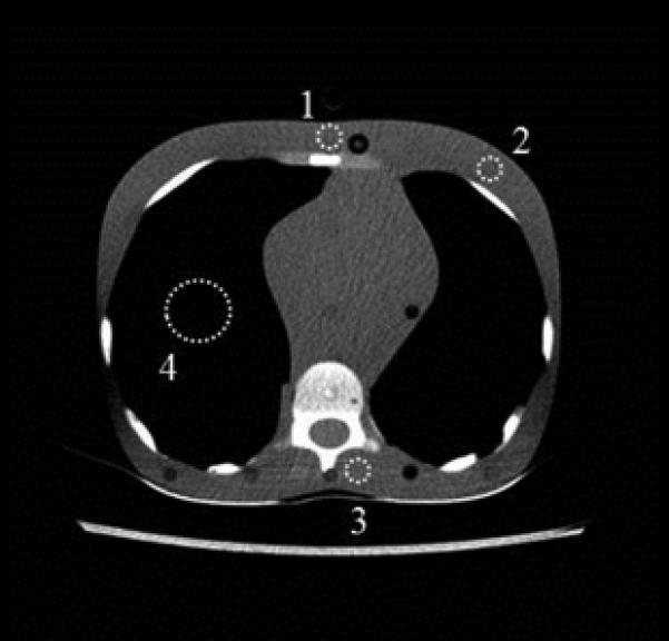
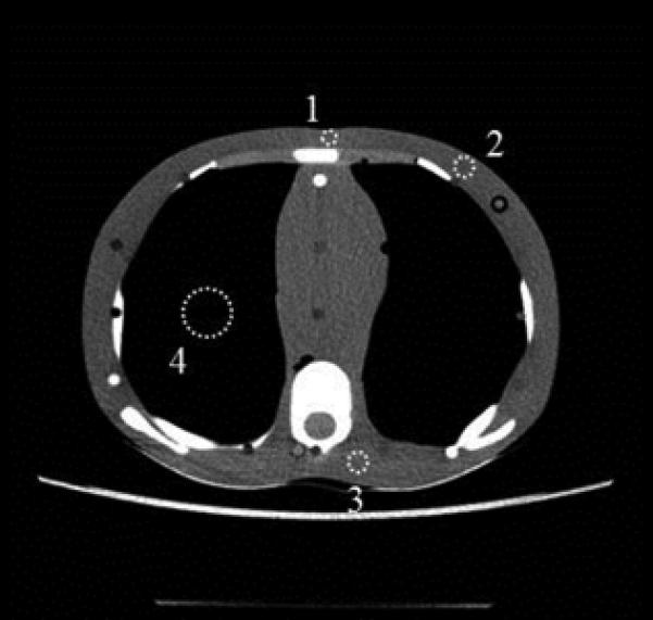
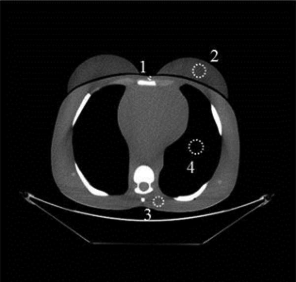
ROIs were drawn at the sternum (labeled “1”), the left breast (labeled “2”), in the posterior soft tissue near the spine (labeled “3”), and in the lung (labeled “4”).
A, 5-year-old phantom; ROIs “1”, “2”, and “3” were 0.61 cm2 and ROI “4” was 4.3 cm2 in size.
B, 10-year-old phantom; ROI “1” was 0.36 cm2, ROIs “2” and “3” were 0.65 cm2, and ROI “4” was 4.0 cm2 in size.
C, Adult phantom; ROI “1” was 0.27 cm2, ROIs “2” and “4” were 4.3 cm2, and ROI “3” was 2.4 cm2 in size.
Results
Transmission measurements
The percentages of radiation transmitted through the bismuth breast shields, copper foil filtration, and lead foil filtration are shown in Table 2.
TABLE 2.
Percentages of Exposure Transmitted through Bismuth Breast Shields and Foil Beam Filtration
| Filtration or Shielding | Transmitted Exposure (%)a |
|---|---|
| 5-year-old bismuth breast shield (0.5 mm; 0.03-mm lead equivalence) | 71 |
| 10-year-old bismuth breast shield (0.5 mm; 0.03-mm lead equivalence) | 73 |
| Adult bismuth breast shield (1 mm; 0.06-mm lead equivalence) | 54 |
| Lead foil tape (1 layer [0.127 mm]) | 38 |
| Copper foil tape (4 layers [0.1424 mm]) | 72 |
| Copper foil tape (8 layers [0.2848 mm]) | 55 |
The transmission percentages were calculated relative to exposure measured for an unattenuated beam (i.e., no shielding or filtration).
Dose analysis
The radiation doses and the percentages of dose reduction achieved for all shielding conditions and phantoms using both the LightSpeed VCT and Discovery CT750 HD scanners are listed in Table 3. Entrance dose was reduced by 54% to 80% (1.12 - 8.00 mGy) across all phantoms, both scanners, and both measurement locations (sternum and left breast) when using lead foil beam filtration; in every case, lead foil filtration achieved greater reductions in entrance dose compared to the other two shielding conditions. The range of entrance dose savings from using copper foil beam filtration (28 - 66% or 0.57 – 6.86 mGy) was roughly the same as that achieved by bismuth breast shields (22 - 68% or 0.43 – 7.08 mGy). The percentages of dose reduction were greater for the scans performed on the Discovery CT750 HD than those performed on the LightSpeed VCT (for the same shielding condition and phantom) because of the added effect of ASiR; dose reductions due to ASiR alone ranged from 30% to 44% (or up to 4.30 mGy), which agreed with expectations based on the ASiR level chosen (i.e., 40%). For unshielded scans without ASiR, the detected radiation doses and the TCM schemes were similar across the two scanners despite differences between the scanners (e.g., the Discovery CT750 HD scanner uses gemstone detector technology and a different x-ray tube with dual-energy capability).
TABLE 3.
Calculated Dose Estimatesa and the Corresponding Percentages of Dose Reductionb for the Anthropomorphic Phantoms
| Dose Measurement Location | Filtration or Shielding | GE LightSpeed VCT Scanner | GE Discovery CT750 HD Scanner | ||||
|---|---|---|---|---|---|---|---|
| 5-Year-Old Phantom | 10-Year-Old Phantom | Adult Phantom | 5-Year-Old Phantom | 10-Year-Old Phantom | Adult Phantom | ||
| Sternum | Unshielded (TCM w/o ASiR) | 2.59 | 2.05 | 9.98 | 2.32 | 2.17 | 10.4 |
| Unshielded (TCM w/ ASiR) | N/A | N/A | N/A | 1.38 (41%) | 1.43 (34%) | 6.10 (42%) | |
| Bismuth breast shield | 1.72 (34%) | 1.59 (23%) | 5.87 (41%) | 0.90 (61%) | 1.05 (51%) | 3.32 (68%) | |
| Copper foil | 1.70 (34%) | 1.47 (28%) | 5.74 (42%) | 0.86 (63%) | 0.99 (55%) | 3.54 (66%) | |
| Lead foil | 1.04 (60%) | 0.83 (60%) | 4.52 (55%) | 0.48 (79%) | 0.61 (72%) | 2.40 (77%) | |
| Left breast | Unshielded (TCM w/o ASiR) | 2.42 | 1.93 | 7.69 | 2.26 | 1.95 | 6.82 |
| Unshielded (TCM w/ ASiR) | N/A | N/A | N/A | 1.27 (44%) | 1.29 (34%) | 4.78 (30%) | |
| Bismuth breast shield | 1.58 (35%) | 1.50 (22%) | 4.85 (37%) | 0.83 (64%) | 0.96 (51%) | 2.73 (60%) | |
| Copper foil | 1.63 (33%) | 1.36 (30%) | 4.78 (38%) | 0.84 (63%) | 0.92 (53%) | 2.69 (61%) | |
| Lead foil | 0.96 (60%) | 0.81 (58%) | 3.53 (54%) | 0.46 (79%) | 0.56 (71%) | 1.86 (73%) | |
Note: TCM = tube current modulation, ASiR = adaptive statistical iterative reconstruction
Dose was estimated for scans using the clinical TCM and ASiR protocols listed in Table 1; dose estimates are given in units of milligray (mGy).
Dose reduction, which is listed in parentheses below the dose estimates, was calculated relative to the unshielded scan without ASiR.
Image analysis
Figure 4 shows the reconstructed CT images for the adult phantom scanned using the GE Discovery CT750 HD scanner. Streak artifacts can be seen in the CT images of the adult phantom when in-plane bismuth breast shielding was used and also when copper or lead foil filtration was used. While breast shielding resulted in streak artifacts within the phantom anatomy, when copper or lead foil was used, the artifacts were at the edge of the display field of view (DFOV), beyond the anatomy of the phantom. In the CT images of the 5-year-old and 10-year-old phantoms (not shown), streak artifacts were observed within the phantom anatomy when using bismuth breast shields, but artifacts were not observed when using copper or lead foil filtration, which can be explained by the use of smaller DFOVs than in the adult phantom scans.
Fig. 4.
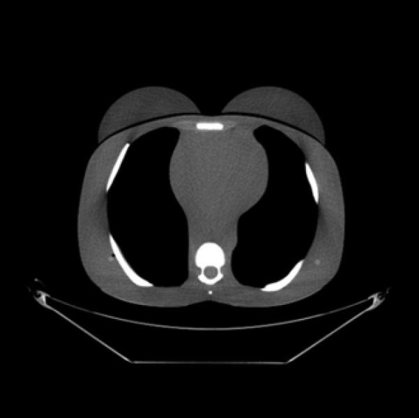
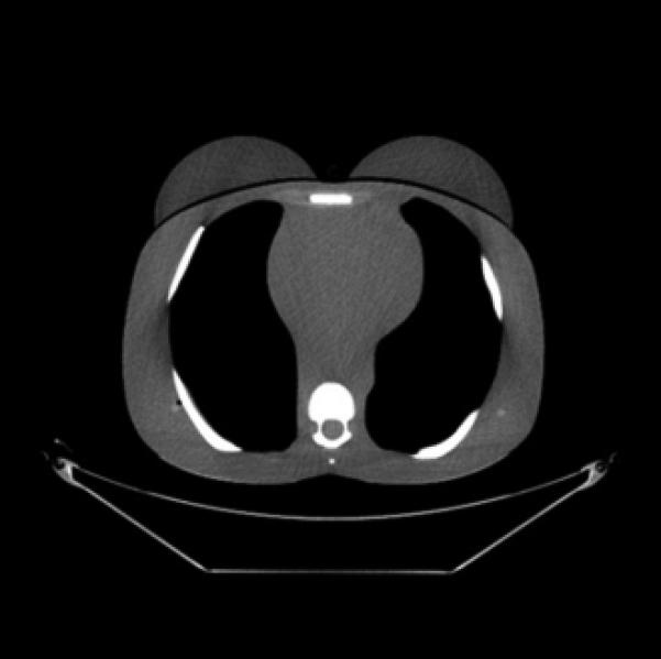
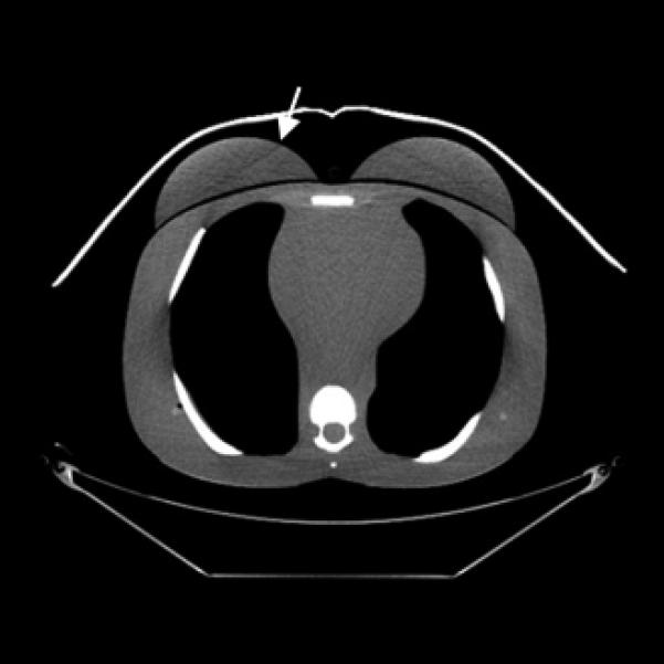
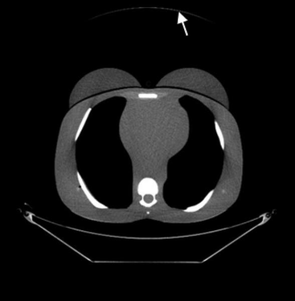
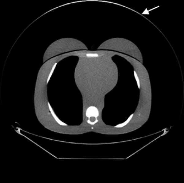
CT images (mediastinum window level) of the (female) adult phantom scanned (using the clinical adult chest protocol listed in Table 1) on a GE Discovery CT750 HD scanner.
A, Unshielded (without ASiR).
B, Unshielded (with ASiR).
C, Bismuth breast shielding. Note the artifact (arrow) caused by the breast shield.
D, Copper foil beam filtration. Note the artifact (arrow) caused by the copper foil.
E, Lead foil beam filtration. Note the artifact (arrow) caused by the lead foil.
Table 4 lists the CT numbers, along with the noise in the CT images, according to the ROI location, phantom, and scanner. The mean shift in CT numbers (relative to unshielded scans) across the four ROIs, three phantoms, and two scanners was 18.3, 10.3, and 32.4 HU for scans with bismuth breast shields, copper foil filtration, and lead foil filtration, respectively. The mean percentage of increase in noise (across all ROIs, phantoms, and scanners) compared to the noise in unshielded scans was 23%, 8.2%, and 32% for the breast shields, copper foil, and lead foil, respectively. Across the two anterior ROIs (left breast and sternum), the mean shift in CT numbers was 31.4, 11.6, and 38.5 HU for scans with bismuth breast shields, copper foil filtration, and lead foil filtration, respectively; the corresponding mean percentage of increase in noise was 36%, 7.7%, and 39%, respectively. Thus, the overall (and particularly the anterior) CT numbers and noise were relatively less affected by the copper foil filtration than by the bismuth breast shielding or the lead foil filtration. Furthermore, for the most part, the magnitude of the shifts in CT numbers caused by the presence of the copper foil filtration was within one standard deviation (i.e., the noise level) of the CT number measured in the ROI of the corresponding unshielded scans. The mean shift in the CT numbers in (unshielded) scans with 40% ASiR compared to (unshielded) scans without ASiR was less than 1 HU, and the images reconstructed with 40% ASiR had 6% less noise on average than the images reconstructed without ASiR even though they were acquired at a higher dose.
TABLE 4.
Computed Tomography Numbersa and Noiseb Measured from the Anthropomorphic Phantom Images for each Region of Interestc
| ROI location | Filtration or Shielding | GE LightSpeed VCT Scannera | GE Discovery CT750 HD Scannerb | ||||
|---|---|---|---|---|---|---|---|
| 5-Year-Old Phantom | 10-Year-Old Phantom | Adult Phantom | 5-Year-Old Phantom | 10-Year-Old Phantom | Adult Phantom | ||
| Sternum | Unshielded (TCM w/o ASiR) | 2.13 (17.5) | 13.5 (17.4) | 32.4 (19.4) | 4.84 (16.2) | 18.6 (15.1) | 37.9 (19.7) |
| Unshielded (TCM w/ ASiR) | N/A | N/A | N/A | 4.11 (16.2) | 18.0 (13.0) | 42.3 (20.3) | |
| Bismuth breast shield | 24.0 (23.6) | 30.7 (21.4) | 58.1 (15.1) | 29.1 (16.6) | 32.3 (20.1) | 67.3 (17.7) | |
| Copper foil | 6.03 (17.6) | 17.5 (18.2) | 41.3 (16.8) | 15.1 (19.8) | 15.9 (15.1) | 54.1 (17.4) | |
| Lead foil | 34.8 (28.3) | 49.5 (27.1) | 75.8 (26.2) | 38.7 (22.4) | 35.6 (17.7) | 70.1 (20.0) | |
| Left breast | Unshielded (TCM w/o ASiR) | −5.02 (14.0) | −15.4 (15.7) | −42.2 (16.0) | 0.55 (14.8) | −69.9 (12.6) | −31.8 (13.4) |
| Unshielded (TCM w/ ASiR) | N/A | N/A | N/A | −0.06 (14.1) | −72.9 (11.3) | −32.9 (14.2) | |
| Bismuth breast shield | 13.2 (22.9) | 17.7 (24.2) | 27.1 (26.2) | 38.7 (23.7) | −39.8 (19.1) | 23.9 (24.5) | |
| Copper foil | 3.27 (20.5) | −1.33 (16.6) | −17.2 (17.4) | 7.34 (13.6) | −44.4 (14.5) | −13.2 (16.3) | |
| Lead foil | 21.0 (24.8) | 22.6 (19.7) | 29.8 (24.3) | 26.3 (20) | −24.9 (17.2) | 27.8 (18.4) | |
| Posterior soft tissue | Unshielded (TCM w/o ASiR) | 2.21 (20.5) | 10.9 (21.2) | −2.26 (20.5) | −2.68 (20.4) | 10.3 (22.0) | 0.46 (17.8) |
| Unshielded (TCM w/ ASiR) | N/A | N/A | N/A | −2.74 (19.8) | 9.33 (16.7) | −0.19 (14.4) | |
| Bismuth breast shield | 2.87 (24.9) | 11.7 (26.2) | −0.44 (20.1) | 1.17 (22.8) | 12.4 (20.0) | 2.26 (16.7) | |
| Copper foil | −786 (13.6) | 11.1 (21.5) | 3.69 (22.6) | −779 (13.8) | 9.69 (25.3) | 8.64 (18.6) | |
| Lead foil | −757 (18.7) | 35.0 (24.1) | 10.9 (22.2) | −754 (19.6) | 32.9 (27.1) | 16.6 (17.9) | |
| Lung | Unshielded (TCM w/o ASiR) | −798 (13.1) | −811 (13.3) | −791.5 (10.0) | −795 (13.7) | −805 (13.2) | −787 (10.0) |
| Unshielded (TCM w/ ASiR) | N/A | N/A | N/A | −793 (12.9) | −806 (12.1) | −786 (10.4) | |
| Bismuth breast shield | −786 (14.3) | −799 (16.3) | −786 (12.4) | −786 (13.4) | −798 (12.7) | −782 (11.5) | |
| Copper foil | −786 (13.6) | −795 (14.4) | −779 (12.8) | −779 (13.8) | −793 (13.6) | −774 (11.6) | |
| Lead foil | −757 (18.7) | −777 (18.8) | −766 (14.1) | −754 (19.6) | −774 (15.5) | −761 (13.2) | |
Note: ROI = region of interest, TCM = tube current modulation, ASiR = adaptive statistical iterative reconstruction.
The mean CT number is given Hounsfield units
The noise (i.e., standard deviation of the CT numbers; in Hounsfield units) is shown in parentheses below the mean CT number.
The specific location of each region of interest can be seen in Figure 3.
Discussion
In this study, we found that copper foil beam filtration reduced radiation doses at the surface of anthropomorphic phantoms by between 28% and 66% while only increasing the CT image noise (on average) by 8.2%. These dose reductions were roughly the same as those achieved from using in-plane bismuth breast shielding; however, by using copper foil beam filtration, streaks artifacts within the anatomy were eliminated and there was a much smaller impact on image noise and CT number shift (particularly in the anterior anatomy). Although lead foil beam filtration resulted in the greatest reductions in entrance dose, it also had the greatest impact on CT number and image noise compared to unshielded scans. To the best of our knowledge, no prior study has evaluated the effect of partial arc filtration of the primary CT x-ray beam.
The current study had several limitations. For instance, both the copper foil tape and the lead foil tape used in this study had an acrylic adhesive and a paper liner. Although this did not affect proof of concept, the specific dose reductions may have differed slightly if pure lead and copper (i.e., without an adhesive) had been used. Another limitation of the current study was that we did not determine dose reductions relative to scans with a static tube current and thus we did not specifically quantify the effect of TCM alone on dose reduction. Also, while we assessed several measures of image quality in this study (i.e., image noise, CT number shift, and streak artifacts), we did not perform a full evaluation of how image quality is affected by partial arc beam filtration. Furthermore, we assessed images from anthropomorphic phantoms rather than patients. This is particularly important to consider since this technology has a beam-hardening effect, which could potentially impair diagnostic image quality in favor of dose reduction. In the future, a reader study could be performed to determine this. Finally, clinical implementation of partial arc beam filtration as described in this study would present several practical limitations. First, the foil would have to be placed after the scout had been acquired if the scanning protocol dictated the use of TCM, which would be cumbersome with the patient lying on the scanner table. Second, most scans cover anatomy beyond the breasts and leaving the foil in place over the entire scan extent could result in detrimental image degradation in other regions. While this initial study was conducted for proof of concept, in order for clinical utility of partial arc beam filtration to be achieved, it would need to be fully incorporated into CT scanner design.
Despite the limitations of this study, our findings indicate that partial arc beam filtration would likely improve upon a number of the drawbacks typically associated with X-Care (e.g., increased spine dose) and in-plane bismuth breast shields (e.g., streak artifacts within the anatomy). Additionally, several of these limitations could be further improved upon by incorporating this technology into scanner design, such as issues with timing of shield placement relative to scout acquisition. In order to incorporate partial arc beam filtration into CT scanners, a dynamic filter (similar to a camera shutter) made of a dense material (e.g., lead, copper, etc.) could be quickly placed over the output port of the x-ray beam at angular positions of the x-ray tube corresponding to direct exposure of a patient's breast tissue (the location of which could be determined using the patient's scout). While partial arc beam filtration may cause a small shift in the CT numbers (the shifts we observed due to the copper foil beam filtration were generally less than those caused by bismuth breast shields, and many radiologists are accustomed to interpreting CT images that have been affected by breast shields), if incorporated into CT scanners, the CT number shifts would likely be smaller than those reported because only the entrance beam would be filtered, whereas both the entrance and exit beam were filtered in this study due to physical limitations. Furthermore, shifts in CT numbers could potentially be reduced by implementing correction algorithms or by using less attenuating beam filtration (although this would also result in less dose reduction). Although implementation of partial arc beam filtration would require some design changes to CT scanners, the authors do not believe that the required changes would be substantial enough to limit this technology's usefulness in the future.
Before partial arc beam filtration can be incorporated into CT scanners, further analysis is needed to evaluate the effect of this technology on image quality in patient scans. Additionally, Monte Carlo modeling could be employed to estimate absorbed breast dose in patients because anthropomorphic phantoms may not accurately represent modern patient sizes and also cannot account for the broad range in the amount and distribution of breast tissue across patients (even in patients of similar size and age) [12]. Finally, the use of partial arc beam filtration for other superficial radiosensitive organs such as the eyes, thyroid, and testes could be considered in the future.
Conclusion
In this study, we found that copper foil beam filtration reduced entrance breast dose by 28 – 66% (compared to scans without any added filtration or shielding) across three sizes of anthropomorphic phantoms. While this was roughly equivalent to the dose reduction we observed from using in-plane bismuth breast shielding, copper foil beam filtration was shown to have a smaller impact on CT number shift and image noise (10.3 mean HU shift and 8.2% mean increase in noise for copper foil beam filtration versus 18.3 mean HU shift and 23% mean increase in noise for in-plane bismuth breast shielding). This was particularly true when considering these characteristics in the phantoms’ anterior region. Additionally, no streak artifacts were observed within the phantom anatomy in the scans with copper foil beam filtration unlike those with breast shielding. This study supports the development of new strategies to reduce CT radiation dose to the breast tissue, as well as the combination of multiple dose-reduction strategies (e.g., tube current modulation and iterative reconstruction) to maximize CT dose reduction while maintaining image integrity.
Acknowledgments
This research was supported by NIH grants CA016672 and R01-EB0048989.
REFERENCES
- 1.ICRP The 2007 Recommendations of the International Commission on Radiological Protection. ICRP publication 103. Ann ICRP. 2007;37:1–332. doi: 10.1016/j.icrp.2007.10.003. [DOI] [PubMed] [Google Scholar]
- 2.Vollmar SV, Kalender WA. Reduction of dose to the female breast in thoracic CT: a comparison of standard-protocol, bismuth-shielded, partial and tube-current-modulated CT examinations. Eur Radiol. 2008;18:1674–1682. doi: 10.1007/s00330-008-0934-9. [DOI] [PubMed] [Google Scholar]
- 3.Hopper KD. Orbital, thyroid, and breast superficial radiation shielding for patients undergoing diagnostic CT. Semin Ultrasound CT MR. 2002;23:423–427. doi: 10.1016/s0887-2171(02)90013-2. [DOI] [PubMed] [Google Scholar]
- 4.Research Fuels Debate over Bismuth Breast Shields. RSNA News. 2011 [Google Scholar]
- 5.Geleijns J, Wang J, McCollough C. The use of breast shielding for dose reduction in pediatric CT: arguments against the proposition. Pediatr Radiol. 2010;40:1744–1747. doi: 10.1007/s00247-010-1808-2. [DOI] [PubMed] [Google Scholar]
- 6.Wang J, Duan X, Christner JA, Leng S, Yu L, McCollough CH. Radiation dose reduction to the breast in thoracic CT: Comparison of bismuth shielding, organ-based tube current modulation, and use of a globally decreased tube current. Med Phys. 2011;38:6084–6092. doi: 10.1118/1.3651489. [DOI] [PubMed] [Google Scholar]
- 7.Kalra MK, Dang P, Singh S, Saini S, Shepard JA. In-plane shielding for CT: effect of off-centering, automatic exposure control and shield-to-surface distance. Korean J Radiol. 2009;10:156–163. doi: 10.3348/kjr.2009.10.2.156. [DOI] [PMC free article] [PubMed] [Google Scholar]
- 8.Kruger RL, McCollough CH, Zink FE. Measurement of half-value layer in x-ray CT: A comparison of two noninvasive techniques. Med Phys. 2000;27:1915–1919. doi: 10.1118/1.1287440. [DOI] [PubMed] [Google Scholar]
- 9.LightSpeed VCT Technical Rerefence Manual, 5116422-100 Rev. 5. GE Healthcare; 2006. [Google Scholar]
- 10.Discovery CT750 HD Feature Overview, Direction5367993-1EN Rev. 1, GE Medical Systems. 2009 [Google Scholar]
- 11.The Measurement, Reporting and Management of Radiation Dose in CT. American Association of Physicists in Medicine; College Park, MD: 2008. [Google Scholar]
- 12.Kleinman PL, Strauss KJ, Zurakowski D, Buckley KS, Taylor GA. Patient size measured on CT images as a function of age at a tertiary care children's hospital. Am J Roentgenol. 2010;194:1611–1619. doi: 10.2214/AJR.09.3771. [DOI] [PubMed] [Google Scholar]


