

Abstract
Microfluidic approaches for controlled generation of colloidal clusters, e.g., via encapsulation of colloidal particles in droplets, have been used for the synthesis of functional materials including drug delivery carriers. Most of the studies, however, use a low concentration of an original colloidal suspension (< 10 wt%). Here we demonstrate microfluidic approaches for directly making droplets with moderate (10–25 wt%) and high (> 60 wt%) particle concentrations. Three types of microfluidic devices, PDMS flow-focusing, PDMS T-junction, and microcapillary devices, are investigated for direct encapsulation of a high concentration of polystyrene (PS) nanoparticles in droplets. In particular, it is shown that PDMS devices fabricated by soft lithography can generate droplets from a 25 wt% PS suspension, whereas microcapillary devices made from glass capillary tubes are able to produce droplets from a 67 wt% PS nanoparticle suspension. When the PS concentration is between 0.6 and 25 wt%, the size of the droplets is found to change with the oil-to-water flow rate ratio and is independent of the concentration of particles in the initial suspensions. Drop sizes from ~12 to 40 μm are made using flow rate ratios Qoil/Qwater from 20 to 1, respectively, with either of the PDMS devices. However, clogging occurs in PDMS devices at high PS concentrations (> 25 wt%) arising from interactions between the PS colloids and the surface of PDMS devices. Glass microcapillary devices, on the other hand, are resistant to clogging and can produce droplets continuously even when the concentration of PS nanoparticles reaches 67 wt%. We believe that our findings indicate useful approaches and guidelines for the controlled generation of emulsions of microparticles that are filled with a high loading of nanoparticles and which are useful for drug delivery applications.
Keywords: Microfluidic, colloidal droplets, nanoparticles, encapsulation
INTRODUCTION
Colloidal particles are important components in food products, cosmetics, coatings, and drug delivery. Consequently, the controlled synthesis and assembly of colloidal particles is of a broad interest.1–3 Microfluidic technologies make possible the manipulation of fluids and objects at the microscale and have been demonstrated as effective methods to produce colloidal clusters with desired structures and functions.4,5 For example, microfluidic encapsulation of colloidal particles in droplets has been used to synthesize colloidal photonic crystals,6,7 colloidosomes (hollow capsules with packed colloidal particles as the shell),8,9 and to explore the self-organizing processes of colloids in a confined geometry.10 Furthermore, colloidal emulsions fabricated by microfluidic approaches have a narrow size distribution and controlled shapes and permeability, which make them attractive candidates as materials for targeted delivery/controlled release.11
We are interested in the fabrication of microparticles from emulsions that contain functional nanoparticles for drug delivery, e.g., treatment of lung cancers.12 In this scenario, microparticles with sizes larger than that of red blood cells (i.e. ~10–40 microns) are injected into the venous circulation and when they pass to the lungs can mechanically lodge in the lung microcapillary bed. A microparticle encapsulates drug nanoparticles, therefore, very high loadings of the drug nanoparticles are required to deliver high levels of drugs while causing as little disruption as possible to the lung function. Kutscher et al. have shown that 6 micrometer diameter particles with a high modulus transiently lodge in the lungs and then are cleared over seven days.13 Further, they showed that much softer but poorly characterized gel particles with sizes on the order of 50 microns were transiently captured and cleared in the same time frame.14 Our ultimate goal is to produce microparticles with 1) high loadings of drug nanoparticles, 2) controlled sizes at tens of micrometer diameter using microfluidics, and 3) to control the modulus of the particles by post-polymerization of a polymeric macromer in the colloidal droplets. The goal of this paper is to explore the formation of droplets in this size range by microfluidics and to study the effect of a high colloid loading on the formation of drops. The gel polymerization and tuning of the modulus will be discussed in future reports.
Reported strategies for microfluidic encapsulation of colloidal particles in droplets, however, have used colloidal suspensions with low concentrations of particles, e.g., less than 10 wt%.5,8,9 Although increasing the concentration of colloidal particles in droplets can be achieved by evaporating the colloidal droplets,7 avoidance of this second step would be preferred. In the current study, polystyrene (PS) nanoparticles were selected as a model colloid system. Specifically, we choose a colloid that is relatively unstable to investigate a “worst case” for creating highly loaded emulsion drops; that is, the 500 nm diameter PS colloid we use has a bare hydrophobic surface and is stabilized only by electrostatic repulsion, which makes it prone to aggregation at high shear rates and concentrations. Three types of microfluidic devices, e.g., a PDMS T-junction geometry, a PDMS flow-focusing geometry, and a glass co-axial microcapillary cell, are used to investigate the direct encapsulation of a high concentration of nanoparticles in micron-sized droplets (Figure 1).
Figure 1.
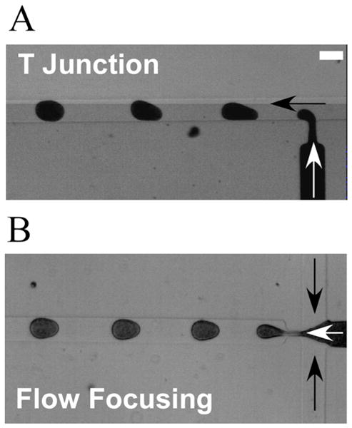
Microfluidic geometries for the generation of aqueous droplets from polystyrene nanoparticle suspensions. (A) Image of the generation of droplets in a T-junction microfluidic device. (B) Image of the generation of droplets in a flow-focusing microfluidic device. Black arrows and white arrows indicate, respectively, the flow directions of the oil and aqueous phase. The height and the width of the channel are 20 and 100 μm, respectively; the width of orifice is 20 μm. Scale bar: 100 μm.
EXPERIMENTAL
A detailed description of the materials, fabrication of microfluidic channels and experimental setup can be found in the Supporting Information (SI). Briefly, PDMS and microcapillary microfluidic channels are fabricated using standard soft photolithography techniques and glass capillary tubes, respectively. PS nanoparticle suspensions and PDMS oil (viscosity 10 cSt, Aldrich) are used, respectively, as the aqueous phase and oil phase. A high-speed camera (V9, phantom) connected to a microscope is used to observe the generation of drops with encapsulated nanoparticles. For the purpose of developing drug delivery systems, we prefer less surfactant so as to avoid immune responses when the particles are injected into the body. Therefore we did not use any surfactant throughout our studies. All the experiments are conducted at room temperature.
RESULTS AND DISCUSSION
We demonstrate that PDMS microfluidic devices (flow-focusing and T-junction) made by soft lithography can generate droplets from 0.6–25 wt% aqueous nanoparticle suspensions using a continuous oil phase. The size of the droplets decreases with an increase of the oil-to-water flow rate ratio (Figure 2), which is consistent with the literature on the generation of droplets using PDMS microfluidics.15,16 However, an unsteady fluctuation in particle concentration in the drops is observed for the flow-focusing device, although the drop size is constant. This instability is observed less frequently for the T-junction devices. On the other hand, microcapillary devices made from glass capillary tubes can produce droplets from a 67 wt% nanoparticle suspension without clogging. The results suggest that at particle concentrations as high as 25 wt% PDMS microfluidic devices can be used for direct encapsulation of particles in droplets. However, at higher concentrations of particle suspensions, clogging jeopardizes the performance of PDMS devices and the microcapillary approach is a promising alternative.
Figure 2.
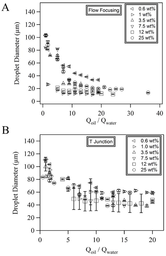
Control of the size of colloidal droplets. Dependence of the droplet diameter on the oil-to-water flow rate ratio at various weight percentages of PS in (A) flow-focusing and (B) T-junction microfluidic devices.
We also notice that the concentration of particles in the initial PS nanoparticle suspensions does not affect significantly the sizes of droplets over the range of concentrations between 0–25 wt%. Because it is known that the viscosity of a colloidal suspension depends on the volume fraction of particles,17 and the viscosity ratio between the disperse and continuous phases affects the generation of droplets in microfluidic devices,18–20 rheological measurements were conducted in a cone-plate rheometer to measure the viscosities of the suspensions as a function of concentration and shear rate (Figure 3). The results show that at low shear rates (from 10−2 - 10 s−1) the viscosity of the nanoparticle suspension (0.6–25 wt% nanoparticles) is 1000 fold higher than the high shear rate Newtonian viscosity of the dispersion. This behavior is a characteristic of an electrostatically stabilized dispersion with strong repulsions.21,22 When the shear rate is higher than 100 s−1, the viscosity of the nanoparticle suspension decreases towards a high shear rate Newtonian viscosity plateau, η∞ ≈ 0.9–1.4 mPa·s, which is close to the viscosity of water. The η∞ value for the 25 wt% dispersion is 1.4 mPa.s, which is consistent with η∞ measurements of latex dispersions in this concentration range.23–25 At 10 s−1 there is a local maximum in the viscosity of the most highly filled, i.e. 25 wt%, dispersion. This transient dilatancy is observed for dispersions in the solids concentration range where shear forces are large enough to cause weak aggregation but are broken up at higher stress levels.24,26,27 The upturn in the data at shear rates of 104 s−1 is due to sample inertia at high rotation rates and not dilatancy. Since the results in Figure 3 show that the viscosity does not change substantially with PS concentration, the volume fraction of colloidal particles in the suspension does not have a dominant effect on the generation of colloidal droplets. Because the average shear rate in our microfluidic experiment is between 400 and 8000 s−1, the nanoparticle suspensions behave as low viscosity Newtonian fluids during drop breakup.
Figure 3.
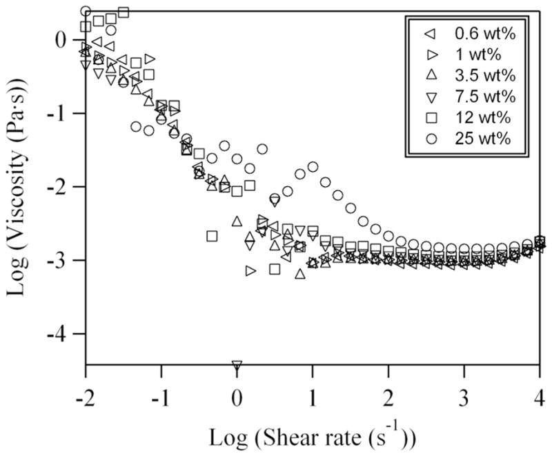
Shear-rate dependence of the viscosity of the polystyrene nanoparticle suspensions containing various weight percentages of nanoparticles. The rise in viscosity at low shear rates and high shear rate Newtonian viscosity, η∞ are characteristic of dispersions with strong electrostatic repulsions. The peak in the viscosity for the 25 wt% dispersion occurs due to shear-induced transient dilatancy. At this nanoparticle concentration the aggregates are dispersed at higher stress levels and the viscosity again becomes Newtonian (the high shear rate limit is nearly the viscosity of water).
During the generation of colloidal droplets in a flow-focusing device at the highest PS loading, transient jamming of nanoparticles near the orifice of the channel was observed, which can trigger a frequent release of droplets with jammed nanoparticles, as shown in Figure 4A. In our experiments, the size variation of drops is relatively small. However, at higher loadings transient jamming near the orifice, with the intermittent release of aggregated particle clusters can cause fluctuations in the particle densities in droplets. Therefore, due to the jamming-induced concentration fluctuations, it is not always true that a large drop contains more particles.
Figure 4.

Concentration of the PS nanoparticles in droplets. (A) Image of the generation of a droplet (the second droplet downstream of the orifice) with a high concentration of PS particles. Black and white arrows indicate the flow directions of the oil and aqueous phase, respectively. Scale bar: 100 μm. (B) Bright-field image of an aqueous droplet generated by a T-junction microfluidic device. During the generation of the drop, there is no large aggregation of particles in the drop. 1 wt% PS suspension with a given amount (correlated by the image of the control sample) of fluorescent dye-doped PS particles is used as the aqueous phase. (C) Confocal fluorescence image of the same droplet shown in Figure 4B. (D) Number of fluorescent dye-doped PS particles per area in bulk PS suspension (control) in droplets generated by a T-junction device, and in droplets generated by a flow-focusing device. The drops contain aggregation of particle clusters when they are generated in either the T-junction or flow-focusing device. Error bar is the standard deviation of 5–7 samples.
To quantitate the concentration of particles in the droplets, fluorescent tracer nanoparticles were added to the initial suspension to investigate the variations of particle concentration in the droplets. The tracer nanoparticles are the same as the nanoparticles used in the suspension except that they are doped with fluorescent dyes (see SI). Therefore, tracer nanoparticles are well dispersed in the initial PS suspension and do not introduce confounding effects due to differences in size, density, or surface properties. Figures 4B and 4C show typical bright-field and fluorescence images of a PS colloidal droplet containing fluorescent tracer nanoparticles for the case where no large aggregated particles were observed. For the drops generated with aggregated particles, we analyze the particle concentration by counting the number of fluorescence particles per unit area (pixel) from confocal fluorescence images (Figure 4D and SI Figure 2). The results show that the particle concentration in droplets generated by flow-focusing devices is higher compared to the original PS suspension and the droplets generated by a T-junction. In addition, we also observed that jamming occurred more frequently in the flow-focusing devices.
We made careful observations of the sequence of events leading to jamming, with visualization in different focal planes of the channel, and found that most of the jamming observed in the PDMS devices started from the attachment of particles onto the bottom surface of the microfluidic channel near the orifice. Although the mechanism of jamming remains unclear, we believe that the flow pattern, such as the recirculation flow near by the orifice in the flow-focusing PDMS device may play a role. Therefore, we fabricated the glass coaxial microcapillary device to test the sensitivity of this geometry to jamming. Figure 5A shows the schematic of the microcapillary device we used in the experiment. We found that these microcapillary devices could continuously generate droplets from a 67 wt% of PS suspension, which is more than twice the particle concentration achievable with the PDMS microfluidic configurations (Figure 5B and 5C), and is near the close-packed limit for the nanoparticles. At these extraordinarily high volume fractions the polystyrene nanoparticles form dispersions with weak yield stresses, but which are shear thinning. The result is that the microcapillary geometry can form micro-droplets, but the disperse phase has a yield stress and surface tension that is not large enough to deform the droplets to a spherical shape once they are coalesced (Figure 5C). Further characterization of the colloidal droplets using SEM shows highly packed PS nanoparticles after the droplets are dried in the SEM chamber (Figure 5D and 5E). This ability to form non-spherical drops using fluids with weak yield stresses may provide an attractive route to form non-spherical particles using microfluidics. For example, non-spherical particles have shown unique properties in their ability to deliver drugs and optimize cell uptake.28–30 This observation is certainly an important area for future investigation.
Figure 5.

Generation of droplets with a high loading of PS particles. (A) Schematic illustration of the microcapillary device. (B) Image of generation of droplets with a high loading of PS particles by using a microcapillary device. An initial PS suspension of 67 wt% is used as the aqueous phase. Scale bar: 500 μm. (C) Bright-field image of colloidal droplets generated by a microcapillary device. The non-spherical drops are generated from coalescence of two or more spherical drops and are stable for at least hours. Scale bar: 500 μm. (D) Scanning electron microscope image (SEM) of a colloidal droplet with a high loading of PS particles. (E) High magnification of the SEM image on the surface of the colloidal droplet shown in Figure 5D.
CONCLUSIONS
In conclusion, we have demonstrated three types of microfluidic devices, PDMS flow-focusing, PDMS T-junction, and glass microcapillary microfluidic devices, for generation of droplets highly loaded with solid nanoparticles. Using these geometries we have addressed the question of what is the highest solids loading that can be achieved with droplet microfluidics. The PDMS microfluidic devices can generate droplets from a 25 wt% of PS suspension, whereas the microcapillary devices produce droplets from suspensions with particle loadings as high as 67 wt%. When the particle concentration in the initial PS suspensions is between 0.6 and 25 wt%, the suspension flows as a Newtonian fluid and the concentration of particles does not affect the generation of droplets. Above 25 wt% of PS particles, clogging occurs most frequently at the place where the droplets were generated in PDMS devices and becomes the major problem. Glass microcapillary devices function even with 67 wt% PS suspension without any clogging problems and, therefore, are promising alternatives for the generation of droplets with high loadings of nanoparticles. We hypothesize that the higher concentrations achievable with the glass capillary device are due to the hydrophilicity of the glass interface and the absence of abrupt changes in flow streamlines – both of which would reduce particle aggregation. The observation that non-spherical drops can be formed from fluids with weak yield stresses is an important new observation, since much recent work has focused on unique phenomena observed with non-spherical particles. We believe our results for the generation of a high loading of nanoparticles in droplets by using different microfluidic approaches will provide useful guidelines for the direct fabrication of colloidsome and colloidal-based drug delivery materials.
Supplementary Material
Acknowledgments
We thank Jiang Li and Haosheng Chen for help with the microcapillary devices. We are grateful for financial support from NIH (1R01CA155061-01) This material is based upon work supported by the NSF Graduate Research Fellowship under Grant No. DGE-0646086.
Footnotes
Supporting Information Available. Materials, fabrication of microfluidic channels, experimental setup, light scattering and SEM results of PS particles, confocal images of fluorescent PS particles in bulk suspension and droplets. This information is available free of charge via the Internet at http://pubs.acs.org/.
References
- 1.Russel WB, Saville DA, Schowalter WR. Colloidal Dispersions. Cambridge University Press; Cambridge: 1989. [Google Scholar]
- 2.Xia Y, Gates B, Yin Y, Lu Y. Monodispersed Colloidal Spheres: Old Materials with New Applications. Adv Mater. 2000;12:693–713. [Google Scholar]
- 3.Li F, Josephson DP, Stein A. Colloidal assembly: the road from particles to colloidal molecules and crystals. Angew Chem Int Ed. 2011;50:360–388. doi: 10.1002/anie.201001451. [DOI] [PubMed] [Google Scholar]
- 4.Studart AR, Studer J, Xu L, Yoon K, Shum HC, Weitz DA. Hierarchical porous materials made by drying complex suspensions. Langmuir. 2011;27:955–964. doi: 10.1021/la103995g. [DOI] [PubMed] [Google Scholar]
- 5.Yi GR, Thorsen T, Manoharan VN, Hwang MJ, Jeon SJ, Pine DJ, Quake SR, Yang SM. Generation of uniform colloidal assemblies in soft microfluidic devices. Adv Mater. 2003;15:1300–1304. [Google Scholar]
- 6.Lee SK, Yi GR, Yang SM. High-speed fabrication of patterned colloidal photonic structures in centrifugal microfluidic chips. Lab on a Chip. 2006;6:1171–1177. doi: 10.1039/b606448e. [DOI] [PubMed] [Google Scholar]
- 7.Yi GR, Jeon SJ, Thorsen T, Manoharan VN, Quake SR, Pine DJ, Yang SM. Generation of uniform photonic balls by template-assisted colloidal crystallization. Synthetic Metals. 2003;139:803–806. [Google Scholar]
- 8.Sander JS, Studart AR. Monodisperse functional colloidosomes with tailored nanoparticle shells. Langmuir. 2011;27:3301–3307. doi: 10.1021/la1035344. [DOI] [PubMed] [Google Scholar]
- 9.Shah RK, Kim JW, Weitz DA. Monodisperse stimuli-responsive colloidosomes by self-Assembly of microgels in droplets. Langmuir. 2010;26:1561–1565. doi: 10.1021/la9041327. [DOI] [PubMed] [Google Scholar]
- 10.Manoharan VN, Elsesser MT, Pine DJ. Dense packing and symmetry in small clusters of microspheres. Science. 2003;301:483–487. doi: 10.1126/science.1086189. [DOI] [PubMed] [Google Scholar]
- 11.Rosenberg RT, Dan N. Self-Assembly of colloidosome shells on drug-containing hydrogels. J Biomater Nanobiotech. 2011;2:1–7. [Google Scholar]
- 12.Prud’homme RK, Sinko PJ, Stone HA, Pinkerton NM, Shi L, Wan J, Ibrahim S, Gao D. Lung targeting dual drug delivery system. 20110268803 US Patent. 2011
- 13.Kutscher HL, Chao P, Deshmukh M, Singh Y, Hu P, Joseph LB, Reimer DC, Stein S, Laskin DL, Sinko PJ. Threshold size for optimal passive pulmonary targeting and retention of rigid microparticles in rats. J Control Release. 2010;143:31–37. doi: 10.1016/j.jconrel.2009.12.019. [DOI] [PMC free article] [PubMed] [Google Scholar]
- 14.Chao P, Deshmukh M, Kutscher HL, Gao D, Rajan SS, Hu P, Laskin DL, Stein S, Sinko PJ. Pulmonary targeting microparticulate camptothecin delivery system: anticancer evaluation in a rat orthotopic lung cancer model. Anti-Cancer Drugs. 2010;21:65–76. doi: 10.1097/CAD.0b013e328332a322. [DOI] [PMC free article] [PubMed] [Google Scholar]
- 15.Teh SY, Lin R, Hungb LH, Lee AP. Droplet microfluidics. Lab on a Chip. 2008;8:198–220. doi: 10.1039/b715524g. [DOI] [PubMed] [Google Scholar]
- 16.Wan J, Bick A, Sullivan M, Stone HA. Controllable microfluidic production of microbubbles in water-in-oil emulsions and the formation of porous microparticles. Adv Mater. 2008;20:3314–3318. [Google Scholar]
- 17.Mewis J, Wagner NJ. Colloidal Suspension Rheology. Cambridge University Press; 2011. [Google Scholar]
- 18.Nie Z, Seo M, Xu S, Lewis PC, Mok M, Kumacheva E, Whitesides GM, Garstecki P, Stone HA. Emulsification in a microfluidic flow-focusing device: effect of the viscosities of the liquids. Microfluid Nanofluid. 2008;5:585–594. [Google Scholar]
- 19.van Dijke K, Kobayashi I, Schroen K, Uemura K, Nakajima M, Boom R. Effect of viscosities of dispersed and continuous phases in microchannel oil-in-water emulsification. Microfluid Nanofluid. 2010;9:77–85. [Google Scholar]
- 20.Vladisavljevic GT, Kobayashi I, Nakajima M. Effect of dispersed phase viscosity on maximum droplet generation frequency in microchannel emulsification using asymmetric straight-through channels. Microfluid Nanofluid. 2011;10:1199–1209. [Google Scholar]
- 21.Buscall R. Effect of long-range repulsive forces on the viscosity of concentrated latices: comparison of experimental data with an effective hard-sphere model. J Chem Soc Faraday Transactions. 1991;87:1365–1370. [Google Scholar]
- 22.Wang YL. Electroviscous effects of concentrated polystyrene latexes. J Colloid Interface Sci. 1970;32:633–641. [Google Scholar]
- 23.Horn FM, Richtering W, Bergenholtz J, Willenbacher N, Wagner NJ. Hydrodynamic and colloidal interactions in concentrated charge-stabilized polymer dispersions. J Colloid Interface Sci. 2000;225:166–178. doi: 10.1006/jcis.1999.6705. [DOI] [PubMed] [Google Scholar]
- 24.Wagner NJ, Brady JF. Shear thickening in colloidal dispersions. Physics Today. 2009:27–32. [Google Scholar]
- 25.Wildemuth CR, Williams MC. Viscosity of suspensions modeled with a shear-dependent maximum packing fraction. Rheologica Acta. 1984;23:627–635. [Google Scholar]
- 26.Laun HM, Bung R, Hess S, Loose W, Hess O, Hahn K, Hadicke E, Hingmann R, Schmidt F, Lindner P. Rheological and small-angle neutron-scattering investigation of shear-induced particle structures of concentrated polymer dispersions submitted to plane Poiseuille and couette-flow. J Rheology. 1992;36:743–788. [Google Scholar]
- 27.Barnes HA. Shear-thickening (dilatancy) in suspensions of non-aggregating solid particles dispersed in Newtonian liquids. J Rheology. 1989;33:329–366. [Google Scholar]
- 28.Champion JA, Katare YK, Mitragotri S. Particle shape: a new design parameter for micro- and nanoscale drug delivery carriers. J Control Release. 2007;121:3–9. doi: 10.1016/j.jconrel.2007.03.022. [DOI] [PMC free article] [PubMed] [Google Scholar]
- 29.Christian DA, Cai S, Garbuzenko OB, Harada T, Zajac AL, Minko T, Discher DE. Flexible filaments for in vivo imaging and delivery: persistent circulation of filomicelles opens the dosage window for sustained tumor shrinkage. Molecular Pharmaceutics. 2009;6:1343–1352. doi: 10.1021/mp900022m. [DOI] [PMC free article] [PubMed] [Google Scholar]
- 30.Geng Y, Dalhaimer P, Cai SS, Tsai R, Tewari M, Minko T, Discher DE. Shape effects of filaments versus spherical particles in flow and drug delivery. Nat Nanotech. 2007;2:249–255. doi: 10.1038/nnano.2007.70. [DOI] [PMC free article] [PubMed] [Google Scholar]
Associated Data
This section collects any data citations, data availability statements, or supplementary materials included in this article.