Abstract
Recently, scaffolds for tissue regeneration purposes have looked to utilize nanoscale features in an effort to reap the cellular benefits of scaffold features resembling extracellular matrix (ECM) components. However, one complication surrounding electrospun nanofibers is limited cellular infiltration. One method to ameliorate this negative effect is by incorporating nanofibers into microfibrous scaffolds. This study shows that it is feasible to fabricate electrospun scaffolds containing two differently scaled fibers interspersed evenly throughout the entire construct as well as scaffolds containing fibers composed of two discreet materials, specifically fibrin and poly(ε-caprolactone). In order to accomplish this, multiscale fibrous scaffolds of different compositions were generated using a dual extrusion electrospinning setup with a rotating mandrel. These scaffolds were then characterized for fiber diameter, porosity, and pore size and seeded with human mesenchymal stem cells to assess the influence of scaffold architecture and composition on cellular responses as determined by cellularity, histology, and glycosaminoglycan (GAG) content. Analysis revealed that nanofibers within a microfiber mesh function to maintain scaffold cellularity in serum-free conditions as well as aid the deposition of GAGs. This supports the hypothesis that scaffolds with constituents more closely resembling native ECM components may be beneficial for cartilage regeneration.
1. Introduction
Fibrous scaffolds are commonly used in tissue engineering due to their characteristic high porosities and interconnected pores, which have been shown to facilitate cellular infiltration and homogenous tissue regeneration [1-3]. Previous reports have indicated that the size scale of the fibers in such a scaffold can have a significant effect on tissue development. Specifically, nanoscale features are desired because they more closely resemble components of native extracellular matrix (ECM) such as collagen fibers [4-6]. However, it is also fairly well accepted that high concentrations of nanoscale fibers oftentimes lead to increased cell spreading and limited cellular infiltration [7, 8]. For this reason, the logical progression is to fabricate scaffolds that combine microfibers with nanofibers, in an effort to maintain larger pore sizes, while harnessing the positive effects of nanofibers such as increased cellular attachment as well as improved differentiation and ECM production [9]. While previous efforts have combined nanofibers with microfibers to form multiscale scaffolds in a layer by layer electrospinning approach or by combining electrospinning with three dimensional melt deposition, few efforts report the fabrication of a completely electrospun multiscale scaffold generated by continuous means with a relatively homogenous distribution of micro and nanofibers throughout the entire scaffold [7, 8, 10-13]. Soliman et al. describe a method whereby multiscale scaffolds are formed by dual extrusion of fibers onto a flat stage pivoting orthogonally to the collection surface to facilitate fiber mixing [14]. An alternative fiber mixing strategy is demonstrated in this work in which a cylindrical rotating mandrel is used to collect the electrospun fibers.
With the notion of creating scaffolds of varied internal structures or size scales, comes the concept of altering the material composition in an effort to exact a more favorable cellular response. As in any field of tissue engineering, both natural and synthetic materials are being explored for generating engineered cartilage. Natural biomaterials for cartilage engineering tend to be either protein, such as collagen and fibrin [15-18], or polysaccharide based, such as alginate and chitosan [19-24]. The benefit of using natural materials is that they innately support cell attachment and proliferation and are generally biodegradable. Alternatively, the properties of synthetic materials are easily reproducible and tunable with known degradation rates and low immunogenicity. A scaffold which is able to combine fibers of a synthetic polymer to harness its reproducible properties with some fibers of a natural composition to improve cellular responses could be quite advantageous. Recently, it was confirmed that fibrin may be electrospun into nanofibrous structures [25]. This affords a unique opportunity to generate a completely electrospun composite fibrous scaffold by uninterrupted methods containing differently scaled fibers composed of two separate materials; specifically, a highly bioactive natural material such as fibrin and a synthetic material such as poly(ε-caprolactone) (PCL).
The objective of this study was to demonstrate the feasibility of fabricating electrospun scaffolds consisting of two differently scaled fibers interspersed evenly throughout an entire construct as well as scaffolds containing fibers composed of two individual materials, specifically fibrin and PCL. These different scaffold types were then characterized and examined to determine whether the presence of nanofibers, either synthetic or natural, within a mesh of microfibers had any effect on cellularity and glycosaminoglycan (GAG) deposition over scaffolds composed solely of microfibers. It was hypothesized that scaffolds containing bioactive nanofibers composed of fibrin would lead to improved cellular proliferation, distribution, and GAG production when compared to scaffolds composed entirely of PCL regardless of scaffold architecture.
2. Methods
2.1. Electrospinning
Scaffolds containing PCL microfibers (Pμ), PCL microfibers with PCL nanofibers (PμPn), and PCL microfibers and fibrin nanofibers (PμFn) were electrospun using a dual extrusion process with a rotating mandrel to ensure thorough mixing of the two fiber types (figure 1). The mandrel (∅ = 4.8 cm) was set to rotate at a maximum speed of 120 RPM to facilitate fiber mixing without resulting in aligned fibers. Microfibers were fabricated using a 35% (w/v) PCL (MW = 43,000-50,000, Polysciences, Warrington, PA) solution in a 5:1 (v/v) ratio of chloroform: methanol extruded at a rate of 8 mL/h with 7 kV applied voltage. Prior to electrospinning, fibrinogen was isolated from human plasma by cryoprecipitation as previously described [25, 26]. Fibrin nanofibers were generated using previously described methods [25]. Specifically, 50 mg/mL fibrinogen in 6% (w/v) poly(vinyl alcohol) (PVA) and 300 U thrombin (Merck, Darmstadt, Germany) in 8% (w/v) PVA with 10 mM calcium chloride were co-extruded from separate syringes through a mixing applicator tip at a rate of 0.4 mL/h with an applied voltage of 18 kV. PCL nanofibers were fabricated using a 32% (w/v) PCL solution in formic acid extruded at a rate of 0.1 mL/h with 13 kV applied voltage. Prior to sterilization for cell seeding, meshes containing PCL nanofibers were washed thoroughly with phosphate buffered saline (PBS) and air dried for one day to remove any residual formic acid.
Figure 1.
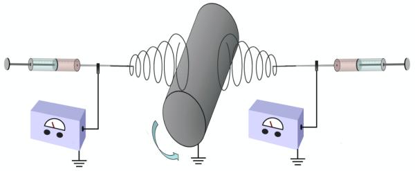
Dual extrusion electros with rotating mandrel diagram.
2.2. Scaffold morphology
Electrospun scaffolds were mounted on aluminum stubs and sputter-coated with 20 nm of gold prior to imaging with a scanning electron microscope (SEM) (FEI Quanta 400 ESEM FEG, FEI Co., Hillsboro, OR). The average microfiber diameter for each scaffold type was determined from six separate SEM images taken at 1000x magnification from three random locations on the electrospun mat. On each SEM image, the diameter of five fibers was measured using the manufacturer supplied software for a total of 30 discrete measurements per scaffold type. Nanofibers were measured from SEM images of three random locations on the electrospun mat taken at 15,000x with ten fibers measured per location for a total of 30 separate measurements. Furthermore, two disks (∅ = 6 mm) from different locations on each type of fibrous mat generated were taken and prepared for SEM imaging of a scaffold vertical cross-section. To accomplish this, each die cut scaffold was submerged in liquid nitrogen for 1 min to aid in achieving a clean vertical cross-section. After the scaffolds were thoroughly frozen, they were sectioned perpendicular to the scaffold face into thin slices using a microtome blade, mounted on aluminum stubs, sputter-coated, and imaged via SEM.
2.3. Scaffold porosity
The porosity and pore size of the electrospun meshes were determined via mercury intrusion porosimetry. First, the bulk volume and weight of each scaffold were measured. Scaffolds were then placed individually in a mercury porosimeter (Quantachrome Instruments, Boynton Beach, FL) which forced mercury through the pores of the scaffolds (n = 3) ultimately reaching a final pressure of 50 psi. For the contact angle between PCL and mercury in air, an angle of 140° was used as reported in previous work [7]. The porosity (ε) was then calculated as
in which the pore volume (Vpore) was estimated as the volume of intruded mercury per gram of scaffold and was the density of PCL. The pore size was computed from the volume versus pressure data using the manufacturer supplied software (Quantachrome Poremaster for Windows, ver. 8). For mercury porosimetry calculations regarding the PμFn scaffolds, it was assumed that the effect of fibrin on the bulk material density was negligible. Thus for these scaffolds the bulk material density was assumed to be equal to that of PCL alone.
2.4. Cell isolation and expansion
Human mesenchymal stem cells (hMSCs) were isolated from umbilical cord blood using a Ficoll-Paque gradient (Amersham-Pharmacia), plastic adherence selection, and flow cytometry verification of the MSC phenotype as previously described [25]. Specifically, the cell population isolated with flow cytometry displayed positive expression of surface markers CD29, CD44, CD73, and CD90 and negative expression of markers CD31, CD33, CD34 b, and CD45 which are oftentimes used to indicate the MSC phenotype [27-30]. Similarly sourced cells have been previously shown to successfully differentiate towards the osteoblastic and chondrocytic lineages [29-32]. After isolation, cells were expanded in general growth medium containing Iscove’s Modified Dulbecco’s Medium (Gibco), 10% MSC-qualified fetal bovine serum (FBS) (Gibco), 10% general FBS (Gibco), as well as 1% penicillin-streptomycin.
2.5. Cell seeding and culture
Electrospun scaffolds were die cut into disks 6.2 mm in diameter and ethylene oxide sterilized. Only scaffolds 0.4-0.6 mm thick were used for cell studies. Prior to seeding, scaffolds were sterilely pre-wet using a decreasing ethanol gradient (90 - 35%), rinsed with sterile water and centrifuged, then incubated in general growth medium overnight. The pre-wet scaffolds were then pressfit into 96 well plates and seeded with 75,000 passage 6 hMSCs per scaffold. Seeded scaffolds were then incubated for a three hour pre-attachment period. After the pre-attachment period, the wells were filled with chondrogenic medium containing Dulbecco’s Modified Eagle’s Medium (Gibco), 1% ITS+ premix (BD Biosciences), 50 mg/L ascorbic acid, 10−7 M dexamethasone, and 0.4 mM L-proline and incubated for the remaining 24 hour attachment period. Day 0 samples were prepared for analysis after the three hour pre-attachment period. After the 24 hour attachment period, the scaffolds were unconfined from the 96 well plates and placed in 24 well plates with chondrogenic medium for the duration of the study. Medium was changed every 3 days. Samples were taken at days 0, 7, 14, and 21, washed with PBS 3x, and prepared for analysis.
2.6. Construct imaging
For visualization via SEM, cultured constructs were fixed by incubating with 2% glutaraldehyde for one hour. Samples were then dehydrated using an increasing ethanol gradient (30 – 90%) and dried. The samples (n = 2) were then sputter-coated with 20 nm gold and imaged using SEM (JSM-6490LA, Tokyo, Japan) to visualize cell spreading and extracellular matrix production on the surface of the different scaffold types.
In preparation for confocal imaging, samples (n = 2) were fixed in 4% paraformaldehyde for 20 min then rinsed with PBS. Cell membranes were permeabilized with 0.5% Triton X-100 in PBS for 10 min then washed with 1% FBS and PBS to minimize background staining. Finally, the cells were stained for F-actin with 1:1000 Texas Red-X phalloidin (Molecular Probes) in PBS for one hour. Samples were rinsed with PBS to remove any unconjugated probes. The stained scaffolds were imaged at 594 nm and 488 nm wavelengths and 20x magnification using a confocal microscope (Leica TCS SP5 II). In addition to composite z-stack images, image slices were viewed separately in succession to examine individual cellular morphologies.
2.7. Histology
At each time point, samples (n = 2) were fixed in 10% buffered paraformaldehyde overnight at 4°C. Scaffolds were then dehydrated using an increasing ethanol gradient (30 – 90%) and stored in 100% isopropanol at 4°C. Prior to sectioning, samples were embedded in HistoPrep frozen tissue embedding medium (Fisher Scientific, Pittsburgh, PA). A cryotome (CM1850, Leica Microsystems, Bannockburn, IL) was used to cut sections 8 μm thick which were then mounted on glass slides and incubated on a slide warmer at 45°C for a minimum of 5 days.
To visualize the cartilage-like ECM produced, sections were rehydrated with water then stained with 0.1% Safranin O for 5 min. The slides were then rinsed with water and air dried. Stained sections were imaged with a light microscope (Zeiss AxioImager.Z2, Göttingen, Germany) using a peripheral camera (AxioCam MRc 5, Zeiss, Göttingen, Germany) and computer. Automatic exposure and white balance correction were applied to the captured images using the manufacturer supplied software (AxioVision 4.8, Zeiss, Göttingen, Germany).
In order to visualize cellular infiltration of the different scaffold architectures, sections were also stained with Fast Green FCF (Sigma). Sections were first washed with 1% acetic acid and then treated with 0.02% Fast Green FCF for 3 min at which point the slides were then rinsed with 1% acetic acid. The stained sections were imaged using a light microscope with automatic exposure and white balance correction applied using the manufacturer supplied software.
2.8. Biochemical assays
In an effort to determine the cellularity and glycosaminoglycan (GAG) content of the scaffolds at the various time points, samples (n = 4) were initially placed in 0.5 mL of water and frozen at −80°C. The samples were then treated with three freeze/thaw/sonicate cycles resulting in a cell lysate. The DNA content of the cell lysate was then quantified using the fluorometric PicoGreen assay kit (Molecular Probes, Eugene, OR) with an excitation wavelength of 490 nm and an emission wavelength of 520 nm. The dsDNA standards and samples were run side by side in triplicate to calculate the DNA content per scaffold.
Prior to quantifying GAG content, scaffolds were removed from the cell lysate used in determining DNA content and digested at 56°C in 0.5 mL of proteinase K (1 mg/mL proteinase K, 185 μg/mL iodacetamide, and 10 μg /mL pepstatin A in Tris/EDTA buffer containing 6.055 mg/mL tris(hydroxymethyl aminomethane and 372 μg /mL EDTA at pH 7.6). GAG content was then quantified using the 1,9-dimethymethylene blue (DMMB) assay and measured at 520 nm using a microplate reader (BIO-TEK Instrument, Winooski, VT). Chondroitin sulfate standards, cell lysate samples, and proteinase K digest samples were all run in duplicate then averaged to adjust for any experimental error. GAG concentrations determined from the cell lysate and proteinase K digest for each individual sample were summed to determine a final GAG content for each sample.
2.9. Statistical methods
Scaffold characteristics and biochemical assay results are reported as means ± standard deviation. A one-way ANOVA was performed to evaluate significant differences (p<0.05) in fiber diameter, porosity, and pore size. A two-way ANOVA was performed to evaluate significant differences (p<0.05) in construct cellularity and ECM content. If significant difference was determined, the Tukey’s HSD test was performed to make multiple comparisons between groups.
3. Results
3.1. Scaffold characterization
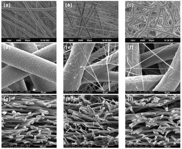
SEM images of the different scaffold types demonstrated that it was possible to fabricate electrospun mats using continuous methods to create scaffolds of two different fiber scales as well as two different materials (figure 2). Images of vertical scaffold cross-sections taken using SEM revealed that when nanofibers were incorporated into a microfiber mesh using the dual extrusion electrospinning process with a rotating mandrel, nanofibers were truly interspersed throughout the entire construct (figures 2(g)-(i)). These images also showed that, with respect to volume, the nanofiber containing scaffolds were composed of more microfibers than nanofibers due to the much lower polymer extrusion rates necessary to produce nanofibers compared to microfibers. The scaffolds that were generated consisted of fairly similarly sized microfibers with averages between 8.8 and 10.1 μm. It is important to note, however, that the PμFn scaffold fiber diameter (8.8 ± 1.1 μm) was significantly lower than the other two scaffold types (Table 1). Despite having a smaller average microfiber diameter, the PμFn scaffolds still displayed porosities similar to PμPn scaffolds as well as significantly higher porosities than microfibers alone. Examining the nanofibers in the PμPn and PμFn scaffolds, it was observed that nanofibers, regardless of composition, exhibited diameters that were primarily less than 400 nm when using these methods of fabrication. Furthermore, it was evident that the PμPn scaffolds contained a higher density of nanofibers than the PμFn scaffolds due to the different extrusion rates necessary to stably electrospin the differently composed nanofibers.
Figure 2.
Scanning electron micrograph images of the different electrospun scaffold architectures and compositions that were generated: (a, d) Pμ, (b, e) PμPn, (c, f) PμFn. Vertical cross-sections of the different scaffolds show the distribution of nanofibers with respect to microfibers throughout the thickness of the scaffold: (g) Pμ, (h) PμPn, (i) PμFn.
Table 1.
Scaffold characteristics including average micro and nanofiber diameters, porosity, and pore size. Within a particular characteristic, a scaffold type which is determined to be statistically different from both of the other scaffold types is indicated by an asterisk, “*” (p<0.05).
| Characteristic | Pμ | PμPn | PμFn |
|---|---|---|---|
| Microfiber Diameter (μm) |
10.1 ± 1.1 | 9.8 ± 1.4 | 8.8 ± 1.1* |
| Nanofiber Diameter (nm) |
0 ± 0* | 194.6 ± 45.9* | 250.0 ± 50.2* |
| Porosity (%) | 86.5 ± 0.4* | 91.8 ± 1.7 | 90.0 ± 0.7 |
| Pore Size (μm) | 32.8 ± 0.1* | 13.4 ± 2.5* | 28.1 ± 1.3* |
Porosity as determined by mercury intrusion demonstrated that the scaffolds exhibited reasonably high porosities even with the incorporation of nanofibers. In fact, the Pμ scaffolds had a significantly lower porosity than the other two scaffold groups which featured nanofibers. Despite displaying a lower porosity than the other two scaffold types, the Pμ scaffolds bore significantly larger pore sizes than the scaffolds containing nanofibers. Additionally, the PμPn scaffolds, which had the highest density of nanofibers as seen in SEM images, exhibited the smallest average pore size of all of the scaffold types.
3.2. Construct imaging
From confocal images, it was seen that after only three hours cell spreading was evident on all three scaffold types (figure 3). However, on the PμPn scaffolds cells appeared to display a flattened, broad polygonal morphology while cells on the Pμ and PμFn scaffolds exhibited more elongated and spindle-like morphologies, as indicated with arrows included on figure 3. Likewise, hMSCs on the PμPn scaffolds displayed a different pattern of cell localization as compared to the other two scaffold types. In this case, cells on Pμ and PμFn scaffolds were primarily attached and spread along microfibers while the cells on the PμPn scaffolds appeared to span the area between the microfibers more often than on the other two scaffold types.
Figure 3.
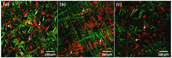
Composite z-stack confocal images showing spreading and arrangement of phalloidin labeled cells highlighting F-actin (red) on day 0 (a) Pμ (b) PμPn and (c) PμFn scaffolds (green). Arrows indicate examples of individual cell morphologies and arrangements.
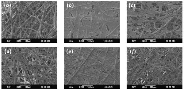
Scanning electron micrographs revealed that throughout the entire culture period cells and ECM appeared denser on the surface of scaffolds containing PCL nanofibers (figure 4). Similarly early in the culture duration, scaffolds containing nanofibers, PμPn and PμFn, displayed more cells and ECM on the scaffold surface. At a later culture duration, it was observed that fewer cells and ECM were located on the surface of the Pμ and PμFn scaffolds while the surface of the PμPn scaffolds was almost completely coated with cells and ECM.
Figure 4.
SEM images of constructs showing cells and ECM deposition on the surface of (a, d) Pμ, (b, e) PμPn, and (c, f) PμFn scaffolds on (a, b, c) day 7 and (d, e, f) day 21.
3.3. Histology
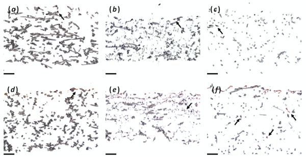
In an effort to examine the production and deposition of ECM within the different scaffolds as well as cellular infiltration, samples from each time point were cryosectioned and stained with either Safranin O for GAGs (figure 5) or Fast Green for cytoplasm (figure 6). Looking at Safranin O staining, negligible staining was seen at day 0 as expected. However as time progressed, scaffolds containing nanofibers (PμPn and PμFn) exhibited more deposition of GAGs than scaffolds composed of microfibers alone (Pμ) as was seen on the day 21 histological sections in figure 5. On the PμFn scaffolds, GAG deposits were seen deep within the interior of the scaffold in addition to the coating on the surface. These outcomes confirm the result of the DMMB biochemical assay for GAG content. With respect to cellular infiltration as viewed by Fast Green staining, it appeared that maximum cellular depth was fairly similar in all three scaffold types (Figure 6). In the uppermost portion of the scaffolds, the PμPn scaffolds displayed a more scattered distribution of cells while cells were primarily located on the surface of the other two scaffold types. However, while images showed a higher occurrence of Fast Green staining in the upper half of the PμPn scaffolds the Pμ and PμFn scaffolds appeared to exhibit greater Fast Green staining at the ultimate depth of infiltration than was observed in the PμPn group.
Figure 5.
Safranin O staining for GAGs of (a, b, c) day 0 and (d, e, f) day 21 histological sections for (a, d) Pμ, (b, e) PμPn, and (c, f) PμFnscaffolds. Arrows indicate regions of staining within the interior of the construct. Scale bars represent 100 μm.
Figure 6.

Fast Green staining for cytoplasm of day 21 histological sections for (a) Pμ day 21, (b) PμPn day 21, and (c) PμFn day 21 scaffolds. Arrows indicate regions of staining within the interior of the construct. Scale bars represent 100 μm.
3.4. Biochemical assays
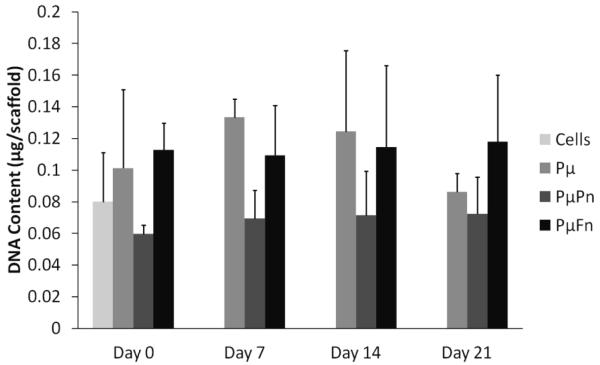
None of the scaffold types displayed a significant increase or decrease in total DNA content throughout time with respect to the initial cell seeding suspension (figure 7). This demonstrated that cell numbers remained fairly constant throughout the duration of the study regardless of scaffold composition and architecture.
Figure 7.
Scaffold cellularity as determined by total DNA content per scaffold. In this instance, the group indicated as “Cells” denotes the DNA content of the initial cell suspension used to seed each of the scaffold types on day 0. DNA contents are represented as mean ± standard deviation for n = 4 samples.
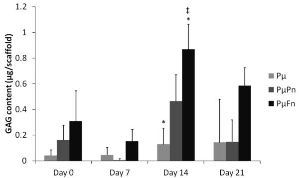
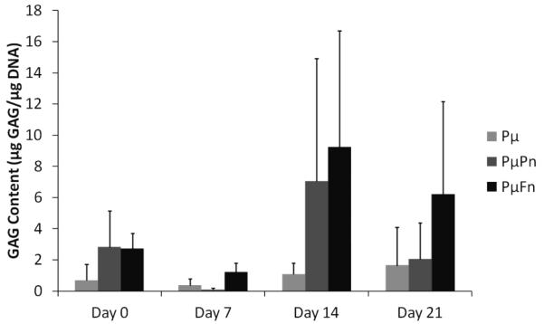
To assess the effect of scaffold architecture on the production of GAGs, a common cartilaginous ECM component, by hMSCs, the DMMB biochemical assay for sulfated GAGs was performed. At day 14, the PμFn samples displayed significantly higher GAG contents (0.87 ± 0.2 μg per scaffold) than both of the other scaffold types at the various time points with exception to the PμPn samples on day 14 (0.46 ± 0.2 μg per scaffold). (figure 8). No significant difference was observed in GAG deposition with respect to time for any of the three scaffold types. When GAG content was normalized to DNA content, trends appeared similar to those of the GAG data that was not normalized (figure 9). However, there was no statistically significant difference in normalized GAG contents among the different scaffold types. Similarly, there was no statistical difference in GAG/DNA amounts with time for any scaffold type.
Figure 8.
GAG content of scaffolds at days 0, 7, 14, and 21 as determined by the DMMB assay. GAG contents are represented as mean ± standard deviation for n = 4 samples. Different scaffold types marked with an asterisk, “*”, indicate significant difference in GAG content for a specific time point. Statistical significance of a particular scaffold type at a specific culture period compared to both of the other scaffold types at every other time point is indicated by a “‡”.
Figure 9.
GAG content normalized by total DNA content per scaffold at days 0, 7, 14, and 21 as determined by the DMMB assay. Normalized GAG contents are represented as mean ± standard deviation for n = 4 samples. ss
4. Discussion
In order for tissue engineering to progress, it is becoming increasingly important to develop materials that function beyond mere support structures for cells. Previous work has shown that electrospun PCL scaffolds support the attachment and deposition of cartilage-like ECM by chondrocytes and MSCs possibly because the three dimensional architecture of electrospun PCL resembles the morphology of collagenous ECM [5, 33]. As such, it follows that scaffolds more closely resembling the scale and architecture of native ECM would lead to improved cellular responses. Previous studies have shown that scaffolds containing both micro and nanofibers result in better cellular adhesion, viability, and scaffold infiltration as well as ECM production when compared to single scaled fiber controls [10, 11, 13, 14, 34]. The benefit of multiscale fibrous scaffold generation by continuous means as investigated here over previously described methods, such as tandem melt deposition with electrospinning or layer by layer electrospinning, is that fabrication via the dual extrusion method with a rotating mandrel affords more reproducibility due to fewer steps and minimized human influence on fabrication. Also, scaffolds formed in this manner demonstrate a homogenous distribution of micro and nanofibers throughout the entire scaffold while other fabrication techniques often lead to stratified compositions. While Soliman et al. showed that simultaneous dual extrusion was useful for the production of multiscale fibrous scaffolds, methods described in the current work demonstrate the added value of fabricating scaffolds with fibers composed of different materials in an uninterrupted fashion [14]. This additional feature increases the capacity of this system to fine tune the generation of a particular scaffold for a specific application.
To examine the cellular response to nanofibers while trying to maintain larger pore sizes for cellular infiltration, different scaffolds were fabricated containing both micro and nanofibers. This was accomplished by extruding polymer solutions at different rates and applied voltages from opposite sides of a rotating mandrel. In this manner, scaffolds containing both microfibers and nanofibers as well as fibers of two different materials, PCL and fibrin, were generated. A higher voltage was needed to produce fibrin nanofibers in a reproducible manner than was needed for the production of PCL nanofibers, quite possibly due to a difference in viscosity, surface tension, and/or conductivity of the polymer solutions used. As a result of this difference, the diameter of the microfibers within the PμFn scaffolds was significantly lower than that of the microfibers in the other two scaffold types. It is likely that the change in the electric field of the whole system was responsible for the observed slight decrease in PCL microfiber diameter for the PμFn scaffolds compared to the PμPn scaffolds. Images of vertical scaffold cross-sections demonstrated that this fabrication method was successful in generating scaffolds in which the different fiber types were well mixed throughout the entire scaffold (figures 2(g)-(i)). The nanofiber containing scaffolds that were generated contained visibly different nanofiber densities with the PμPn scaffolds exhibiting more densely packed nanofibers. As a result, despite having comparable porosities the PμPn scaffolds displayed smaller pore sizes than the PμFn scaffolds.
Confocal images taken shortly after cell attachment showed that hMSCs on scaffolds containing PCL nanofibers, PμPn, were broad and flattened and appeared to span inter-microfiber gaps (Figure 3). Likewise, SEM and histology images revealed that scaffolds containing PCL nanofibers exhibited a surface densely coated with cells and ECM. This is possibly due to the smaller pore sizes of the PμPn scaffolds as a result of dense nanofiber packing which could partially restrict cellular infiltration. Fast Green staining of histological sections supports this theory showing that while the maximum cellular infiltration was similar for all three scaffold types, proportionally more of the cells in the PμPn scaffolds remained in the upper region of the scaffold. Compared to the PμPn scaffolds, the Pμ and PμFn scaffolds appeared to exhibit greater Fast Green staining at the ultimate depth of infiltration. The difference in cellular infiltration patterns of the PμPn scaffolds in comparison to the Pμ and PμFn scaffolds may be due to the relative pore sizes of the different scaffold types. Similarly, it is possible that the distribution of nanofibers with respect to microfibers within the PμPn scaffolds provided a method to assist cells in spanning inter-microfiber gaps. These cellular bridges in turn may have resulted in the dispersion of cells in the upper portion of the scaffold while within this region Pμ and PμFn scaffolds displayed cells primarily on the scaffold surface.
Confocal images taken three hours after initial cell attachment revealed that hMSCs on Pμ and PμFn scaffolds spread maintaining an elongated, spindle-like morphology characteristic of MSCs. On these two scaffolds, hMSCs primarily attached along the length of microfibers as seen in confocal and SEM images (figures 3 and 4). In contrast, cells attached to PμPn scaffolds spread appearing broad and flat spanning the space between microfibers. As such, the cells spread on the nanofibers of the PμPn scaffolds resembling two-dimensional cultures as opposed to the intended three-dimensional scaffold environment. Furthermore, the broad and flat hMSC morphology could potentially have an adverse effect on tissue development within a scaffold as previous studies have shown that a flat polygonal cell shape sometimes precedes reduced proliferation and chondrogenic differentiation capacity compared to more elongated cells with spindle-like morphologies [35-37].
In a serum-free culture environment without additional growth factors, it is not uncommon to see limited cellular proliferation [6, 38]. Here there was neither a significant increase nor decrease in total DNA content of all scaffold types over the course of 21 days. This indicated that all three scaffold types were sufficient for supporting MSC culture. Sometimes it is desirable to induce increased cellular proliferation as greater cell numbers may lead to increased ECM deposition. However, as cells proliferate metabolic resources are somewhat allocated away from matrix production. In this fashion, when attempting to generate ample ECM within a polymeric scaffold it is important to not only consider the effect of the scaffold on cellular proliferation but also on the ECM content of the scaffolds as culture progresses. As such in addition to quantifying the DNA content of the different scaffold types over time, the GAG content of the scaffolds was also measured. From the DMMB biochemical assay, it was determined that PCL microfibers interspersed with fibrin nanofibers exhibited significantly higher GAG contents at day 14 than the PCL microfiber control group. Furthermore, at day 14 the PμFn samples contained more GAG total than both of the other scaffold types at the various time points with exception to the PμPn samples on day 14. These results suggest that the presence of nanofibers, specifically fibrin nanofibers, within the scaffold had a positive influence on the production of GAGs by hMSCs in fourteen days of culture even in the absence of growth factors. It was hypothesized that the inclusion of nanofibers would lead to a significant increase in GAG production by the differentiating cells because nanoscale features more closely resemble the components of native ECM and as such may lead to improved cellular responses [5, 6]. However, both the total GAG content of the scaffolds and GAG/DNA amounts stayed relatively constant throughout the entire culture duration. One possible explanation for this is that some soluble GAGs produced by the cells may have diffused into the surrounding culture medium rather than remaining within the scaffold. Evidence of this behavior has been shown in previous studies measuring GAG content as a diagnostic of tissue engineered cartilage development as well as cartilage explant culture [33, 39-41].
Histological sections exhibited increased proteoglycan deposits with the incorporation of nanofibers within microfiber meshes as indicated by Safranin O staining. This suggests that the cells responded to the nanofibers in the scaffolds by producing more ECM as compared to scaffolds composed of microfibers alone. This evidence supports the hypothesis that a scaffold architecture more closely resembling native ECM, whether it is with respect to scale or composition, could be advantageous for cartilage-like matrix production and deposition.
While it is difficult to make direct comparisons between scaffolds that have been fabricated using different extrusion rates and post-fabrication processing techniques, this work does show that it is feasible to produce biodegradable nonwoven fibrous meshes composed of microfibers mixed with nanofibers throughout an entire scaffold. Also, it is possible to produce such multiscale scaffolds containing fibers of two discrete compositions. One of the limitations of the electrospinning technique is that processing parameters such as extrusion flow rate and voltage are dependent on the polymer solution composition. Due to the processing limitations necessary to produce nanofibers from distinct compositions it is necessary to further examine the effect extrusion rates have on scaffold characteristics and cellular responses. Cell culture on these multiscale scaffolds has shown that the inclusion of nanofibers does not negatively affect cell growth or matrix production. In fact, histological images suggest that the inclusionof nanofibers is beneficial towards the production and distribution of GAGs. The interaction between fiber composition, scale, porosity, and pore size as related to the development of ECM should be more closely studied. Future work should look to fine tune the density of nanofibers with respect to microfibers in an effort to harness the positive influence of nanofibers on cellular responses, such as improved ECM production and cell attachment, while minimizing any negative effects such as limited infiltration.
Acknowledgements
The authors appreciate the Indo-US Science and Technology Forum under the Joint Centre on “Cell Targeted Diagnostics and Therapy Using Nanomaterials” for supporting a collaborative research exchange facilitating cooperative research efforts between international institutions. The authors are also thankful to support of the Nanomission, Department of Science and Technology, the Government of India, under a grant for theragnostics and regenerative engineering using nanostructured materials. Efforts towards developing multiscale fibrous scaffolds for tissue engineering applications have been supported from funding by the National Institutes of Health (R01 AR57083). Furthermore, E.J. Levorson is grateful for assistance from the Rice Institute of Biosciences and Bioengineering’s Biotechnology Training Grant (NIH T32 GM08362).
6. References
- 1.Lowery JL, Datta N, Rutledge GC. Effect of fiber diameter, pore size and seeding method on growth of human dermal fibroblasts in electrospun poly(ε-caprolactone) fibrous mats. Biomaterials. 2010;31(3):491–504. doi: 10.1016/j.biomaterials.2009.09.072. [DOI] [PubMed] [Google Scholar]
- 2.Alvarez-Barreto J, Linehan S, Shambaugh R, Sikavitsas V. Flow perfusion improves seeding of tissue engineering scaffolds with different architectures. Annals of Biomedical Engineering. 2007;35(3):429. doi: 10.1007/s10439-006-9244-z. [DOI] [PubMed] [Google Scholar]
- 3.Gomes ME, Holtorf HL, Reis RL, Mikos AG. Influence of the porosity of starch-based fiber mesh scaffolds on the proliferation and osteogenic differentiation of bone marrow stromal cells cultured in a flow perfusion bioreactor. Tissue Engineering. 2006;12(4):801–809. doi: 10.1089/ten.2006.12.801. [DOI] [PubMed] [Google Scholar]
- 4.Li W-J, Laurencin CT, Caterson EJ, Tuan RS, Ko FK. Electrospun nanofibrous structure: A novel scaffold for tissue engineering. Journal of Biomedical Materials Research. 2002;60(4):613–621. doi: 10.1002/jbm.10167. [DOI] [PubMed] [Google Scholar]
- 5.Li W-J, Tuli R, Huang X, Laquerriere P, Tuan RS. Multilineage differentiation of human mesenchymal stem cells in a three-dimensional nanofibrous scaffold. Biomaterials. 2005;26(25):5158. doi: 10.1016/j.biomaterials.2005.01.002. [DOI] [PubMed] [Google Scholar]
- 6.Li W-J, Danielson KG, Alexander PG, Tuan RS. Biological response of chondrocytes cultured in three-dimensional nanofibrous poly(ε-caprolactone) scaffolds. Journal of Biomedical Materials Research Part A. 2003;67A(4):1105–1114. doi: 10.1002/jbm.a.10101. [DOI] [PubMed] [Google Scholar]
- 7.Pham QP, Sharma U, Mikos AG. Electrospun poly(ε-caprolactone) microfiber and multilayer nanofiber/microfiber scaffolds: Characterization of scaffolds and measurement of cellular infiltration. Biomacromolecules. 2006;7(10):2796–2805. doi: 10.1021/bm060680j. [DOI] [PubMed] [Google Scholar]
- 8.Shalumon KT, Binulal NS, Deepthy M, Jayakumar R, Manzoor K, Nair SV. Preparation, characterization and cell attachment studies of electrospun multi-scale poly(caprolactone) fibrous scaffolds for tissue engineering. Journal of Macromolecular Science, Part A. 2011;48(1):21–30. [Google Scholar]
- 9.Srinivasan S, Jayakumar R, Chennazhi KP, Levorson EJ, Mikos AG, Nair SV. Multiscale fibrous scaffolds in regenerative medicine. Advances in Polymer Science. 2012;246:1–20. [Google Scholar]
- 10.Park SH, Kim TG, Kim HC, Yang D-Y, Park TG. Development of dual scale scaffolds via direct polymer melt deposition and electrospinning for applications in tissue regeneration. Acta Biomaterialia. 2008;4(5):1198–1207. doi: 10.1016/j.actbio.2008.03.019. [DOI] [PubMed] [Google Scholar]
- 11.Tuzlakoglu K, Bolgen N, Salgado A, Gomes M, Piskin E, Reis R. Nano- and micro-fiber combined scaffolds: A new architecture for bone tissue engineering. Journal of Materials Science: Materials in Medicine. 2005;16(12):1099–1104. doi: 10.1007/s10856-005-4713-8. [DOI] [PubMed] [Google Scholar]
- 12.Martins A, Pinho ED, Correlo VM, Faria S, Marques AP, Reis RL, Neves NM. Biodegradable nanofibers-reinforced microfibrous composite scaffolds for bone tissue engineering. Tissue Engineering Part A. 2010;16(12):3599–3609. doi: 10.1089/ten.TEA.2009.0779. [DOI] [PubMed] [Google Scholar]
- 13.Mota C, Puppi D, Dinucci D, Errico C, Bártolo P, Chiellini F. Dual-scale polymeric constructs as scaffolds for tissue engineering. Materials. 2011;4(3):527–542. doi: 10.3390/ma4030527. [DOI] [PMC free article] [PubMed] [Google Scholar]
- 14.Soliman S, Pagliari S, Rinaldi A, Forte G, Fiaccavento R, Pagliari F, Franzese O, Minieri M, Di Nardo P, Licoccia S, Traversa E. Multiscale three-dimensional scaffolds for soft tissue engineering via multimodal electrospinning. Acta Biomaterialia. 2010;6(4):1227–1237. doi: 10.1016/j.actbio.2009.10.051. [DOI] [PubMed] [Google Scholar]
- 15.Chen W-C, Yao C-L, Wei Y-H, Chu IM. Evaluating osteochondral defect repair potential of autologous rabbit bone marrow cells on type ii collagen scaffold. Cytotechnology. 2011;63(1):13–23. doi: 10.1007/s10616-010-9314-9. [DOI] [PMC free article] [PubMed] [Google Scholar]
- 16.Kawasaki K, Ochi M, Uchio Y, Adachi N, Matsusaki M. Hyaluronic acid enhances proliferation and chondroitin sulfate synthesis in cultured chondrocytes embedded in collagen gels. Journal of Cellular Physiology. 1999;179(2):142–148. doi: 10.1002/(SICI)1097-4652(199905)179:2<142::AID-JCP4>3.0.CO;2-Q. [DOI] [PubMed] [Google Scholar]
- 17.Im G-I. Chondrogenesis from mesenchymal stem cells derived from adipose tissue on the fibrin scaffold. Current Applied Physics. 2005;5(5):438–443. [Google Scholar]
- 18.Matthews JA, Boland ED, Wnek GE, Simpson DG, Bowlin GL. Electrospinning of collagen type ii: A feasibility study. Journal of Bioactive and Compatible Polymers. 2003;18(2):125–134. [Google Scholar]
- 19.Duggal S, Frønsdal KB, Szöke K, Shahdadfar A, Melvik JE, Brinchmann JE. Phenotype and gene expression of human mesenchymal stem cells in alginate scaffolds. Tissue Engineering Part A. 2009;15(7):1763–1773. doi: 10.1089/ten.tea.2008.0306. [DOI] [PubMed] [Google Scholar]
- 20.Vinatier C, Mrugala D, Jorgensen C, Guicheux J, Noël D. Cartilage engineering: A crucial combination of cells, biomaterials and biofactors. Trends in Biotechnology. 2009;27(5):307–314. doi: 10.1016/j.tibtech.2009.02.005. [DOI] [PubMed] [Google Scholar]
- 21.Kavalkovich KW, Boynton RE, Murphy JM, Barry F. Chondrogenic differentiation of human mesenchymal stem cells within an alginate layer culture system. In Vitro Cellular & Developmental Biology - Animal. 2002;38(8):457–466. doi: 10.1290/1071-2690(2002)038<0457:cdohms>2.0.co;2. [DOI] [PubMed] [Google Scholar]
- 22.Ma HL, Hung SC, Lin SY, Chen YL, Lo WH. Chondrogenesis of human mesenchymal stem cells encapsulated in alginate beads. Journal of Biomedical Materials Research Part A. 2003;64A(2):273–281. doi: 10.1002/jbm.a.10370. [DOI] [PubMed] [Google Scholar]
- 23.Medrado GCB, Machado CB, Valerio P, Sanches MD, Goes AM. The effect of a chitosan-gelatin matrix and dexamethasone on the behavior of rabbit mesenchymal stem cells. Biomedical Materials. 2006;1(3):155. doi: 10.1088/1748-6041/1/3/010. [DOI] [PubMed] [Google Scholar]
- 24.Geng X, Kwon O-H, Jang J. Electrospinning of chitosan dissolved in concentrated acetic acid solution. Biomaterials. 2005;26(27):5427–5432. doi: 10.1016/j.biomaterials.2005.01.066. [DOI] [PubMed] [Google Scholar]
- 25.Perumcherry SR, Chennazhi KP, Nair SV, Menon D, Afeesh R. A novel method for the fabrication of fibrin-based electrospun nanofibrous scaffold for tissue-engineering applications. Tissue Engineering Part C: Methods. 2011;17(11):1121–1130. doi: 10.1089/ten.TEC.2010.0734. [DOI] [PubMed] [Google Scholar]
- 26.Blomback B, Blomback M, Edman P, Hessel B. Human fibrinopeptides. Isolation, characterization and structure. Biochimica et Biophysica Acta. 1966;115(2):371–396. doi: 10.1016/0304-4165(66)90437-5. [DOI] [PubMed] [Google Scholar]
- 27.Cavallo C, Cuomo C, Fantini S, Ricci F, Tazzari PL, Lucarelli E, Donati D, Facchini A, Lisignoli G, Fornasari PM, Grigolo B, Moroni L. Comparison of alternative mesenchymal stem cell sources for cell banking and musculoskeletal advanced therapies. Journal of Cellular Biochemistry. 2011;112(5):1418–1430. doi: 10.1002/jcb.23058. [DOI] [PubMed] [Google Scholar]
- 28.Capelli C, Gotti E, Morigi M, Rota C, Weng L, Dazzi F, Spinelli O, Cazzaniga G, Trezzi R, Gianatti A, Rambaldi A, Golay J, Introna M. Minimally manipulated whole human umbilical cord is a rich source of clinical-grade human mesenchymal stromal cells expanded in human platelet lysate. Cytotherapy. 2011;13(7):786–801. doi: 10.3109/14653249.2011.563294. [DOI] [PubMed] [Google Scholar]
- 29.Kern S, Eichler H, Stoeve J, Klüter H, Bieback K. Comparative analysis of mesenchymal stem cells from bone marrow, umbilical cord blood, or adipose tissue. Stem Cells. 2006;24(5):1294–1301. doi: 10.1634/stemcells.2005-0342. [DOI] [PubMed] [Google Scholar]
- 30.Lee OK, Kuo TK, Chen W-M, Lee K-D, Hsieh S-L, Chen T-H. Isolation of multipotent mesenchymal stem cells from umbilical cord blood. Blood. 2004;103(5):1669–1675. doi: 10.1182/blood-2003-05-1670. [DOI] [PubMed] [Google Scholar]
- 31.Ramis JM, Rubert M, Vondrasek J, Gayà A, Lyngstadaas SP, Monjo M. Effect of enamel matrix derivative and of proline-rich synthetic peptides on the differentiation of human mesenchymal stem cells toward the osteogenic lineage. Tissue Engineering Part A. doi: 10.1089/ten.tea.2011.0404. Epub ahead of print, 19 March 2012. [DOI] [PubMed] [Google Scholar]
- 32.Nitya G, Nair GT, Mony U, Chennazhi KP, Nair SV. In vitro evaluation of electrospun pcl/nanoclay composite scaffold for bone tissue engineering. Journal of Materials Science: Materials in Medicine. doi: 10.1007/s10856-012-4647-x. Epub ahead of print, 3 May 2012. [DOI] [PubMed] [Google Scholar]
- 33.Liao J, Guo X, Grande-Allen KJ, Kasper FK, Mikos AG. Bioactive polymer/extracellular matrix scaffolds fabricated with a flow perfusion bioreactor for cartilage tissue engineering. Biomaterials. 2010;31(34):8911–8920. doi: 10.1016/j.biomaterials.2010.07.110. [DOI] [PMC free article] [PubMed] [Google Scholar]
- 34.Kim SJ, Jang DH, Park WH, Min B-M. Fabrication and characterization of 3-dimensional plga nanofiber/microfiber composite scaffolds. Polymer. 2010;51(6):1320–1327. [Google Scholar]
- 35.Seeberger KL, Dufour JM, Shapiro AMJ, Lakey JRT, Rajotte RV, Korbutt GS. Expansion of mesenchymal stem cells from human pancreatic ductal epithelium. Laboratory Investigation. 2006;86(2):141–153. doi: 10.1038/labinvest.3700377. [DOI] [PubMed] [Google Scholar]
- 36.Mets T, Verdonk G. In vitro aging of human bone marrow derived stromal cells. Mechanisms of Ageing and Development. 1981;16(1):81–89. doi: 10.1016/0047-6374(81)90035-x. [DOI] [PubMed] [Google Scholar]
- 37.Neuhuber B, Swanger SA, Howard L, Mackay A, Fischer I. Effects of plating density and culture time on bone marrow stromal cell characteristics. Experimental Hematology. 2008;36(9):1176–1185. doi: 10.1016/j.exphem.2008.03.019. [DOI] [PMC free article] [PubMed] [Google Scholar]
- 38.Tonti GA, Mannello F. From bone marrow to therapeutic applications: Different behaviour and genetic/epigenetic stability during mesenchymal stem cell expansion in autologous and foetal bovine sera? International Journal of Development Biology. 2008;52:1023–1032. doi: 10.1387/ijdb.082725gt. [DOI] [PubMed] [Google Scholar]
- 39.Mahmood TA, Shastri VP, Van Blitterswijk CA, Langer R, Riesle J. Tissue engineering of bovine articular cartilage within porous poly(ether ester) copolymer scaffolds with different structures. Tissue Engineering. 2005;11(7-8):1244–53. doi: 10.1089/ten.2005.11.1244. [DOI] [PubMed] [Google Scholar]
- 40.Wang L, Seshareddy K, Weiss ML, Detamore MS. Effect of initial seeding density on human umbilical cord mesenchymal stromal cells for fibrocartilage tissue engineering. Tissue Engineering Part A. 2009;15(5):1009–1017. doi: 10.1089/ten.tea.2008.0012. [DOI] [PMC free article] [PubMed] [Google Scholar]
- 41.Bolis S, Handley CJ, Comper WD. Passive loss of proteoglycan from articular cartilage explants. Biochimica et Biophysica Acta. 1989;993(2-3):157–67. doi: 10.1016/0304-4165(89)90158-x. [DOI] [PubMed] [Google Scholar]


