Abstract
Purpose In video surgery, and more specifically in arthroscopy, one of the major problems is positioning the camera and instruments within the anatomic environment. The concept of computer-guided video surgery has already been used in ear, nose, and throat (ENT), gynecology, and even in hip arthroscopy. These systems, however, rely on optical or mechanical sensors, which turn out to be restricting and cumbersome. The aim of our study was to develop and evaluate the accuracy of a navigation system based on electromagnetic sensors in video surgery.
Methods We used an electromagnetic localization device (Aurora, Northern Digital Inc., Ontario, Canada) to track the movements in space of both the camera and the instruments. We have developed a dedicated application in the Python language, using the VTK library for the graphic display and the OpenCV library for camera calibration.
Results A prototype has been designed and evaluated for wrist arthroscopy. It allows display of the theoretical position of instruments onto the arthroscopic view with useful accuracy.
Discussion The augmented reality view represents valuable assistance when surgeons want to position the arthroscope or locate their instruments. It makes the maneuver more intuitive, increases comfort, saves time, and enhances concentration.
Keywords: arthroscopy, augmented reality, computer-guided surgery, wrist
One of the main problems in endoscopic surgery is positioning and placing both the optical device and the surgical instruments within the operative field. Triangulation of the instruments is only mastered after years of training. To smooth the learning curve, computer-assisted solutions have been developed in some disciplines such as in abdominal laparoscopy,1 arthroscopy of the temporomandibular joint,2 and hip arthroscopy.3
These computer-assisted endoscopic surgery systems require merging anatomical data and instrument positional data to enable the surgeons to orient themselves in a limited surgical field.4 The anatomical data consist of a three-dimensional (3D) computed tomography (CT) or magnetic resonance imaging (MRI) reconstruction of the surgical field, whereas electromagnetic sensors provide data regarding the position of the instruments.
In wrist arthroscopy, there is a long learning curve in mastering the position and placement of the arthroscope and instruments.5 6 To our knowledge, no computer-assisted wrist arthroscopy system has been previously reported.
The aim of this study was to develop and evaluate the feasibility of a computer-assisted system for arthroscopic surgery of the wrist.
Material and Methods
A left forearm cadaver specimen was vertically mounted with 80 N of traction (Fig. 1a).
Fig. 1a–d.
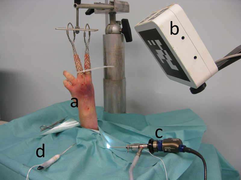
Setup of the navigation system for wrist arthroscopy. (a) Wrist in traction. (b) Electromagnetic field transmitter. (c) Arthroscope with an electromagnetic sensor. (d) Probe with two electromagnetic sensors.
The augmented reality navigation system was composed of an arthroscopic image collection device, an electromagnetic localization system, and a data processing device.
The arthroscopic image collection device consisted of a 2.4-mm 30° angle arthroscope (H3-Z HD camera head, Stortz, Tuttlingen, Germany) and a high-resolution camera and video tower (Image 1 Hub, Storz, Tuttlingen, Germany) (Fig. 1b, c). The electromagnetic localization system (Aurora, Northern Digital Inc., Ontario, Canada) was used to track the movements of the arthroscope and a small ferromagnetic arthroscopic probe designed to reduce electromagnetic interference. This device had an electromagnetic field transmitter (planar field generator) and solenoid-shaped electromagnetic sensors with six degrees of freedom (DOF) connected to a sensor interface unit. The electromagnetic field transmitter and sensor interface units were linked to a system control unit. Two electromagnetic sensors were attached to the probe, and an electromagnetic sensor was attached to the arthroscope (Fig. 1d). A system control unit gave the sensor position and orientation in real-time, with an accuracy of 1 mm/degree.7 These data were transmitted to the data processing device via a serial port.
The data processing device consisted of a laptop computer and an application designed to generate augmented reality images. This application was written using the Python programing language for software integration8 and used the open source library Visualization Toolkit (VTK)9 for the graphic display, and the open source library OpenCV10 for the processing of video images. The application captured the spatial position of the electromagnetic sensors in real time from the data flow originating from the electromagnetic localization system.
The probe, arthroscope, camera, and wrist underwent calibration.
Calibration of the probe was accomplished using the pivot method,11 which tracked successive positions of the electromagnetic sensors at the tip of the probe during a circumduction movement and provided the relative position of the probe tip with respect to the position of electromagnetic sensors (Fig. 2).
Fig. 2.
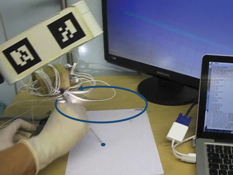
Probe calibration following the pivot method. With a circumduction movement of the probe around the tip, the navigation system determined the relative position of the probe tip with respect to the position of the electromagnetic sensor.
Arthroscope calibration was done through palpation of three reference points, which provided the relative position of the arthroscope tip with respect to the position of the electromagnetic sensor.
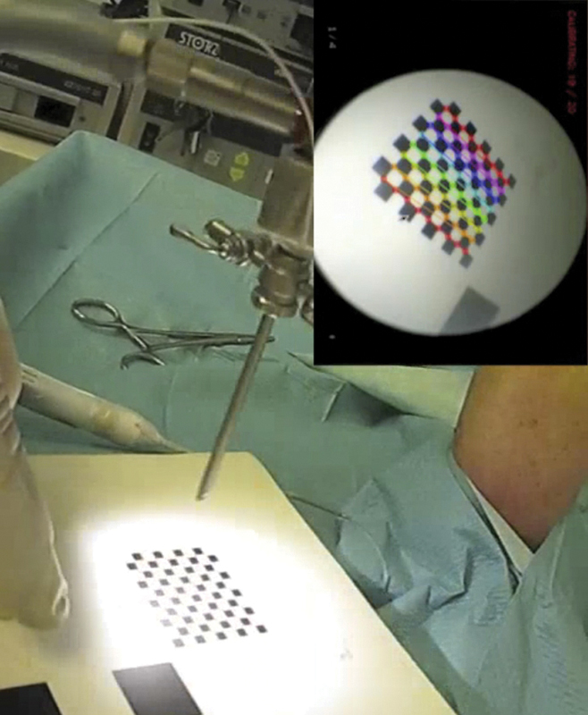
The endoscopic camera was calibrated following the method described by Tsai12 (Fig. 3). Calibration ended with the localization of three reference points on the dorsal aspect of the cadaver wrist, including the second and fifth metacarpal heads and the Lister tubercle.
Fig. 3.
Endoscopic camera calibration according to the method described by Tsai. A checkered pattern with known dimensions was localized in space through palpation with the probe, then recorded for a few seconds with the arthroscope, while the electromagnetic localization device collected the positions of the arthroscope-associated sensor. The navigation system then determined intrinsic and extrinsic parameters of the optic-camera set.
Results (Video 1)
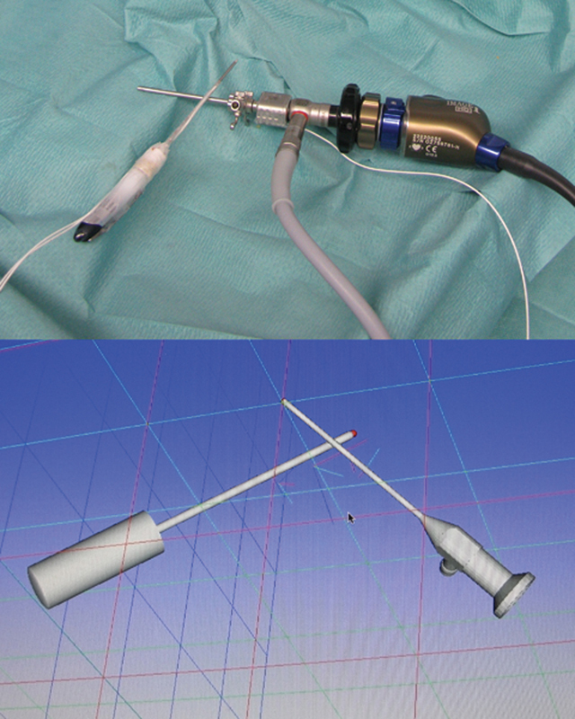
Video 1From the initial calibration data and the real-time data collected by the electromagnetic localization device, the data processing device produced a virtual reality model of the probe, the arthroscope, and the wrist (Figs. 4, 5a, b).
Fig. 4.
After probe and arthroscope calibration, the navigation system displayed a virtual reality model of the probe and the arthroscope.
Fig. 5a–c.
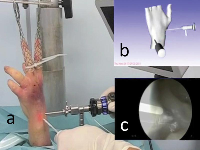
Navigation system for wrist arthroscopy: (a) Real view of the surgical field. (b) Virtual reality: scene representing the surgical field, where the arthroscope, probe, and wrist have been modeled. (c) Augmented reality: superimposition of the arthroscope shape onto the arthroscopic image, modeled in virtual reality.
An overview of Figs. 1-5. Online content including video sequences viewable at: www.thieme-connect.com/ejournals/html/doi/10.1055/s-0033-1359321.
The data processing device simulated arthroscopic images by positioning and orientating the point of view within the virtual reality according to the arthroscope position and the intrinsic and extrinsic parameters of the optic-camera set.
Through the superimposition of these virtual arthroscopic images onto real arthroscopic images, the data processing device generated augmented reality images (Fig. 5c).
Discussion
The purpose of computerized navigation systems in surgery is to display information through which surgeons can better orient themselves within the space of the operating field and within the anatomical space of the patient. This information comes from data that can be acquired before or during the intervention according to various sources: 3D reconstruction of tomographic data, fluoroscopic images, palpation of anatomical landmarks, or kinematic data. This information is presented graphically in one of two modes: augmented virtuality and augmented reality.
“Virtuality continuum” is a phrase used to describe a concept that there is a continuous scale ranging between the completely virtual (i.e., virtuality), and the completely real (i.e., reality). The reality–virtuality continuum therefore encompasses all possible variations and compositions of real and virtual objects. It includes both augmented reality, where the virtual augments the real, and augmented virtuality, where real data augment the virtual environment. These typically involve computer-assisted navigation systems for hip or knee athroplasty, where the positioning of the prosthesis is projected on an anatomical model.
Augmented reality consists of modeling virtual data on a real image. Since Thomas Caudell invented this concept in the early 1990s,13 augmented reality has been applied to many domains.14 In medicine, it is found in applications that use an optical device and/or a camera such as celioscopy,4 arthroscopy,15 endoscopy,16 17 and microsurgery.18 In each application, the purpose of augmented reality was to simplify and accelerate the access to complex data by associating them with the surgical field of view.
Most surgical navigation systems rely on optical or mechanical sensors, which are restricting and cumbersome for wrist arthroscopy, which is cluttered with many visual obstacles such as the patient's limb, the traction column, the surgeon's hands, and instruments.
Although optoelectronic localization devices are frequently used in computer-assisted surgery.3 the sensors cannot be localized once they have left the field of vision of the stereo camera.4 Mechatronic localization systems, which incorporate mechanical and electronic engineering, are less frequently used. A mechatronic localization device has been developed and evaluated for hip arthroscopy,3 19 but, despite miniaturization, the devices remain bulky and rigid.19
Electromagnetic localization devices do not have these drawbacks, since electromagnetic sensors can be localized even when they are concealed and are quite small, which makes them more suitable for navigation in endoscopic surgery. A variety of electromagnetic navigation systems are already being used routinely for ear, nose, and throat (ENT) procedures,20 thanks to various commercial navigation stations (InstaTrak 3500 Plus, General Electric Healthcare Surgery, Lawrence, Massachusetts, USA; StealthStation S7 System, Medtronic Navigation, Louisville, Kentucky, USA). The accuracy of these navigation systems can be compared with the accuracy of navigation systems based on optoelectronic localization devices.21
Electromagnetic localization devices have a few drawbacks, however, such as the need for. connecting cables between the electromagnetic sensors and the arthroscope, motorized instruments, the probe, and the control unit. The electromagnetic field transmitter is usually a box with a volume of ∼1 liter (L), it is nonsterilizable and emits a 50-cm cubic electromagnetic field, which can encompass the operating field in wrist arthroscopy, provided that it is limited to the dorsal side of the wrist. We therefore have to consider the introduction of an electromagnetic field transmitter in a sterile box that is fixed to or incorporated into the traction tower.
The main shortcoming of electromagnetic localization devices remains the lack of accuracy linked to distortion of the electromagnetic field due to the presence of ferromagnetic objects such as the traction tower, arthroscope, and instruments.22 23 24 Yaniv et al7 found a mean squared error (MSE) of 1.01 mm and 1.54°, respectively, for the sensor position and orientation. Nonferromagnetic instruments made of plastic, ceramic, aluminum, or titanium have been developed to overcome this problem.
Fischer determined that two sensors, one placed in parallel to the arthroscope axis and the other one placed perpendicularly, minimized these inaccuracies.25 For the arthroscope, he envisioned arthroscope-integrated sensors (Fig. 6a) or sensors integrated into a sleeve, which would be independent at the distal tip of the arthroscope (Fig. 6b).
Fig. 6a,b.
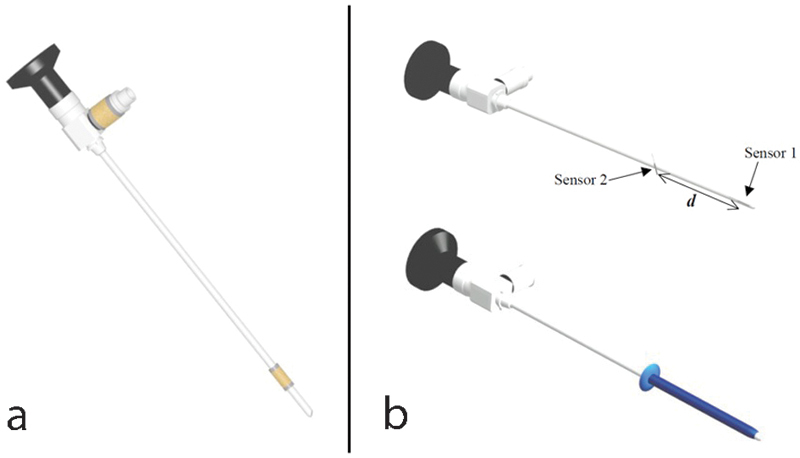
Diagram representing the optimum layout of arthroscope sensors according to Fischer, reproduced with the author's agreement. (a) Arthroscope with two integrated sensors. The most distal sensor has to be the closest to the arthroscope tip to minimize the localization inaccuracy. (b) Sleeve with two integrated sensors that can be placed at the distal part of the arthroscope or instruments. The distance between sensors has to be reduced to minimize the measurement errors of the arthroscope rotation axis.
To simplify the registration problem of using an oblique optical field because of the 30° angled scope, we chose to block the camera rotation around the axis of the optic device and to apply the method described by Tsai.12 However, Wu and Jaramaz26 have described a registration method that takes into account the camera rotation around the optical axis, which will be the next development in designing a navigation system dedicated to wrist arthroscopy. Further research is needed to identify the pedagogical and clinical applications.
Acknowledgment
We would like to thank:
• Stéphane Nicolau, PhD, IRCAD, 1 Place de l'Hôpital, 67091 Strasbourg, France
• Miryam Obdeijn, MD, Department of Plastic, Reconstruction and Hand Surgery, Academic Medical Center, University of Amsterdam, The Netherlands
• EWAS (European Wrist Arthroscopy Society) for providing us a fresh cadaver wrist
• Karl Storz (Tuttlingen, Germany) has provided the arthroscopy column
Footnotes
Conflict of Interest None
References
- 1.Bainville E, Chaffanjon P, Cinquin P. Computer generated visual assistance during retroperitoneoscopy. Comput Biol Med. 1995;25(2):165–171. doi: 10.1016/0010-4825(95)00011-r. [DOI] [PubMed] [Google Scholar]
- 2.Wagner A, Undt G, Watzinger F. et al. Principles of computer-assisted arthroscopy of the temporomandibular joint with optoelectronic tracking technology. Oral Surg Oral Med Oral Pathol Oral Radiol Endod. 2001;92(1):30–37. doi: 10.1067/moe.2001.114384. [DOI] [PubMed] [Google Scholar]
- 3.Monahan E, Shimada K. Computer-aided navigation for arthroscopic hip surgery using encoder linkages for position tracking. Int J Med Robot. 2006;2(3):271–278. doi: 10.1002/rcs.100. [DOI] [PubMed] [Google Scholar]
- 4.Nicolau S, Soler L, Mutter D, Marescaux J. Augmented reality in laparoscopic surgical oncology. Surg Oncol. 2011;20(3):189–201. doi: 10.1016/j.suronc.2011.07.002. [DOI] [PubMed] [Google Scholar]
- 5.Fontès D. Wrist arthroscopy. Current indications and results [in French] Chir Main. 2004;23(6):270–283. doi: 10.1016/j.main.2004.09.009. [DOI] [PubMed] [Google Scholar]
- 6.del Piñal F, García-Bernal F J, Pisani D, Regalado J, Ayala H, Studer A. Dry arthroscopy of the wrist: surgical technique. J Hand Surg Am. 2007;32(1):119–123. doi: 10.1016/j.jhsa.2006.10.012. [DOI] [PubMed] [Google Scholar]
- 7.Yaniv Z, Wilson E, Lindisch D, Cleary K. Electromagnetic tracking in the clinical environment. Med Phys. 2009;36(3):876–892. doi: 10.1118/1.3075829. [DOI] [PMC free article] [PubMed] [Google Scholar]
- 8.Sanner M F. Python: a programming language for software integration and development. J Mol Graph Model. 1999;17(1):57–61. [PubMed] [Google Scholar]
- 9.Schroeder W Martin K W Lorensen B The Visualization Toolkit 2nd ed. Upper Saddle River, NJ: Prentice Hall PTR; 19981–645. [Google Scholar]
- 10.Bradski G R, Kaehler A. Sebastopol, CA: O'Reilly; 2008. Learning OpenCV: Computer vision with the OpenCV library; pp. 1–555. [Google Scholar]
- 11.Kevin C. Gaithersburg, MD: Signature Book Printing; 1997. IGSTK: The Book; pp. 184–190. [Google Scholar]
- 12.Tsai R. A versatile camera calibration technique for high-accuracy 3D machine vision metrology using off-the-shelf TV cameras and lenses. http://www.vision.caltech.edu/bouguetj/calib_doc/papers/Tsai.pdf [Google Scholar]
- 13.Caudell T P Mizell D W Augmented reality: an application of heads-up display technology to manual manufacturing processes Proceedings of 25th HICSS 19922659–669.
- 14.Berryman D R. Augmented reality: a review. Med Ref Serv Q. 2012;31(2):212–218. doi: 10.1080/02763869.2012.670604. [DOI] [PubMed] [Google Scholar]
- 15.Dario P, Carrozza M C, Marcacci M. et al. A novel mechatronic tool for computer-assisted arthroscopy. IEEE Trans Inf Technol Biomed. 2000;4(1):15–29. doi: 10.1109/4233.826855. [DOI] [PubMed] [Google Scholar]
- 16.Freysinger W, Gunkel A R, Thumfart W F. Image-guided endoscopic ENT surgery. Eur Arch Otorhinolaryngol. 1997;254(7):343–346. doi: 10.1007/BF02630726. [DOI] [PubMed] [Google Scholar]
- 17.Nakamoto M, Ukimura O, Faber K, Gill I S. Current progress on augmented reality visualization in endoscopic surgery. Curr Opin Urol. 2012;22(2):121–126. doi: 10.1097/MOU.0b013e3283501774. [DOI] [PubMed] [Google Scholar]
- 18.Edwards P J, King A P, Hawkes D J. et al. Stereo augmented reality in the surgical microscope. Stud Health Technol Inform. 1999;62:102–108. [PubMed] [Google Scholar]
- 19.Geist E, Shimada K. Position error reduction in a mechanical tracking linkage for arthroscopic hip surgery. Int J CARS. 2011;6(5):693–698. doi: 10.1007/s11548-011-0555-7. [DOI] [PubMed] [Google Scholar]
- 20.Ohhashi G, Kamio M, Abe T, Otori N, Haruna S. Endoscopic transnasal approach to the pituitary lesions using a navigation system (InstaTrak system): technical note. Minim Invasive Neurosurg. 2002;45(2):120–123. doi: 10.1055/s-2002-32489. [DOI] [PubMed] [Google Scholar]
- 21.Ricci W M, Russell T A, Kahler D M, Terrill-Grisoni L, Culley P. A comparison of optical and electromagnetic computer-assisted navigation systems for fluoroscopic targeting. J Orthop Trauma. 2008;22(3):190–194. doi: 10.1097/BOT.0b013e31816731c7. [DOI] [PubMed] [Google Scholar]
- 22.Frantz D D, Wiles A D, Leis S E, Kirsch S R. Accuracy assessment protocols for electromagnetic tracking systems. Phys Med Biol. 2003;48(14):2241–2251. doi: 10.1088/0031-9155/48/14/314. [DOI] [PubMed] [Google Scholar]
- 23.Fischer G S, Taylor R H. Electromagnetic tracker measurement error simulation and tool design. Med Image Comput Comput Assist Interv. 2005;8(Pt 2):73–80. doi: 10.1007/11566489_10. [DOI] [PubMed] [Google Scholar]
- 24.Cleary K, Zhang H, Glossop N, Levy E, Wood B, Banovac F. Electromagnetic tracking for image-guided abdominal procedures: overall system and technical issues. Conf Proc IEEE Eng Med Biol Soc. 2005;7:6748–6753. doi: 10.1109/IEMBS.2005.1616054. [DOI] [PubMed] [Google Scholar]
- 25.Fischer G S. Baltimore, MD: Johns Hopkins University; 2005. Electromagnetic tracker characterization and optimal tool design [master's thesis] [Google Scholar]
- 26.Wu C, Jaramaz B. An easy calibration for oblique-viewing endoscopes. ICRA. 2008:1424–1429. [Google Scholar]


