Abstract
Organic thermoelectric (TE) materials are very attractive due to easy processing, material abundance, and environmentally-benign characteristics, but their potential is significantly restricted by the inferior thermoelectric properties. In this work, noncovalently functionalized graphene with fullerene by π-π stacking in a liquid-liquid interface was integrated into poly(3,4-ethylenedioxythiophene) poly(styrenesulfonate). Graphene helps to improve electrical conductivity while fullerene enhances the Seebeck coefficient and hinders thermal conductivity, resulting in the synergistic effect on enhancing thermoelectric properties. With the integration of nanohybrids, the electrical conductivity increased from ~10000 to ~70000 S/m, the thermal conductivity changed from 0.2 to 2 W·K−1m−1 while the Seebeck coefficient was enhanced by around 4-fold. As a result, nanohybrids-based polymer composites demonstrated the figure of merit (ZT) as high as 6.7 × 10⁻², indicating an enhancement of more than one order of magnitude in comparison to single-phase filler-based polymer composites with ZT at the level of 10−3.
Thermoelectric materials are expected to play an increasingly important role in power generation, solid-state cooling, and heating systems1. The performance of thermoelectric materials is characterized by a dimensionless figure of merit ZT = S2σT/κ, where S, σ, κ, T represents the Seebeck coefficient (μV/K), electrical conductivity (S/cm), thermal conductivity (W/m.K), and absolute temperature (K), respectively1,2,3. A high ZT is required for efficient conversion of thermal and electrical energy. Hence, high S, high σ and low κ is required for high ZT. However, there exist challenging conflicts between the electrical conductivity and the Seebeck coefficient or thermal conductivity. Generally, increasing S results in decreasing σ while increasing σ increases κ. Recently, two strategies have been proposed to enhance the thermoelectric properties, including (i) the reduction of lattice thermal conductivity by involving phonon scattering4,5,6; ii) enhancing the thermoelectric power factor S2σ by quantum confinement7,8,9,10, energy filtering11,12,13, or tuning the electronic band structure (i.e. the density of states)14,15. The incorporation of lower-dimensional structures could create sharp features in electronic density of state, and thus result in the increased asymmetry of the differential conductivity with respect to the Fermi energy16.
Polymers are very attractive to exploit next-generation thermoelectric materials due to their low-cost, lightweight, facile processability, and environmentally-benign characteristics3. Their relatively low thermal conductivity provides an effective strategy to improve thermoelectric performance. However, their electrical conductivity is too low. Highly doped polymer could show high electrical conductivity, but their Seebeck coefficient is compromised, resulting in very low ZT. In order to address this demand, conjugated polymer composites currently receive more and more attentions. Polymer composites are very attractive for thermoelectric applications since it is cost-effective to tune the composite interface for decoupling the aforementioned conflicts. Organic fillers, like carbon nanotubes (CNTs) as conductive fillers were added into conjugated polymers, for instance, polyaniline (PANI), poly(3,4-ethylenedioxythiophene) poly(styrenesulfonate) (PEDOT:PSS), to create CNT-polymer interfaces for enhancing thermoelectric properties. The formed interfaces were considered to effectively introduce energy filtering, or phonon scattering. In situ growth of PANI using the CNT network template resulting in CNT-PANI core-shell nanostructures was investigated and the ZT was ~0.004 due to the increased electrical conductivity and Seebeck coefficient17. Porous CNT-PANI core-shell nanostructures were also reported with improved thermoelectric properties via enhanced phonon scattering and increased power factor (S2σ), resulting in a ZT of 0.0118. Additionally, some other attempts have been made to wrap single-walled carbon nanotubes (SWNTs) using special semiconducting stabilizers and then dispersed them into a polymer matrix, resulting in electrically connected and thermally disconnected network, indicating promoted electrical transport with disrupted thermal transport. Emulsion-stabilized SWNT-composites showed a ZT up to 0.006 at a SWNT loading of 20 wt%, and PEDOT:PSS stabilized-SWNT composites showed a ZT of 0.02 at a SWNT loading of 35 wt%19,20. Similar to CNTs, graphene has also been integrated into the polymer composites for thermoelectric applications21,22,23,24. Physical mixing or in situ polymerization has been used to fabricate graphene composites. Although the incorporation of graphene into polymers slightly improved thermoelectric properties, the aforementioned conflicts between electrical conductivity and thermal conductivity, or the Seebeck coefficient remain unsolved. In brief, unitary fillers incorporating into polymers prefer either simply improving power factor or reducing thermal conductivity. Herein, the authors proposed that it would be more effective to employ hybrid nanocarbon fillers to engineer alternative organic thermoelectric materials with competitive performance.
Fullerene has been reported with the absolute Seebeck coefficient of ~2000 μV/K at 300 K25. The thermal conductivity of fullerene is ~0.16 W/m·K26. According to recent studies, fullerene has been used to reduce the thermal conductivity and thus improve their thermoelectric performance27,28,29,30.The increased phonon scattering may result in decreased lattice thermal conductivity. However, to the best of the authors' knowledge, there have been no reports on integrating fullerene-functionalized graphene into conjugated polymers for enhancing thermoelectric properties.
In this work, we noncovalently functionalized graphene with semiconducting fullerene, and then integrated fullerene-decorated graphene into a conjugated polymer, PEDOT:PSS. It was found that tailoring the fullerene and graphene ratio helps to increase the composite electrical conductivity much faster than the thermal conductivity due to the significant interfacial phonon scattering. The Seebeck coefficient was enhanced by as high as 4-fold due to interfacial energy filtering. The highest ZT, 0.067, was achieved for 30 wt% nanohybrids-filled polymer composite where the ratio of fullerene to graphene was 3:7.
Results
The noncovalent functionalization of reduced graphene oxide (rGO) by fullerene (C60) was realized by π-π stacking in the liquid-liquid interface. Briefly, a certain amount of rGO/isopropanol (IPA) solution was gently injected into C60/m-xylene solution. An apparent dark green interface was observed in between two liquid mediums, indicating the formation of C60 and graphene hybrids. The rGO in IPA and C60 in m-xylene continuously diffuse from their own solutions into the interface between these two liquids because of the concentration gradient. The assembly of C60 on rGO surface occurred when they meet each other in the interfacial area by π-π interaction. By continuously extracting the interface solution, sufficient fullerene-decorated rGO can be collected for further usage.
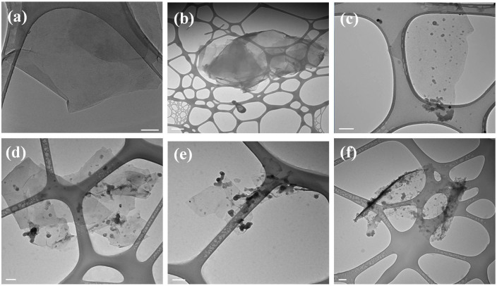
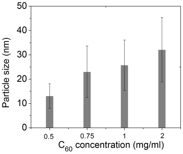
As-prepared rGO and C60/rGO hybrid were characterized by transmission electron microscope (TEM), as shown in Figure 1. The rGO shows a smooth surface and no particles on its surface are observed. The C60-decorated graphene samples prepared using 0.5, 0.75, 1 and 2 mg/ml C60 solution show some dark nanoparticles (NPs), which should be C60 clusters. However, no C60 nanoparticles are observed on the surface of the C60/rGO hybrid fabricated with 0.1 mg/ml C60 solution. This might be due to that the concentration gradient of the C60/m-xylene solution is too small to facilitate the diffusion, and thus no NPs were formed after adding another liquid phase. At higher concentrations, the concentration gradient drives the diffusion significantly and resulted in assembly on the liquid-liquid interface. Smaller C60 nanoparticles are spherical while larger nanoparticles possess variable shapes, which might arise from the agglomeration of small spheres31,32,33,34. Most strikingly, graphene layers without C60 molecules tend to restack due to the interlayer π-π interaction, forming few-layered graphene (Figure 1b). On the other hand, the C60/rGO samples showed single or few layered structures, which might stem from the attached C60 particles, which efficiently prevents the restacking and agglomeration of graphene layers during processing in solution. The particle size distribution of the assembled C60 was investigated based on the measurement of C60 clusters and was shown in Figure 2 and Figure S1 (Supplementary Materials). When a 0.5 mg/ml C60 solution was used, the average particle size is 13 nm. Higher C60 concentrations result in larger particles and reach 23, 26 and 32 nm for 0.75, 1 and 2 mg/ml, respectively. The increased particle size should result from the higher C60 concentration, which tends to form larger seeds for nanoparticle growth. Since changing C60 concentration from 0.75 to 1 mg/ml has little effect on the seed size, no obvious difference on C60 nanoparticle size was observed when the C60 concentration was increased from 0.75 mg/ml to 1 mg/ml. Additionally, C60-decorated rGO, which was fabricated at a higher C60 concentration, shows wider size distribution of C60 in comparison to that fabricated at a lower concentration. In the initial period of C60 nanoparticle seed formation, the C60 solution suffers from concentration depletion immediately after the nucleation at the interface35,36. The anti-solvent diffused gradually into the interlayer, thus a C60 concentration gradient was formed within the interlayer, which may induce a wide seed size distribution. A higher initial C60 concentration tends to have a greater concentration gradient followed with a wider size distribution of the C60 nanoparticles. It has been reported that other factors, such as the drowning-out ratio (anti-solvent/solvent volume ratios), solvent type, and anti-solvent type can influence the morphology of nanoparticles37. This may provide effective approaches to further tune the size of C60 nanoparticles.
Figure 1. TEM images of graphene (a) and C60/graphene hybrid fabricated using 0.1 mg/ml (b), 0.5 mg/ml (c), 0.75 mg/ml (d), 1 mg/ml (e) and 2 mg/ml (f) C60 solution.
(Scale bar: 100 nm).
Figure 2. Size of C60 cluster at C60/rGO hybrids as a function of initial C60 concentration.
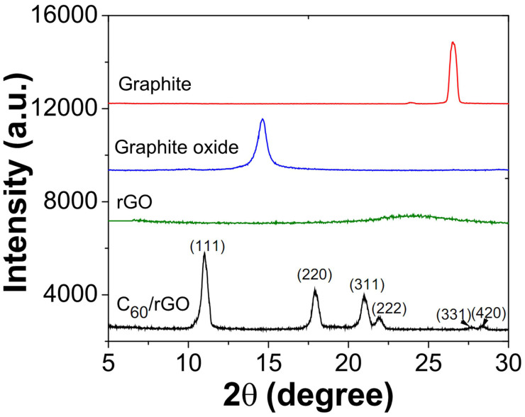
The rGO and C60/rGO samples were characterized by XRD and Raman spectra, as shown in Figure 3 and Figure 4, respectively. In Figure 3, the (002) peak at 27° for pristine graphite indicates an interlayer spacing of 0.34 nm. The (002) peak of graphene oxide (GO) is shifted to 14.6°, indicating that the interlayer spacing increases to 0.72 nm after oxidization38. After chemical reduction by hydrazine, the sharp (002) peak of graphite oxide disappeared while another broad peak of around 24° shows up. The disappearance of the sharp peak can be attributed to the exfoliation of layered structures of graphite oxide. The broad peak may stem from the partial restacking of exfoliated graphene layers. C60/rGO hybrids show characteristic peaks of C60 at 10.8°, 17.7°, 20.8°, 21.7°, 27.5° and 28.2° corresponding to the (111), (220), (311), (222), (331) and (420) diffraction of C60, respectively39. The broad diffraction of graphene in the range of 22° to 26° disappeared and this might be attributed to the assembled C60 clusters, which effectively prevented the restacking of the graphene layers. The X-ray diffraction (XRD) patterns indicate that fullerenes had been successfully incorporated onto the surface of graphene and they worked as spacers to keep the individual graphene sheets from restacking.
Figure 3. XRD patterns of graphite, graphite oxide, reduced graphene oxide and C60/rGO hybrid.
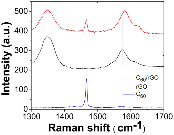
Figure 4. Raman spectra of C60, rGO and C60/rGO hybrid.
Raman spectroscopy is a fast and non-destructive technique to provide insight on the electronic and lattice structures of carbon materials40. Raman spectra of the graphene, pristine C60, and C60/graphene were shown in Figure 4. The rGO shows an intense G-band (sp2 carbon) at 1576 cm−1 which corresponds to the Eg2 phonon at the centre of the Brillouin zone41. The D-band (sp3 carbon) at 1348 cm−1 comes from the out-of-plane breathing mode of the sp2 carbons, which is due to the presence of defects that were introduced in oxidization and reduction procedure42. The sharp peak at 1466 cm−1 indicates the pentagonal pinch mode Ag(2) of C60 molecules43. The C60/rGO hybrid demonstrated three Raman peaks at 1344 cm−1, 1467 cm−1, 1582 cm−1, corresponding to the D band (1344 cm−1), G band (1582 cm−1) of graphene, and the pentagonal pinch mode of C60 molecules (1467 cm−1), respectively. Moreover, the G band for graphene (1575 cm−1) upshifts to 1582 cm−1 in the C60/graphene hybrid, indicating a charge-transfer from the graphene to C6044. Based on the Raman results, it is confirmed that C60 were successfully assembled onto graphene and the charge-transfer occurred between graphene and C60 molecules.
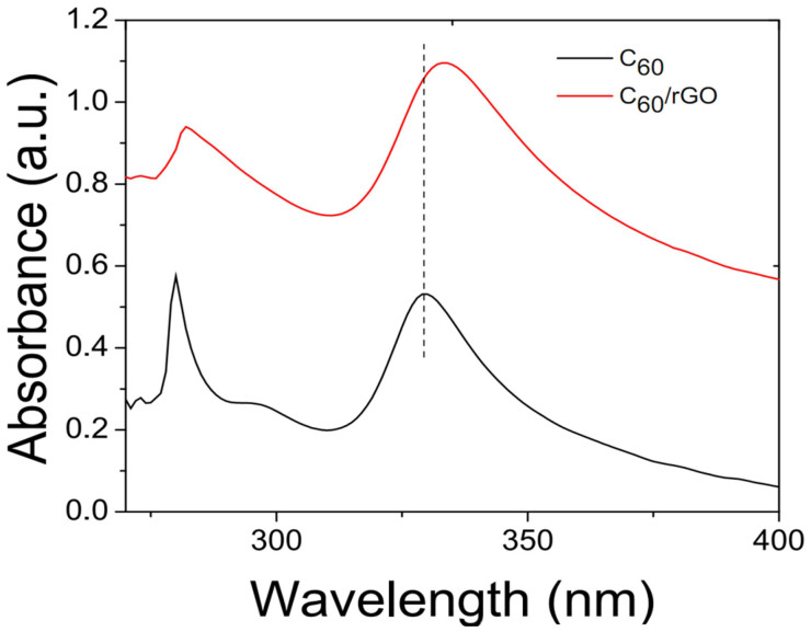
The UV-Vis spectra of C60 and C60/rGO were collected by illuminating C60 and C60/rGO solutions, respectively. As shown in Figure 5, the spectrum of the C60 shows two characteristic peaks at 280 and 328 nm. The peak at 328 nm stems from the π-π electronic transitions45. The red shift of the peak at 328 nm is correlated with the interactions between C60 and other molecules, and thus this peak is a crucial indicator for the interaction of fullerene and aromatic rings46. The π-π stacking of C60 and graphene may delocalize the π electron system and reduce the energy for the electronic transition32. The peak at 328 nm in C60 shifts to 334 nm in the C60/rGO, indicating that C60 was successfully assembled to graphene and the π-π interaction significantly facilitates the formation of the as prepared C60/rGO hybrids.
Figure 5. UV-Vis spectra of C60 and C60/rGO hybrid in solution.
In this work, the Seebeck coefficient, electrical conductivity and thermal conductivity were measured at room temperature. For the loading of rGOxC6030−x nanohybrids in Figure 6, x was the weight fraction of rGO while the C60 fraction was 30 − x in the polymer composites. The Seebeck coefficients and electrical conductivities of C60/rGO-polymer composites were plotted as a function of x, the rGO fraction (See Figure 6). In addition, a three-dimensional plot of Seebeck coefficients of composites was shown Figure 6(a). Moreover, the composite electrical conductivities and Seebeck coefficients were normalized by dividing the pure polymer as shown in Figure 6(c), indicating the improvement factor. The Seebeck coefficients of the rGO and neat PEDOT:PSS film are measured to be 18 μV/K, and 6.4 μV/K, respectively. With the incorporation of C60-decorated rGO, the Seebeck coefficient of rGO/C60-polymer composites are measured to be 24.9, 21.6, 23.8, 22.9, and 21.8 μV/K with rGO loading of 3%, 6%, 15%, 21%, and 27%, respectively. The PEDOT:PSS composite with 30 wt% rGO shows its Seebeck coefficient of 16.2 μV/K, which is close to that of rGO, but 2-fold larger than the neat PEDOT:PSS film. Electrical conductivities of nanohybrids/polymer composites were shown in Figure 6(b). Higher rGO loading in the composites results in higher electrical conductivity. For the loading of rGOxC6030−x nanohybrids, when x = 3%, the electrical conductivity of as-prepared composites is 12190 S/m. Increasing x leads to the increased electrical conductivity, and it reaches to 71503 S/m when x = 30%. By tuning the ratio between C60 and rGO in the polymer composites, the highest power factor (S2σ) of 32.4 μW/m·K2 is achieved x = 21% (C60:rGO = 21%:9% = 7:3) in the as-produced composite, which is more than 10-fold larger than the power factor of neat polymer film (2.8 μW/m·K2).
Figure 6.
(a) Three-dimensional plot of the Seebeck coefficient of composites as a function of C60 and rGO weight loading in composites, indicating more than 4-fold enhancement. (Table S1 shows the Seebeck coefficients with error bars.) (b) The electrical conductivity of nanohybrids-filled polymer composites. (c) Normalized Seebeck coefficient and electrical conductivity to show the improvement factor. α0, σ0 are the Seebeck coefficient and electrical conductivity of pure polymer matrix, respectively.
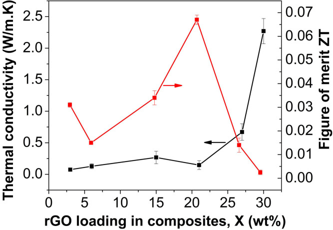
The thermal conductivity and thermoelectric figure of merit were plotted in Figure 7. Increasing x results in higher thermal conductivity. Particularly, the composite thermal conductivity is significantly increased when x > 21%. The composite thermal conductivity is ~0.2 Wm−1K−1 for x = 21%, and it reachs 0.7 Wm−1K−1 at x = 27%, and 2.3 Wm−1K−1 at x = 30%. ZT tended to increase as x ≤ 21%, while it tended to decrease as x > 21%. The highest ZT was achieved at ZT = 0.067 when x = 21% in the rGOxC6030−x nanohybrid-filled polymer composites, where the ratio of C60 to rGO was 3:7.
Figure 7. Thermal conductivity and thermoelectric figure of merit ZT of nanohybrids-filled polymer composites.
Discussion
Graphene is a semi-metallic material with zero-bandgap47,48, but C60-decorated rGO was found to show a finite band gap dependent on the C60 functionalization degree. Incorporating as-produced nanohybrids into the conjugated polymer (PEDOT:PSS) could tune the electronic and phonon transport for tailored thermoelectric properties. Considering the processing challenges and morphology uniformity, the weight loading of C60-decorated rGO was set to 30 wt%. Effects of C60 and rGO loading on the thermoelectric properties of the resultant composites were explored. The electrical conductivity, thermal conductivity and Seebeck coefficient of C60-decorated rGO/polymer composites were all measured at the room temperature.
With the incorporation of C60-decorated rGO, the Seebeck coefficients of rGO/C60-polymer composites show 2-fold larger than the neat PEDOT:PSS film (Figure 6(a)). Addition of rGO in polymer should increase the carrier mobility in composites, resulting in higher electrical conductivity and higher Seebeck coefficient23. With the incorporation of C60/rGO nanohybrids, the Seebeck coefficient of the resultant composites could show as high as 4-fold improvement in comparison with that of neat PEDOT:PSS film. Higher C60 loading resulted in higher Seebeck coefficient, but would decrease the electrical conductivity. Besides the aforementioned reason, another possible reason might be that the incorporation of C60 might push the Fermi level away from the valence band, resulting in an increased Seebeck coefficient25,49. In addition, C60 nanoparticles assembled on graphene surfaces might preferentially allow high-energy carriers to pass while blocking cold-energy carriers and generating an energy filtering effect50,51,52. Hence, it will increase the mean carrier energy in carrier transport with an enhanced Seebeck coefficient50,51. Moreover, since the C60 nanoparticles are zero-dimensional nanostructures, it might be possible to allow quantum confinement during carrier transport, which will further enhance the Seebeck coefficient1.
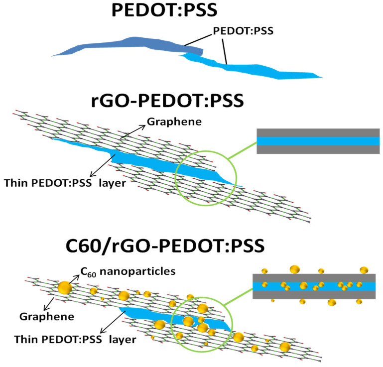
Electrical conductivities of nanohybrids/polymer composites are shown in Figure 6(b). Higher rGO loading in the composites resulted in higher electrical conductivity. Increasing rGO loading x leads to the increased electrical conductivity, and it reaches 71503 S/m when x = 30%. This should be due to the facilitated carrier mobility by the π-π interactions between the graphene surface and PEDOT:PSS24. The lower electrical conductivity at lower rGO loading might be assigned to the incorporation of high-loaded C60 nanoparticles roughing rGO surfaces, leading to the significant electron scattering, disrupting electron transport in polymers. The mechanism was further illustrated in Figure 8. Since the C60/rGO hybrid weight loading in PEDOT:PSS composites was fixed to be 30 wt%, lower rGO weight loading indicated higher C60 weight loading. The strong electron scattering involved by C60 nanoparticles will compromise the increase in electron mobility. Additionally, as aforementioned, the interaction between C60 and rGO was π-π interaction, indicating their intimate contact. The weak contact between hybrid filler and polymer may lead to high electrical contact resistance, resulting in the decrease in electrical conductivity. Moreover, the big difference of electrical conductivity between C60 (~10−19–10−11 S/cm)25 and rGO, or C60 and PEDOT:PSS polymers could further reduce the electrical conductivity. Due to the high electrical resistivity of C60, the composites electrical conductivity was decreased at a higher fraction of C60.
Figure 8. Schematic illustration of carrier transport in the neat polymer film, rGO-polymer and C60/rGO nanohybrids-filled polymer composites.
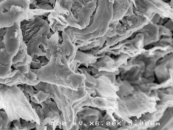
As shown in Figure 7, increasing x resulted in higher thermal conductivity. Particularly, the composite thermal conductivity was significantly increased when x > 21%. The rGO is highly thermal conductive and may form the percolation network in PEDOT:PSS matrix at higher loading. When x > 21%, the ratio of C60 to rGO was less than 1:9, and thus C60 loading fraction is too low to prevent the direct contact between neighbored rGO layers. When x < 21%, the ratio of C60 to rGO was larger than 1:9, and thus high loading of C60 may prevent the direct contact between neighbored rGO, resulting in high thermal interfacial resistance between neighbored rGO layers52. In addition, the percolation network of rGO might be disrupted due to its low fractions. Secondly, high fraction of C60 nanoparticles also contributed low phonon transport path since C60 showed thermal conducting of 0.16 W/m·K. Moreover, nanoscaled C60 decoration on the graphene surface will create a rough interface between filler and matrix, resulting in significant phonon scattering and thus thermal conductivity17. As shown in Figure 2, the C60 particle size on graphene surfaces ranges from ~10 nm to ~40 nm. Large C60 particles scatter phonons with middle wavelengths, small C60 particles scatter phonons with short wavelengths, and thin PEDOT:PSS layers between rGO layers formed interfaces for scattering phonons with long wavelengths. For phonons which carry most of the heat, an average mean-free-path can be plausibly defined. So when the particle size matches the phonon mean free path in PEDOT:PSS, effective phonon scattering will occur according to Casimir regime53,54. The C60 nanoparticles on the surface of graphene facilitate scattering phonons with whole wavelengths, achieving a lower lattice thermal conductivity. Of course, C60-decorated graphene would also introduce porous structure due to its hydrophobic feature, and further reduced the thermal conductivity. Porous PANI composites have been reported to optimize thermoelectric ZT by reducing thermal conductivity without compromising the electrical conductivity18. A SEM image of nanohybrid composites at x = 9% is shown in Figure 9, and micro-scaled pores were observed.
Figure 9. Typical microstructure of nanohybrid-filled polymer composites.
The ZT was also calculated as function of x in the rGOxC6030−x nanohybrid-filled polymer composites, as shown in Figure 8. As x ≤ 21%, ZT tended to increase, since the electrical conductivity rose much faster than the thermal conductivity, as shown in Figure 6 and 8. When x > 21%, ZT tended to decrease since the thermal conductivity of the composites increased drastically, much faster than electric conductivity. As a result, the highest ZT was achieved at ZT = 0.067 when x = 21% in the rGOxC6030−x nanohybrid-filled polymer composites, where the ratio of C60 to rGO was 3:7. For comparison, thermoelectrics of graphene/polymer composites and fullerene/polymer composites were also investigated, respectively, but their ZT was at the level of 10−3. Therefore, the synergistic effects of graphene and C60 can balance the conflicts of the thermal/electric transport and resulted in the largest ZT in the polymer composites.
In conclusion, hierarchical fullerene-graphene nanohybrids were successfully synthesized and the structure characterizations including TEM, XRD, Raman and UV-Vis spectra have confirmed the decoration of fullerene on rGO and charge transfer between them. Subsequently, organic thermoelectric materials were fabricated by integrating such novel hierarchical nanohybrids into a conjugated polymer. In the hierarchical nanohybrid-filled polymer composites, 4-folder improvement in the Seebeck coefficient was achieved as compared to the neat polymer film due to the potential interfacial energy filtering. Tuning the ratio of C60 to graphene in the nanohybrids can make electrical conductivity increment surpassed the increase in the thermal conductivity, resulting in an optimal ZT = 0.067, more than10-fold improvement in comparison to the single-phase filler-based polymer composites. The strategy of integrating nanohybrids consisting of multiple-dimensional heterogeneous nanomaterials into polymers points out a new route towards high-performance organic thermoelectric materials.
Methods
Materials
Graphite was kindly provided by Asbury Carbons. Fullerene (98%, Sigma Aldrich) was used without further purification. The sodium chloride (>99%), N,N-Dimethylformamide (DMF, anhydrous, 99.8%), phenylhydrazine (97%), isopropyl alcohol (IPA, 99.7%), and m-xylene (anhydrous, ≥99%) were purchased from Sigma-Aldrich. The nitric acid (fuming, ACS reagent) was purchased from Acros Organics. PEDOT:PSS was (PH 1000) was purchased from Clevios.
Preparation of graphite oxide
Graphene was fabricated through chemical reduction of exfoliated graphite oxide. Graphite oxide was prepared with a modified Brodie's method55. Typically, graphite (10 g), fuming nitric acid (160 ml), and sodium chlorate (85 g) were mixed at room temperature, but without the subsequent aging used in the Brodie's method. The mixture was stirred for 24 hrs, followed by washing, filtration, and cleaning as described by Brodie. Graphite oxide was collected through a precipitation method and evaporation of the solution.
Preparation of chemically reduced graphene oxide (rGO)
Graphene nanosheets were achieved by reducing graphite oxide with phenylhydrazine. Typically, 200 mg graphite oxide was dispersed in 20 ml DMF by tip sonication at 50 W (Misonix sonicator 3000) for 1 hour, resulting in exfoliated graphene oxide. Then 0.5 ml phenylhydrazine (35 wt%, Sigma-Aldrich) was added. The mixture was stirred at room temperature for 24 hours, followed by washing with DMF (500 ml) and ethanol (500 ml), respectively. The materials were filtrated and annealed in vacuum oven at 270°C overnight, resulting in reduced graphene.
Preparation of C60/rGO nanohybrids
The C60/rGO nanohybrids were assembled by π-π conjugation in the liquid-liquid interface. Typically, C60 and rGO were dispersed in m-xylene and IPA, respectively, through ultra-sonication. Then the rGO/IPA (500 mg/l) solution was injected into the C60/m-xylene solution slowly at a volume ratio of 1:1. The color of the interacted interface of two solutions immediately became dark green, indicating the hybridization of C60 and rGO. Subsequently, the interfacial suspension was extracted and transferred into another beaker every 15 min using a syringe. Five different concentrations (0.1, 0.5, 0.75, 1 and 2 mg/ml) of C60/m-xylene solution were used.
Preparation of C60/rGO-polymer composites
The C60/rGO-polymer composite was prepared by mixing extracted C60/rGO nanohybrids with PEDOT:PSS by gentle stirring, and subsequent drying at 50°C overnight. The weight ratio between hybridized nanohybrids and PEDOT:PSS was 3:7. The ratio of fullerene to rGO in the nanohybrid was 1:9, 3:7, 5:5, 8:2, 9:1, and the samples were named as S1, S2, S3, S4, and S5, respectively.
Characterization
XRD patterns of C60/rGO samples were collected by Powder X-ray diffraction (XRD, Rigaku Ultima III diffractometer, 40 kV, 44 mA, with Cu KR (λ = 1.54 Å)) was used to study the C60/graphene samples, and the measurements were taken at a 2θ range of 5° ≤ 2θ ≤ 40° at room temperature. Powder XRD patterns were analyzed by referring to the International Centre for Diffraction Data (ICDD) powder diffraction file (PDF) database. The UV–Vis spectroscopy was collected with a Perkin Elmer Lambda 1050 spectrometer by placing sample solution in a quartz cuvette. High-resolution transmission electron microscopy (HRTEM, Hitachi H-7650) with an acceleration voltage of 60 kV and scanning electron microscopy (SEM, Hitachi S5000) were employed to characterize the sample morphology. Raman spectra were collected using SENTTERA Raman system model. Electrical conductivity measurements were performed on a SRM probe (Bridge Technology Inc.) by a standard four-point probe method with a Keithley 2400 current source meter and a Keithley 2182A Nanovoltmeter at the room temperature. For the Seebeck coefficient measurements, the thermal voltage was achieved by connecting Keithley 2182A Nanovoltmeter with two identical bare copper wires, which were bonded onto pellets at 20 mm spacing by silver paste. The temperature gradient was obtained using two surface temperature thermocouples (Omega Inc., controlled by SM325 thermometer data logger). The Seebeck coefficient measurement was calibrated before measurement, and the Seebeck coefficient was calculated with S = −ΔV/ΔT + SCu, where SCu is 6.5 uV/K at room temperature56. Thermal conductivity was measured by LFA 447 Nanoflash thermal analysis equipment (NETZSCH Instruments) with an error of ±3%. The samples were cold pressed and cut into 6 mm by 6 mm cubic sheets. Prior to the thermal conductivity measurement, the sample density was derived from the measured volume and weight. The sample thickness ranged from 0.2 mm to 0.6 mm, comparable with the reference material. All thermoelectric properties were measured at the room temperature.
Author Contributions
S.R.W. developed the idea for this work; S.R.W., K.Z. and Y.Z. conceived and designed the experiments; K.Z. and Y.Z. prepared the samples; Y.Z. performed TEM, XRD, and UV-Vis measurements; K.Z. performed Raman characterization and measured the thermoelectric properties; S.R.W., K.Z. and Y.Z. analyzed the results and prepared the manuscript. K.Z. and Y.Z. contributed equally to this work.
Supplementary Material
Supplementary information
Acknowledgments
The authors acknowledge the funding support from National Science Foundation CAREER Award (0953674) and China Scholarship Council (NO.2009663056).
References
- Dresselhaus M. S. et al. New directions for low-dimensional thermoelectric materials. Adv. Mater. 19, 1043–1053 (2007). [Google Scholar]
- Goldsmid H. J. Thermoelectric Refrigeration (Plenum, New York, 1964). [Google Scholar]
- Snyder G. J. & Toberer E. S. Complex thermoelectric materials. Nat. Mater. 7, 105–114 (2008). [DOI] [PubMed] [Google Scholar]
- Medlin D. L. & Snyder G. J. Interfaces in bulk thermoelectric materials: a review for current opinion in colloid and interface science. Curr. Opin. Colloid. Interface Sci. 14(4), 226–235 (2009). [Google Scholar]
- Zebarjadi M., Esfarjani K., Dresselhaus M. S., Ren Z. F. & Chen G. Perspectives on thermoelectrics: from fundamentals to device applications. Energy Environ. Sci. 5(1), 5147–5162 (2012). [Google Scholar]
- Hsu K. F. et al. Cubic AgPb(m)SbTe(2 + m): bulk thermoelectric materials with high figure of merit. Science 303, 818–821 (2004). [DOI] [PubMed] [Google Scholar]
- Hicks L. D. & Dresselhaus M. S. Thermoelectric figure of merit of a one-dimensional conductor. Phys. Rev. B 47, 16631–16634 (1993). [DOI] [PubMed] [Google Scholar]
- Venkatasubramanian R., Siivola E., Colpitts T. & O'Quinn B. Thin-film thermoelectric devices with high room-temperature figures of merit. Nature 413, 597–602 (2001). [DOI] [PubMed] [Google Scholar]
- Poudel B. et al. High-thermoelectric performance of nanostructured bismuth antimony telluride bulk alloys. Science 320, 634–638 (2008). [DOI] [PubMed] [Google Scholar]
- Hochbaum A. I. & Yang P. Semiconductor Nanowires for Energy Conversion. Chem. Rev. 110, 527–546 (2010). [DOI] [PubMed] [Google Scholar]
- Moizhes B. Y. & Nemchinsky V. A. in Proc. for the 11th Int. Conf. on Thermoelectrics, University of Texas, Arlington, TX 1992.
- Humphrey T. E., O'Dwyer M. F. & Linke H. Power optimization in thermionic devices. J. Phys. D: Appl. Phys. 38, 2051–2054 (2004). [Google Scholar]
- Ravich Y. I. CRC Handbook of Thermoelectrics. (CRC Press, New York, 1995). [Google Scholar]
- Cao Y. Q., Zhu T. J. & Zhao X. B. Thermoelectric Bi2Te3 nanotubes synthesized by low-temperature aqueous chemical method. J. Alloys Compd. 449, 109–112 (2008). [Google Scholar]
- Lee J. et al. A novel approach for fabrication of bismuth-silicon dioxide core-shell structures by atomic layer deposition. J. Mater. Chem. 19, 7050–7054 (2009). [Google Scholar]
- Vineis C. J., Shakouri A., Majumdar A. & Kanatzidis M. G. Nanostructured thermoelectrics: big efficiency gains from small features. Adv. Mater. 22, 3970–3980 (2010). [DOI] [PubMed] [Google Scholar]
- Yao Q., Chen L. D., Zhang W. Q., Liufu S. C. & Chen X. H. Enhanced thermoelectric performance of single-walled carbon nanotubes/polyaniline hybrid nanocomposites. ACS Nano 4, 2445–2451 (2010). [DOI] [PubMed] [Google Scholar]
- Zhang K., Davis M., Qiu J. J., Hope-Weeks L. & Wang S. R. Thermoelectric properties of porous multi-walled carbon nanotube/polyaniline core/shell nanocomposites. Nanotechnology 23, 385701 (2012). [DOI] [PubMed] [Google Scholar]
- Yu C. H., Kim Y. S., Kim D. Y. & Grunlan J. C. Thermoelectric behavior of segregated-network polymer nanocomposites. Nano Lett. 8, 4428–4432 (2008). [DOI] [PubMed] [Google Scholar]
- Kim D. Y., Kim Y. S., Choi K. W., Grunlan J. C. & Yu C. H. Improved thermoelectric behavior of nanotube-filled polymer composites with poly(3,4-ethylenedioxythiophene) poly(styrenesulfonate). ACS Nano 4, 513–523 (2010). [DOI] [PubMed] [Google Scholar]
- Xiang J. L. & Drzal L. T. Templated growth of polyaniline on exfoliated graphene nanoplatelets (GNP) and its thermoelectric properties. Polymer 53, 4202–4210 (2012). [Google Scholar]
- Du Y. et al. Simultaneous increase in conductivity and Seebeck coefficient in a polyaniline/graphene nanosheets thermoelectric nanocomposite. Synth. Met. 161, 2688–2692 (2012). [Google Scholar]
- Zhao Y., Tang G. S., Yu Z. Z. & Qi J. S. The effect of graphite oxide on the thermoelectric properties of polyaniline. Carbon 50, 3064–3073 (2012). [Google Scholar]
- Kim G. H., Hwang D. H. & Woo S. I. Thermoelectric properties of nanocomposite thin films prepared with poly(3,4-ethylenedioxythiophene) poly(styrenesulfonate) and graphene. Phys. Chem. Chem. Phys. 14, 3530–3536 (2012). [DOI] [PubMed] [Google Scholar]
- Paloheimo J., Isotalo H., Kastner J. & Kuzmany H. Conduction mechanisms in undoped thin-films of C60 and C60/70. Synth. Met. 56, 3185–3190 (1993). [Google Scholar]
- Sumino M. et al. Thermoelectric properties of n-type C-60 thin films and their application in organic thermovoltaic devices. Appl. Phys. Lett. 99, 093308 (2011). [Google Scholar]
- Cook B. A., Harringa J. L. & Loughin S. Fullerite additions as a phonon scattering mechanism in p-type Si-20 at.% Ge. Mat. Sci. Eng. B-Solid. 41, 280–288 (1996). [Google Scholar]
- Shi X. et al. Influence of fullerene dispersion on high temperature thermoelectric properties of Ba(y)Co(4)Sb(12)-based composites. J. Appl. Phys. 102, 103709 (2007). [Google Scholar]
- Popov M. et al. C60-doping of nanostructured Bi-Sb-Te thermoelectrics. Phys. Status Solidi A. 208, 2783–2789 (2011). [Google Scholar]
- Vavro J., Llaguno M. C., Satishkumar R., Luzzi D. E. & Fischer J. E. Electrical and thermal properties of C60-filled single-wall carbon nanotubes. Appl. Phys. Lett. 80, 1450–1452 (2002). [Google Scholar]
- Zhang Y. et al. Functionalization of graphene sheets through fullerene attachment. J. Mater. Chem. 21, 5386–5391 (2011). [Google Scholar]
- Yang J. et al. Reduced graphene oxide (rGO)-wrapped fullerene (C60) wires. ACS Nano 5, 8365–8371 (2011). [DOI] [PubMed] [Google Scholar]
- Das M. R. et al. Synthesis of silver nanoparticles in an aqueous suspension of graphene oxide sheets and its antimicrobial activity. Colloid. Surface B. 83, 16–22 (2011). [DOI] [PubMed] [Google Scholar]
- Mao A. Q. et al. Synthesis of graphene oxide sheets decorated by silver nanoparticles in organic phase and their catalytic activity. J. Phys. Chem. Solids. 73, 982–986 (2012). [Google Scholar]
- Ji H. X. et al. Controllable preparation of submicrometer single-crystal C-60 rods and tubes trough concentration depletion at the surfaces of seeds. J. Phys. Chem. C 111, 10498–10502 (2007). [Google Scholar]
- Alargova R. G., Deguchi S. & Tsujii K. Stable colloidal dispersions of fullerenes in polar organic solvents. J. Am. Chem. Soc. 123, 10460–10467 (2001). [DOI] [PubMed] [Google Scholar]
- Jeong J., Kim W. S., Park S. I., Yoon T. S. & Chung B. H. Synthesis and characterization of various-shaped C-60 microcrystals using alcohols as antisolvents. J. Phys. Chem. C. 114, 12976–12981 (2010). [Google Scholar]
- Wang S. R., Zhang Y., Abidi N. & Cabrales L. Wettability and surface free energy of graphene films. Langmuir 25, 11078–11081 (2009). [DOI] [PubMed] [Google Scholar]
- Yoshimoto S., Amano J. & Miura K. Synthesis of a fullerene/expanded graphite composite and its lubricating properties. J. Mater. Sci. 45, 1955–1962 (2010). [Google Scholar]
- Ferrari A. C. & Basko D. M. Raman spectroscopy as a versatile tool for studying the properties of graphene. Nat. Nanotech. 8, 235–246 (2013). [DOI] [PubMed] [Google Scholar]
- Soldano C., Mahmood A. & Dujardin E. Production, properties and potential of graphene. Carbon 48, 2127–2150 (2010). [Google Scholar]
- Stankovich S. et al. Synthesis of graphene-based nanosheets via chemical reduction of exfoliated graphite oxide. Carbon 45, 1558–1565 (2007). [Google Scholar]
- Zhang X. Y. et al. Synthesis and characterization of a graphene-C-60 hybrid material. Carbon 47, 334–337 (2009). [Google Scholar]
- Yu D. S., Park K., Durstock M. & Dai L. M. Fullerene-grafted graphene for efficient bulk heterojunction polymer photovoltaic devices. J. Phys. Chem. Lett. 2, 1113–1118 (2011). [DOI] [PubMed] [Google Scholar]
- Domínguez-Chávez J. G. et al. Double Molecular Antenna Pyrene-Bridge-Fullerene C60. The Open Organ. Chem. J. 4, 15–23 (2010). [Google Scholar]
- Chubarova E. V. & Melenevskaya E. Y. Analysis of interactions in fullerene-solvent-polymer system by UV-spectroscopy. Fuller. Nanotub. Car. N. 16, 640–643 (2008). [Google Scholar]
- Pei S. F. & Cheng H. M. The reduction of graphene oxide. Carbon 50, 3210–3228 (2012). [Google Scholar]
- Wassei J. K. & Kaner R. B. Graphene, a promising transparent conductor. Mater. Today 13, 52–59 (2010). [Google Scholar]
- Poehler T. O. & Katz H. E. Prospects for polymer-based thermoelectrics: state of the art and theoretical analysis. Energ. Environ. Sci. 5, 8110–8115 (2012). [Google Scholar]
- Meng C. Z., Liu C. H. & Fan S. S. A promising approach to enhanced thermoelectric properties using carbon nanotube networks. Adv. Mater. 22, 535–539 (2010). [DOI] [PubMed] [Google Scholar]
- Humphrey T. E., O'Dwyer M. F. & Linke H. Power optimization in thermionic devices. J. Phys.: D. Appl. Phys. 38, 2051–2054 (2005). [Google Scholar]
- Yu A. P. et al. Enhanced thermal conductivity in a hybrid graphite nanoplatelet – carbon nanotube filler for epoxy composites. Adv. Mater. 20, 4740–4744 (2008). [Google Scholar]
- Sumirat Y. I. & Shimamura A. S. Theoretical consideration of the effect of porosity on thermal conductivity of porous materials. J. Porous Mater. 13, 439–443 (2006). [Google Scholar]
- Cahill D. G. et al. Nanoscale thermal transport. J. Appl. Phys. 93, 793–818 (2003). [Google Scholar]
- Wang S. R., Tambraparni M., Qiu J. J., Tipton J. & Dean D. Thermal expansion of graphene composites. Macromolecules 42, 5251–5255 (2009). [Google Scholar]
- Burkov A. T., Heinrich A., Konstantinov P. P., Nakama T. & Yagasaki K. Experimental set-up for thermopower and resistivity measurements at 100-1300 K. Meas. Sci. Technol. 12, 264–272 (2001). [Google Scholar]
Associated Data
This section collects any data citations, data availability statements, or supplementary materials included in this article.
Supplementary Materials
Supplementary information


